MultiTech CT300 User Guide
This document provides information for initial setup, preparation, and use of the MultiTech CT300.
Document Part Number: S000832 Rev. 1.0

About the MTCT300
MultiTech CT300 (MTCT300) is a wireless and self-powered electrical current monitoring device. It is capable of reporting average, peak, and minimum RMS Amperes and tracking accumulated Amp-Hours. The device parasitically harvests energy from the monitored conductor, negating the need for routine maintenance to replace or charge batteries.
MTCT300 uses sub-gigahertz LoRaWAN for long range wireless communications. This IoT interface can be deployed as a private network, or used with an available public one. The use of short data messages increases reliability of transmission in suboptimal environments such as metal electrical panels.
Ordering Options
| Ordering Part Number | Description | Region |
|---|---|---|
| MTCT300-NA-1 | Industrial wireless 300A current transformer for energy monitoring – 1 Pk |
Canada United States |
| MTCT300-NA-10 | Industrial wireless 300A current transformer for energy monitoring – 10 Pk | |
| MTCT300-EU-1 | Industrial wireless 300A current transformer for energy monitoring – 1 Pk |
European Union United Kingdom |
| MTCT300-EU-10 | Industrial wireless 300A current transformer for energy monitoring – 10 Pk |
Safety Instructions
This manual and device labels provide important safety warnings. Do not use the device in an unspecified manner. Misuse of the device may impair the user’s protection.
- This device should only be installed and serviced by a licensed electrician.
- Use appropriate personal protective equipment (PPE) rated for the electrical source.
- Risk of electric shock: Do not exceed maximum voltage ratings when installed on uninsulated conductors.
- Risk of fire or explosion: Device is not rated for use in explosive or flammable atmospheres.
- Do not exceed device temperature ratings.
- Do not exceed maximum current ratings for extended periods of time. Damage to the device may occur.
- Device is not rated for use in wet or condensing humidity environments.
- Do not open or disassemble. The device contains no user serviceable components.
National Electrical Code (NEC) requires a Disconnecting Means/Overcurrent Protection to be installed on all electrical systems. It is the customer’s responsibility to meet applicable electrical regulations. MTCT300 is intended to be installed downstream from Disconnecting Means/Overcurrent Protection on monitored circuits.
Specifications
| Category | Description |
|---|---|
| Operational Characteristics | |
| Voltage | 85 to 480 VAC |
| Power Consumption | 0.7 W1 |
| Frequency | 47 to 63 Hz |
| Temperature Range | -25 to 70 °C |
| Humidity | Typical: < 60% RH |
| Max: 80% RH | |
| Pollution Degree | 2 |
| Operational Altitude | 2000m |
| Mechanical Characteristics | |
| Weight | 2.3 oz (65 g) |
| IP Degree of Protection | IP51 (indoors) |
| Window Dimensions (L×W) | 0.6" × 0.6" (16 × 16 mm) |
| Exterior Dimensions (L×W×D) | 3.2" × 1.25"× 0.6" (82 × 32 × 16mm) |
| Mounting | Wire-Hang |
| Communications | |
| Wireless Interface | 800-900 MHz LoRaWAN |
| LoRaWAN Specification | 1.0.2 RevB |
| Frequency Bands | US915/EU868 |
| LoRaWAN Device Class | Class A |
| Transmit Power | +20 dBm |
| Receive Sensitivity | -137 dBm |
| Certifications | |
| UL/CSA | UL 508, CSA C22.2 #14-18 |
| FCC ID | 2APCG-VUHDC1 |
| RoHS | Compliant |
| Warranty | |
| Warranty | One year from date of purchase. Note: Repair
is by the manufacturer only. Opening MTCT300 voids the
warranty.
|
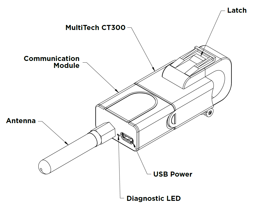
Device Overview
Scoping
Circuit
Determine the circuit(s) where the MTCT300(s) will be installed.
One-Line Electrical Drawing
MultiTech will provide scoping of Current Transformers for our customers. To do this, MultiTech requires one-line electrical drawings and pictures of the conductors. If possible, the pictures need to show the conductor size and insulation type.
Electrical wires are labeled with standardized markings that provide critical information about their construction and intended application. These markings typically include the wire type, voltage rating, wire gauge, and the conductor material. This labeling ensures proper selection, code compliance, and safe installation across a wide range of electrical applications.
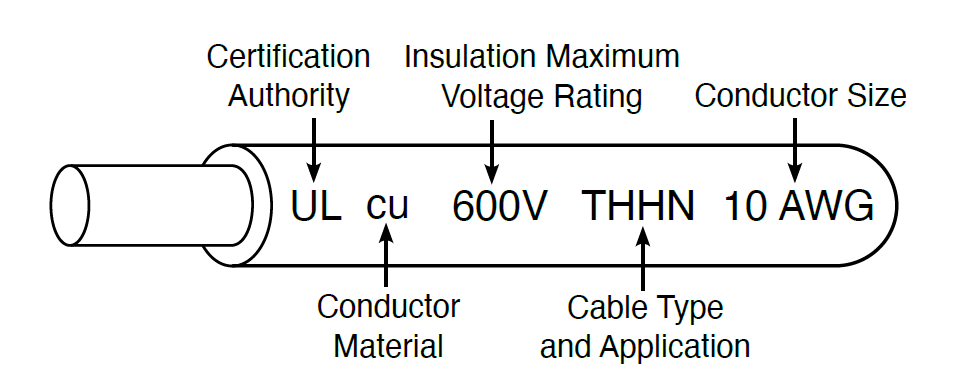 |
Please provide MultiTech with the following information for proper device selection. |
| Conductor Size: ______________ | |
| Insulation Max Voltage Rating: ______________ | |
| Cable Type and Application: ______________ | |
| Conductor Type: ______________ | |
| Certification: ______________ |
The correct Current Transformer for the given conductor(s) can be determined once the conductor size that the Current Transformer will be installed on is determined. The appropriate Current Transformer can be identified once the conductor size is determined. Using the conductor(s) size and the table in Common Conductor Specifications, select the appropriately sized Current Transformer.
Conductor Sizing
The outer diameter of an electrical wire is influenced by several key factors, each directly related to the markings and specifications found on the wire:
- Wire Gauge (AWG or kcmil) – The larger the wire size, the thicker the cable. For example, a 10 AWG wire has a significantly smaller conductor cross-section than a 4/0 wire or 500 kcmil cable. As the conductor size increases, more material is needed, which directly increases the outer diameter.
- Conductor Material (Copper vs. Aluminum) – Aluminum has lower conductivity than copper, so a larger diameter conductor is required to carry the same current. This means aluminum conductors generally result in cables with larger outer diameters than their copper counterparts at the same current rating.
- Insulation Type (e.g., THHN, XHHW, RHW) – Different insulation materials have different thickness requirements and thermal properties. For instance, XHHW insulation is typically thicker than THHN, resulting in a larger outer diameter even for the same gauge and conductor material.
- Voltage Rating – Higher voltage ratings often require thicker insulation layers to maintain dielectric strength and prevent breakdown. A 1,000V-rated cable will generally have a larger outer diameter than a 600V-rated cable of the same gauge and type.
- Wire Construction (Solid vs. Stranded) – Stranded conductors consist of many small wires twisted together and require more space and insulation than a solid conductor. This adds to the cable’s overall diameter, especially in flexible or high-strand-count designs.
In situations where a conductor’s type, gauge and other ratings cannot be directly determined. It may be nessesary to measure the outer diameter using a non-conductive tool or upsize the MTCT300 to ensure proper fit.
Common Conductor Specifications
The following chart is based off of 600V THHN/THWN PVC insulation with a Nylon outer jacket per UL standard 83. These values are minimums permitted and may not be characteristic of all cable manufacturers. Nylon jacketing is assumed to be 0.005" (5 mils) and included in the insulation thickness.
Ampacity ratings are per the 2023 NEC Table 310.16 with an ambient temperature of 30°C.
| Wire Size AWG/kcmil | Outer Diameter | 75 °C Ampacity | ||
|---|---|---|---|---|
| Copper | Aluminum | Copper | Aluminum | |
| 14 | 0.111" (2.82mm) | – | 15A | – |
| 12 | 0.130" (3.30mm) | – | 20A | – |
| 10 | 0.164" (4.17mm) | – | 30A | – |
| 8 | 0.185" (4.70mm) | 0.200" (5.08mm) | 50A | 40A |
| 6 | 0.210" (5.33mm) | 0.232" (5.89mm) | 65A | 50A |
| 4 | 0.255" (6.48mm) | 0.275" (6.99mm) | 85A | 65A |
| 2 | 0.305" (7.75mm) | 0.335" (8.51mm) | 115A | 90A |
| 1 | 0.340" (8.64mm) | 0.370" (9.40mm) | 130A | 100A |
| 1/0 | 0.380" (9.65mm) | 0.420" (10.67mm) | 150A | 120A |
| 2/0 | 0.420" (10.67mm) | 0.465" (11.81mm) | 175A | 135A |
| 3/0 | 0.470" (11.94mm) | 0.515" (13.08mm) | 200A | 155A |
| 4/0 | 0.525" (13.34mm) | 0.575" (14.61mm) | 230A | 180A |
| 250 | 0.590" (14.99mm) | 0.640" (16.26mm) | 255A | 205A |
| 350 | 0.655" (16.64mm) | 0.715" (18.16mm) | 310A | 250A |
| 500 | 0.745" (18.92mm) | 0.820" (20.83mm) | 380A | 310A |
| 600 | 0.805" (20.45mm) | 0.885" (22.48mm) | 420A | 340A |
| 750 | 0.895" (22.73mm) | 0.975" (24.77mm) | 475A | 385A |
| 1000 | 1.030" (26.16mm) | 1.110" (28.19mm) | 545A | 445A |
MTCT300 Specific
| UL Rated | Window |
|---|---|
| 300A Current Transformer | 15.7 mm |
Applicable Circuit Types
Determine the circuit type to identify how many devices are needed. Install one MTCT300 per phase; the neutral typically does not carry full load current in multiphase systems and should not be monitored. See Wiring Color Codes for additional details into identifying a circuit’s type.
For high-current systems with multiple conductors per phase, a single MTCT300 must encompass all conductors in a phase to accurately monitor the current.
| Single-phase two-wire with neutral | 1 MTCT300 Device |
| Single-phase (split-phase) three-wire | 2 MTCT300 Devices |
| Three-phase three-wire (Delta) | 3 MTCT300 Devices |
| Three-phase four-wire (Wye) | 3 MTCT300 Devices |
Load Suitability
MTCT300 is a self-powered device that parasitically harvests energy from the monitored circuit to operate. This gives the MTCT300 the advantage of requiring no external power supply or regular battery changes. However, harvesting from the source imposes a few requirements on the monitored circuit.
- The MTCT300 requires current to be flowing in the monitored circuit in order to harvest energy.
- There is an initial charging time before the MTCT300 has enough energy to begin operation.
- The amount of current flow in the monitored circuit determines how long the MTCT300 needs to charge before operation and what operational state it can maintain.
The MTCT300 has multiple low-power modes to enable circuit monitoring before high-power systems such as the LoRaWAN radio are enabled. These extend the operational range of the device across situations such as low circuit currents or momentary shutoff.
MTCT300 is not suitable for all loads and circuits. The device will perform poorly under the following conditions:
- Loads with less than 1% of the rated sensor current.
- Very low currents impact the accuracy of the current transformer, and may not provide sufficient power harvesting for the MTCT300 to operate reliably.
- Loads that are active for short periods of time.
- Due to the initial charging time, the MTCT300 may not reach operational state before the load shuts off.
- Periodic loads where high-accuracy amp-hour totalization is required.
- Current flowing in the circuit while the MTCT300 is initially charging is not recorded. Loads with many on/off cycles may not give high-accuracy amp-hour totalization.
- MTCT300 continues operating for some time after the load has shut off. Periodic loads where the off-time is shorter than the MTCT300’s power-off discharge will not be impacted by repeated initial charge states.
Non-ideal conditions can be mitigated by externally powering the MTCT300 with a 5V micro USB power supply.
Before Installation
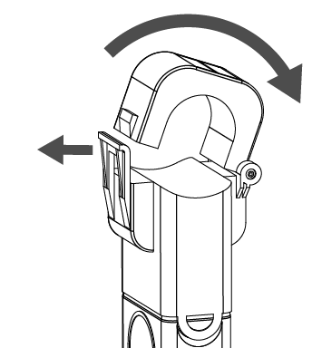
MTCT300 Latch
|
The MTCT300 uses a split-core current transformer to allow easy installation on existing wiring.
Exercise caution when handling devices exposed longterm to heat and high humidity. These conditions can eventually cause the nylon plastic to become brittle, increasing the risk of latch or hinge breakage if forced. |
 |
Installation Location
- Note the MTCT300 can only monitor a single AC phase. Combining phases within a current transformer will result in inaccurate readings due to phase offset.
- Failing to encompass all conductors in a phase will result in inaccurate readings.
- Generally the neutral conductor does not carry full load current in multiphase systems and should not be monitored.
The MTCT300 is designed to hang from the monitored conductors. If installation on a vertical conductor is necessary, non-conductive cable ties or similar are recommended to hold the MTCT300 in place.
For maximum wireless reception the LoRaWAN antenna should be angled away from metal sidewalls as much as possible while not being perpendicular to the antennas on the LoRaWAN gateway.
It is recommended that a minimum of 1" (25mm) of clearance is maintained between current transformer devices such as the MTCT300. Placing multiple current transformers adjacent to each other will impact their accuracy.
Installation
Getting Started
The following tools are recommended:
- Proper PPE required
- Standard hand tools necessary to remove the electrical panel cover
- Multi-Tip Screwdriver
Step 1: Onboard the MTCT300
Use the QR codes on the device bag label to onboard the device.

To onboard the device to MultiTech Cloud, complete the following:
- Scan the Scan to onboard QR code located on the label of the device bag.
- On your smartphone, select the cloud.multitech.com link.
- Log in to your MultiTech Cloud account.Note: If you do not have an account, you must create one first.
- After you log in successfully, the system onboards your device to Device Manager.
To retrieve device credentials, scan the Scan for IDs QR code. The Scan for IDs QR code provides the DevEUI:AppKey used to register the device to an LNS. The JoinEUI for the MTCT300 is 00800000A0000767.
For more instructions on onboarding the device to other LNS providers:
Step 2: Identify the Cable
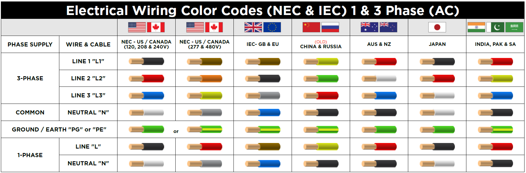
Identify the conductor to install the MTCT300 on. Cables are grouped by Phases: L1, L2, L3. The table below shows the phase color codes for different countries and voltages. It is the installer’s responsibility to confirm the correct phases.
Wiring Color Codes
Step 3: Test the Cable
Test the conductor with a clamp-on ammeter to determine what current is flowing through the conductor. This will allow the installer to know what value should be seen on a visualization application. If the amperage limit is below the minimum amperage for normal operation this indicates that the Current Transformer is in low power mode and will likely not communicate on a regular basis without USB power.
Step 4: Pre-charge the MTCT300
It is recommended to pre-charge the MTCT300 before installing in a panel. Pre-charging the MTCT300 allows data to be sent to the customer system to verify that the MTCT300 works correctly. Pre-charging along with reading the amperage in the conductor with a clamp-on ammeter allows the customer to know that everything is working correctly. Pre-charging can be done using a USB-mini cable plugged into the MTCT300 communication module USB-mini port.
- Plug a USB wall charger into an outlet.
- Plug the USB cable into the USB wall charger.
- Plug the cable into the USB-mini port on the MTCT300.
- The MTCT300 will join the customer LoRaWAN Network Server (LNS) within one minute of plugging the USB charger into the USB port on the communication module. Charge the MTCT300 for at least three minutes before removing the USB cable if you want to have the MTCT300 device operate off of the capacitors.
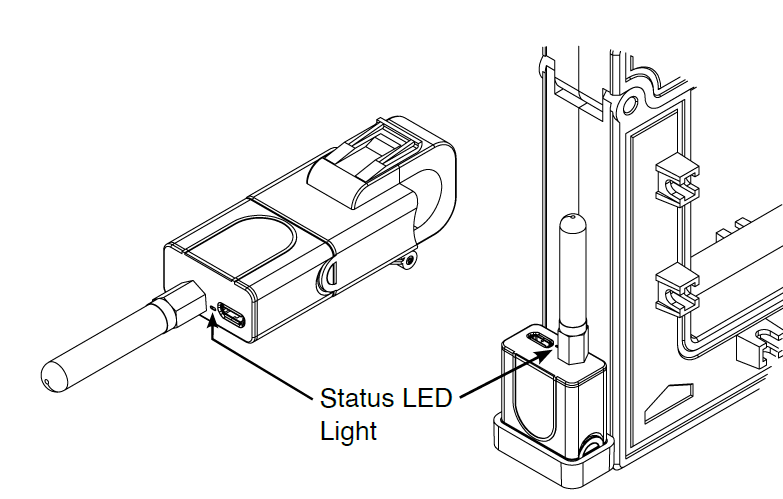
- Observe the LED on the top of the MTCT300 communication module. Once the MTCT300 is powered, the RED LED will begin blinking a series of 20 blinks as the communication module boots up. After the boot-up, the device will attempt to Join the LoRaWAN Network Server (LNS). While trying to join the LNS, the LED will have (3) RED blinks. When the MTCT300 joins the LNS, the communication module LED will blink 2 RED Blinks. This is the normal operation state for the MTCT300. LoRaWAN packets with minute-by-minute circuit data will start flowing. Once joined to the LNS and data flow is confirmed, the installation has been completed successfully.
Step 5: Verify the Data
Using a visualization tool, view the data for the MTCT300 to make sure that correct data is transmitted.
LoRaWAN Data Format
Introduction
LoRaWAN (Long Range Wide Area Network) is a low-power, wide-area networking protocol designed for wireless communication between devices and centralized gateways. It operates on unlicensed radio frequencies (typically in the 868 MHz or 915 MHz ISM bands, depending on region) and is optimized for long-range, low-bandwidth applications such as remote sensing, monitoring, and control.
LoRaWAN is built on top of LoRa® modulation, which enables robust and energy-efficient data transmission over long range or under challenging radio environments such as electrical panels. The protocol defines secure communication, adaptive data rate (ADR), and network scalability, supporting a high device count per gateway.
LoRaWAN networks are typically structured such that devices communicate directly with one or more gateways. These gateways forward data to a LoRaWAN network server (LNS), which handles message deduplication, device authentication, and routing to customer applications.
Data Length Restrictions
LoRaWAN adaptive data rate (ADR) and variable modulation spreading enables tradeoffs between range/noise immunity and data throughput. Devices with good signal strength to the gateway will use efficient data rates and spreading factors to reduce the amount of airtime required to send data. Devices with poor signal will use settings that improve reception at the cost of longer airtime and lower throughput.
LoRaWANregional specifications limit maximum airtime for devices. This ensures fair access for all systems in highly contested radio frequencies. Because the MTCT300 reports data at a high rate compared to typical LoRaWAN devices, it is required that the data packets have limited size to keep the airtime under the regulatory limits in worst-case conditions.
Note that public LoRaWAN networks may throttle devices that violate their terms of use and often impose additional restrictions on airtime and uplink count.
MTCT300 Open-Source Codec
Verified open-source JavaScript codecs (data decoders) are available for a variety of major LoRaWAN network servers (LNS). When deploying the MTCT300 it is highly recommended that these be utilized over developing custom implementations when possible.
The codec’s are freely available here: https://www.multitech.net/developer/software/sensors/.
MTCT300 LoRaWAN Port Field
LoRaWANframes contain a "FPort" field which accompanies data payloads. An FPort value of 0, which is reserved by specification, indicates that the payload contains a LoRaWAN protocol control command. FPort values 1 to 223 are application specific and may be defined by users.
MTCT300 sends and receives user-facing data on FPort 3. Data received on other ports will be discarded.
Uplink Packet Definitions
Uplinks are data packets sent from devices to the LoRaWAN network server (LNS). The MTCT300 defines only a single uplink that contains all of the metrics it reports.
The interval between sent uplinks can be configured. See Transmit Interval for details on building the configuration LoRaWAN downlink.
Packet 50 - Comprehensive
| Byte Index | Field | Type | Description |
|---|---|---|---|
| 0 | Packet ID | uint8 | This value is equal to 50. |
| 1-4 | Amp-Hour Accumulation | uint32 | An unsigned integer in network byte order (MSB) reported in deci-ampere-hours (dAh). |
| 5-6 | Average Current | uint16 | An unsigned integer in network byte order (MSB) reported in deci-amperes (dA). This value is the rolling average of the RMS current since the last transmission. |
| 7 | Max Offset | uint8 | An unsigned integer representing the percent offset above the Average amps value. The peak
amperage can be calculated by the following equation: |
| 8 | Min Offset | uint8 | An unsigned integer representing the percent offset below the Average amps value. The minimum
amperage can be calculated by the following equation: |
| 9 | Capacitor Voltage Scalar | uint8 | An unsigned integer representing the capacitor voltage. The capacitor voltage can be
calculated by the following equation: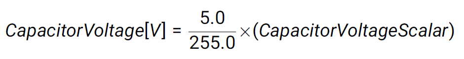 |
| 10 | Temperature Scalar2 | uint8 | An unsigned integer representing the device internal temperature. The temperature in degrees
Celcius can be calculated by the following equation: |
Example Packet 50 - Comprehensive
| Base64 Encoding | MgAAW74DQCEsrog= | ||
| Raw Packet (Hexadecimal Bytes) | [32, 00, 00, 5B, BE, 03, 40, 21, 2C, AE, 88] | ||
| Decoded Values | |||
| Amp-Hours | 2348.6 Ah | Average Current | 83.2A |
| Maximum Current | 110.66A | Minimum Current | 46.59A |
| Capacitor Voltage | 3.41V | Temperature | 24°C |
Downlink Configuration Definitions
Downlinks are data packets sent from the LoRaWAN network server (LNS) to the device. The MTCT300 is configurable via several downlinks described in this section. The following downlinks must be padded to a length of 10 bytes, and values are encoded as IEEE-754 32-bit floating- point (i.e. "float") with network-byte order (MSB). Due to the complexity of this format, it is recommended to use the provided options to prevent invalid or unexpected device operation. Downlinks should be sent to FPort 3.
Device Reboot (Soft Reset)
This will initiate a software reset, causing the device to rejoin the LoRaWAN network.
| Raw Packet (Hexadecimal Bytes) | Base64 Encoding |
|---|---|
| [5A, 00, 00, 00, 00, 00, 00, 00, 00, 00] | WgAAAAAAAAAAAA== |
Factory Reset
This will initiate a factory reset. Accumulated amp-hours and configuration will be set to initial values and the device will reboot.
| Raw Packet (Hexadecimal Bytes) | Base64 Encoding |
|---|---|
| [46, 00, 00, 00, 00, 00, 00, 00, 00, 00] | RgAAAAAAAAAAAA== |
Transmit Interval
The interval between data packets can be configured to reduce the frequency of updates.
Reducing the interval increases power requirements and the minimum circuit current necessary to maintain full power state on the MTCT300. Increasing the transmit interval results in a longer rolling window for averaged current values.
| Transmit Interval | Raw Packet (Hexadecimal Bytes) | Base64 Encoding |
|---|---|---|
| 1 minute (Default) | [54, 00, 00, 00, 70, 42, 00, 00, 00, 00] | VAAAAHBCAAAAAA== |
| 2 minutes | [54, 00, 00, 00, F0, 42, 00, 00, 00, 00] | VAAAAPBCAAAAAA== |
| 5 minutes | [54, 00, 00, 00, 96, 43, 00, 00, 00, 00] | VAAAAJZDAAAAAA== |
| 15 minutes | [54, 00, 00, 00, 61, 44, 00, 00, 00, 00] | VAAAAGFEAAAAAA== |
| 30 minutes | [54, 00, 00, 00, E1, 44, 00, 00, 00, 00] | VAAAAOFEAAAAAA== |
Measurement Interval
The MTCT300 spends the majority of its time harvesting power and transitions to high-resolution measurement on a periodic interval.
Higher resolution data can be achieved by reducing the measurement interval at the cost of greater power requirements and an increased minimum circuit current to maintain full power state on the MTCT300.
It is highly recommended to leave this value at the default configuration.
| Interval (msec) | Raw Packet (Hexadecimal Bytes) | Base64 Encoding |
|---|---|---|
| 200 | [4D, 00, 00, 00, 48, 43, 00, 00, 00, 00] | TQAAAEhDAAAAAA== |
| 500 | [4D, 00, 00, 00, FA, 43, 00, 00, 00, 00] | TQAAAPpDAAAAAA== |
| 1000 (Default) | [4D, 00, 00, 00, 7A, 44, 00, 00, 00, 00] | TQAAAHpEAAAAAA== |
| 2000 | [4D, 00, 00, 00, FA, 44, 00, 00, 00, 00] | TQAAAPpEAAAAAA== |
| 10000 | [4D, 00, 00, 40, 1C, 46, 00, 00, 00, 00] | TQAAQBxGAAAAAA== |
Low Power Threshold
The low power threshold determines when a MTCT300 transitions to increased measurement and transmit intervals to conserve power. This extends the operating region of the device.
Decreasing the low power threshold causes the device to remain in full operation longer, but will result in a rapid shutoff once circuit current falls below the minimum required to sustain full operation.
It is highly recommended to leave this value at the default configuration.
| Threshold (Volt) | Raw Packet (Hexadecimal Bytes) | Base64 Encoding |
|---|---|---|
| 3.9 | [50, 00, 9A, 99, 79, 40, 00, 00, 00, 00] | UACamXlAAAAAAA== |
| 3.4 (Default) | [50, 00, 9A, 99, 59, 40, 00, 00, 00, 00] | UACamVlAAAAAAA== |
| 2.1 | [50, 00, 66, 66, 06, 40, 00, 00, 00, 00] | UABmZgZAAAAAAA== |
Troubleshooting
Status Flashing Codes
| The MTCT300 contains a red LED light. Status is communicated via patterns of flashes described by the following table. |
 |
| Flash Pattern | Condition | Device State |
|---|---|---|
| 1 Flash every 10 seconds (or no light) | MTCT300 is in measurement-only mode or unpowered |
The capacitor voltage is low and the device may soon cease operation. Check that the module is seated securely in its socket on the current transformer and that sufficient current is flowing in the monitored circuit. Depending on the current flow, low-power operation may be expected for some time after initial power-on. |
| 1 Flash every 5 seconds | Low power operation | The device is functioning properly but the capacitor voltage has dropped below the full operation point. The rates of transmission and measurement have been decreased to conserve power. |
| 2 Flashes every 5 seconds | Normal Operation | The device is functioning properly and is joined to a LoRaWAN network. |
| 3 Flashes every 5 seconds | LoRaWAN joining in progress | The device is functioning properly and attempting to join a LoRaWAN network. |
| 20 Flashes at 1Hz | MTCT300 initialization |
The device is initializing after reset. Expected at power-on, occurrences during operation indicate reset due to error conditions. |
Additional Troubleshooting Information
- Using a visualization tool, ensure that the Signal-to-Noise Ratio (SNR) is a positive value, and that Received Signal Strength Indicator (RSSI) is greater than -115.
- For cellular backhaul, make sure that the signal is strong enough. Note that bars on a phone do not always give a true indicator of the cell signal.
- Make sure that there is enough current flowing in the conductor. Using a visualization tool, check to make sure that the supply voltage (capacitor voltage) is above 3.4V. The chart below shows the MTCT300 capacitor voltage (supply voltage) power levels for full operation, low power transmit, measurement only, and non-operational.
Power Harvesting Charge and Discharge
Typical Charge and Discharge
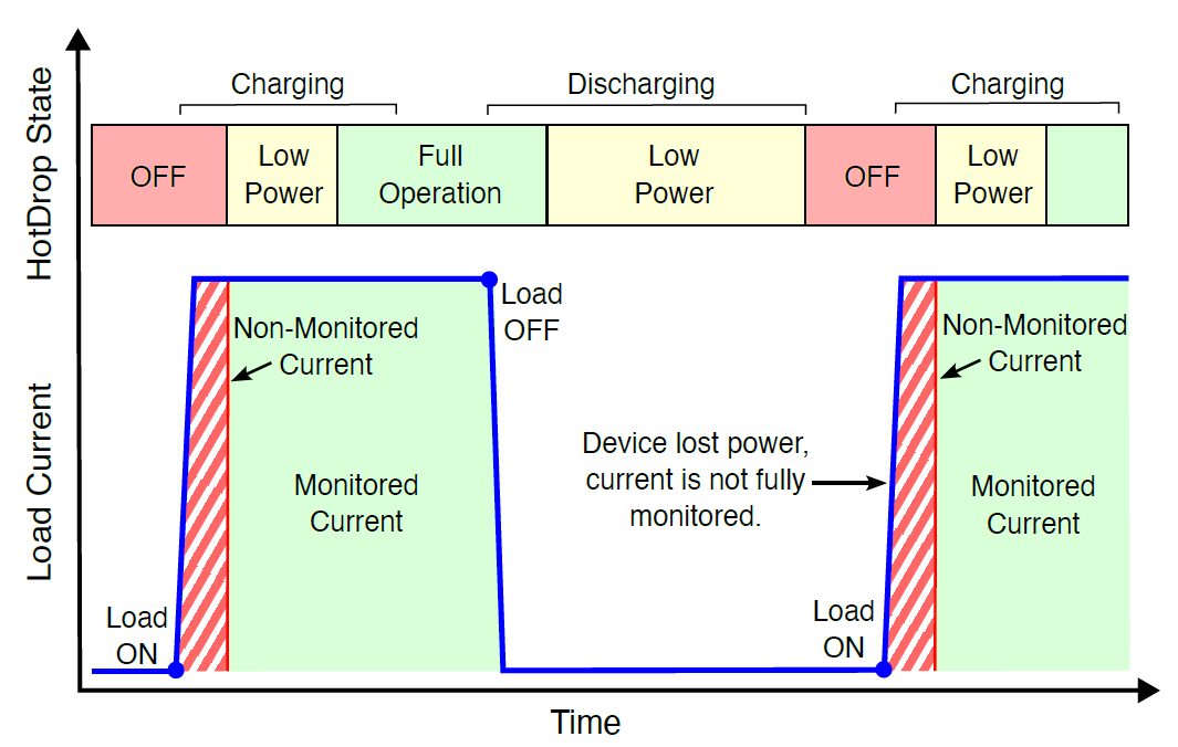
The MTCT300 begins charging its internal capacitor-based energy storage whenever current flows through the monitored circuit. Because the device’s processor, radio, and measurement circuitry require a minimum operating voltage, there is a brief period after energization during which the capacitor has not yet charged sufficiently for the device to function. During this time, the MTCT300 does not collect measurements or record current in its amp-hour totalization.
The length of this initial charge period depends directly on the amount of current in the circuit. Higher currents allow the capacitor to charge more quickly. For detailed behavior by model, refer to Appendix A: Charge Time and Current.
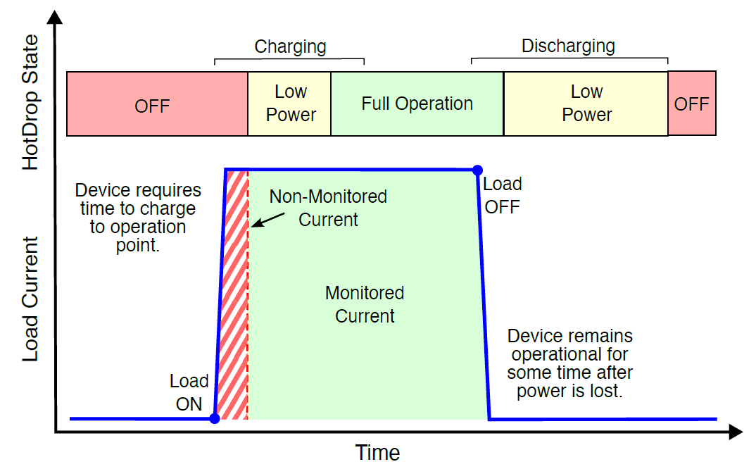
Short Load Interruptions
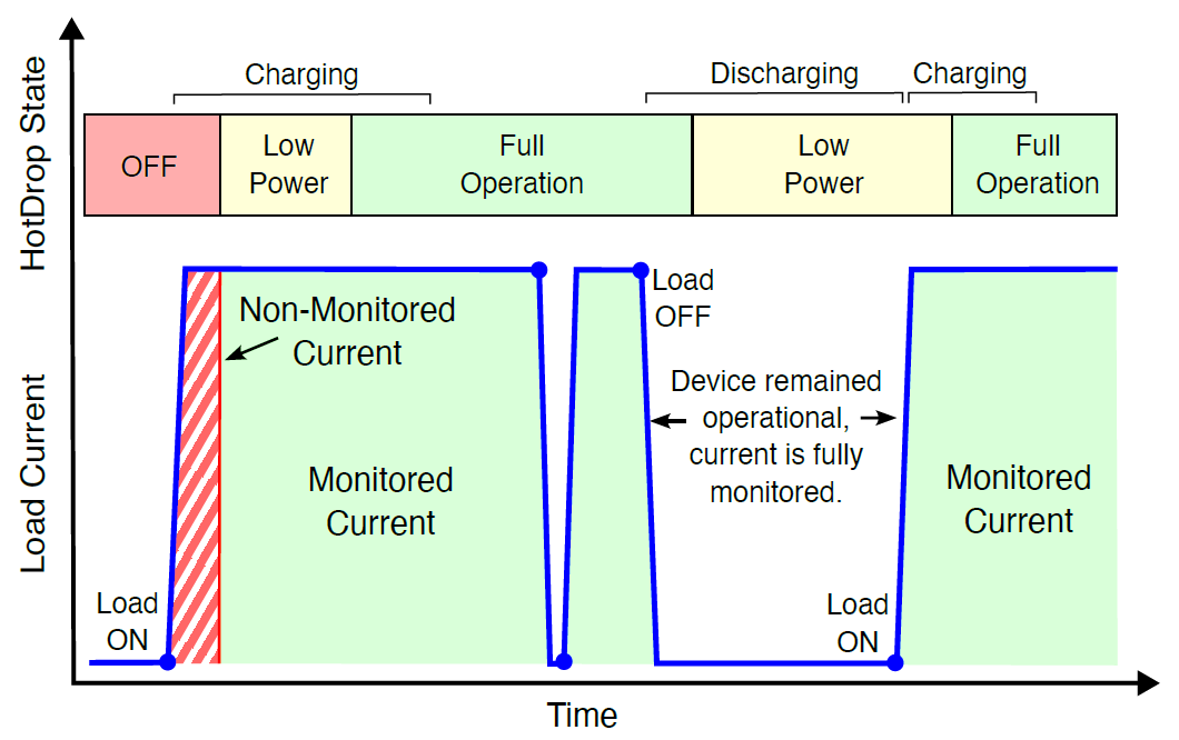
If circuit current is lost, the MTCT300 continues operating from the energy stored in its capacitor. As this energy is depleted, the device transitions through low-power modes to preserve operation. The amount of time a MTCT300 can function during an outage depends on how much excess energy it stored prior to the loss of current. In many cases, short outages will not affect the device’s ability to operate or measure current.
If the outage is brief and the capacitor does not fully discharge, the MTCT300 resumes normal operation without delay once current returns; there is no reinitialization or unmonitored period.
See Appendix B: Discharge Time for information on the holdover time of the MTCT300.
Long Load Interruptions
The MTCT300 will shut down completely if an outage is long enough that the capacitor becomes fully discharged. When current is restored, the device must undergo the initial charge period again before it can resume normal operation. During this time, circuit current is not monitored until the capacitor reaches the minimum operating threshold.
If the MTCT300 is used to monitor periodic loads where extended outages are common, it is recommended to supply external power via a 5V micro USB connection. This is only necessary when accurate amp-hour totalization is required, as it ensures continuous uninterrupted operation.
See Appendix B: Discharge Time for information on the holdover time of the MTCT300.
Capacitor Voltage Power States
The rate at which the internal capacitor is charged and discharged depends on the current flowing through the monitored circuit and the configuration of the MTCT300. In order to prevent the device from unexpectedly losing power while operating (causing data loss), the MTCT300 uses tiered power modes to regulate consumption of high power systems. These power modes and thresholds are described in the following:
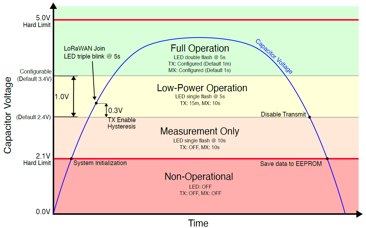
| Event | Description |
|---|---|
| System Initialization | The MTCT300 measurement circuitry requires a minimum of 2.1V to operate. Once the capacitor has charged to this value, the device initializes and begins measurement (MX), but does not currently have enough energy to operate the LoRaWAN radio. |
| Transmit(TX) Enable | The capacitors contain enough energy to power the radio circuits without immediately draining the supply. The device will begin the LoRaWAN joining process and transmit data at a reduced rate to conserve energy. |
| Full Operation | Enough energy is stored that the device can transmit and measure at full speed. The rates of transmit and measurement are configurable by LoRaWAN downlink. |
| Low Power Operation | The device is not harvesting enough energy to maintain full operation. To prevent the device from unexpectedly losing power due to high consumption, the rate of transmit and measurements are reduced. This extends the operational limits of the MTCT300. |
| Transmit Disable | There is no longer sufficient energy to operate the radio without interfering with the measurement circuitry. The MTCT300 will continue to monitor and record data, but will no longer transmit updates until increased power is available. |
| System Shutdown | Below the 2.1V limit, proper operation of the measurement circuitry is no longer guaranteed and the device shuts down. When crossing this limit the device saves measurement values to an EEPROM storage device to prevent data loss. |
Externally Powered Behavior
The MTCT300 can be powered by connecting a 5 Volt supply to its micro USB port. When external power is applied, the device’s internal capacitors charge rapidly regardless of whether current is flowing through the monitored circuit. This feature is useful for pre-charging the device during installation or for maintaining data reporting in the absence of load current.
During startup, the MTCT300 checks for the presence of external power. If detected, it immediately enters full operation, even if the capacitors are not yet fully charged. This check occurs only at power-on. If external power is applied to an already operational MTCT300 it will continue to transition through power states based on the capacitor charge level.
If external power is removed before the capacitors have reached sufficient charge, the device may shut off abruptly. To ensure uninterrupted operation after disconnecting external power, it is recommended that the connection be maintained for at least 30-60 seconds to allow the capacitors to charge.
Common Issues and Resolutions
| Issue | Cause | Resolution |
|---|---|---|
| MTCT300 Not Operating | Insufficient circuit current or initial charging period | The MTCT300 does not have sufficient power to operate. This may be a temporary state while the capacitor initially charges, or there may be insufficient circuit current to maintain a charged state. Check circuit current and proper CT closure. |
| Inaccurate Low-Scale Readings | Metered value below 1% of sensor rating | Sensor accuracy decreases in the extreme low-end range. Use an appropriately sized device for the system. |
| Inaccurate Amp-Hour Totalization | Periodic loads with long inactive time | Each time the MTCT300 restarts due to insufficient current, there is an unmonitored initial charging period. These can aggregate into large offsets for loads that cycle routinely. Consider externally powering the MTCT300 over USB. |
| No Data Reported (Three Status Light Flashes) | Device not joined to a LoRaWAN network | Check the device onboarding to the LoRaWAN network server. Ensure that the antenna is screwed on completely. Reposition the MTCT300 antenna and/or gateway to increase signal strength. |
| No Data Reported (Two Status Light Flashes) | LoRaWAN communication unreliable | The device has joined the LoRaWAN network but there is insufficient signal strength for reliable communication,or significant interference from other wireless or electrical systems. Reposition the MTCT300 antenna and/or gateway to increase signal strength. |
| No Data Reported (One Status Light Flash @ 5s) | Device in low-power transmit mode | The device has insufficient power to maintain full rate transmit. Data will be sent once every 15 minutes. Check circuit current and proper CT closure. |
| No Data Reported (One Status Light Flash @ 10s) | Device in low-power measurement-only mode | The device has insufficient power to transmit and is measuring and recording data only. Check circuit current and proper CT closure. |
| MTCT300 Resets Periodically | Failing LoRaWAN link check (i.e. LinkCheckReq & LinkCheckAns) | The device cannot reliably communicate with the LoRaWAN gateway and is failing consecutive connection checks. This causes a two-hour reset interval. Reposition the MTCT300 antenna and/or gateway to increase signal strength. |
Appendix A: Charge Time and Current
MTCT300 Time to Charge
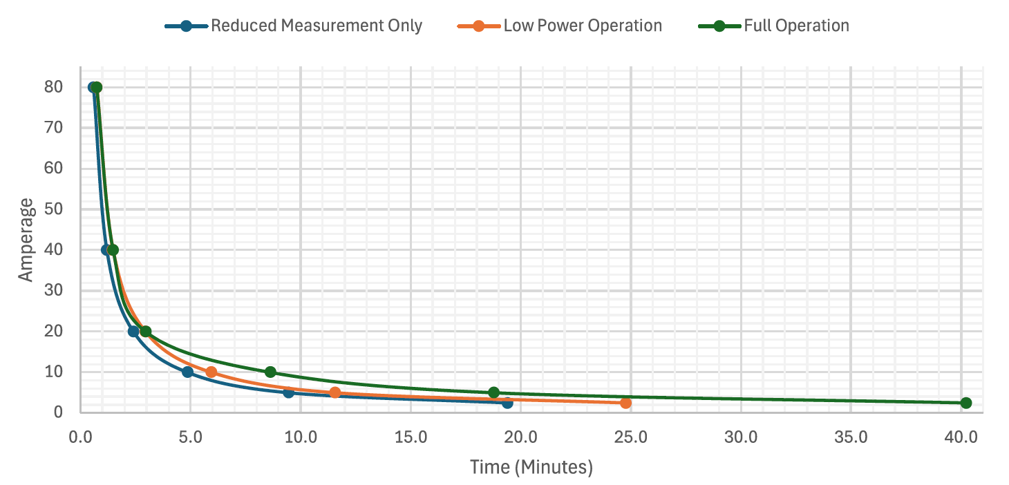
Time to Operation (Minutes)
| Amperage | Measurement Only | Low Power Operation | Full Operation |
|---|---|---|---|
| 80A | 0.6 | 0.7 | 0.7 |
| 40A | 1.2 | 1.5 | 1.5 |
| 20A | 2.4 | 2.9 | 3.0 |
| 10A | 4.9 | 5.9 | 8.6 |
| 5A | 9.5 | 11.6 | 18.8 |
| 2.5A | 19.4 | 24.8 | 40.2 |
Electric Charge to Operation (Amp-Hours)
| Amperage | Measurement Only | Low Power Operation | Full Operation |
|---|---|---|---|
| 80A | 0.8 | 1.0 | 1.0 |
| 40A | |||
| 20A | |||
| 10A | 1.6 | ||
| 5A | |||
| 2.5A |
Appendix B: Discharge Time
Discharge testing was conducted on devices with fully charged capacitors (5.0V), default power thresholds, zero circuit current, and a one-minute transmit interval. All MTCT300 models exhibit identical discharge behavior under these conditions.
For partially charged devices, discharge time can be estimated by referencing the corresponding capacitor voltage on the discharge curve.
Time to Discharge
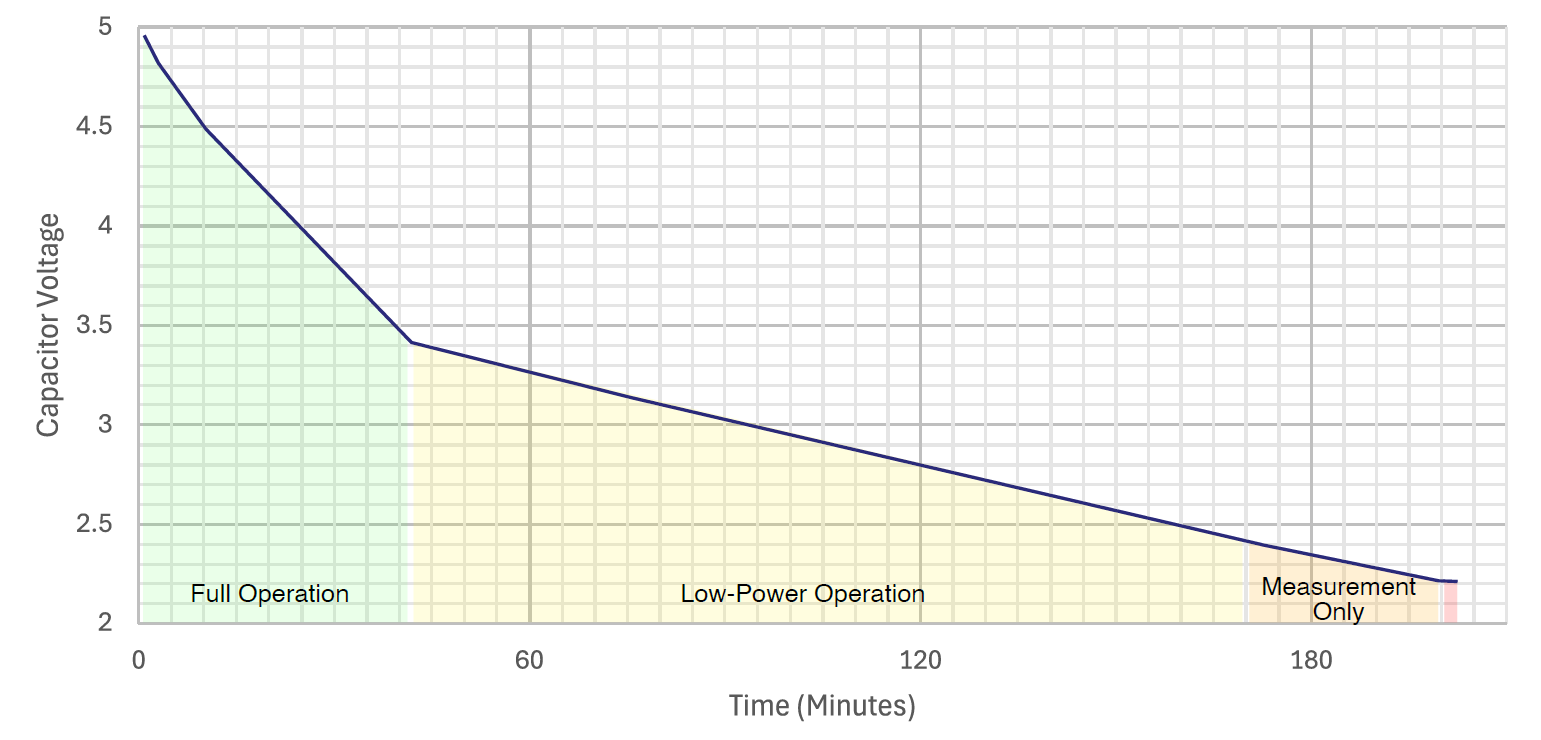
| State | Duration in State | Transmit Behavior |
|---|---|---|
| Full Operation | 42 minutes | 1 minute (configurable) |
| Low Power Operation | 128 minutes | 15 minutes |
| Measurement Only | 30 minutes | None |
| Total Until Shutdown | 200 minutes (3 hours, 20 minutes) | |