Conduit AP MTCAP Hardware Guide
This document applies to all models and regions on the device overview page. Go to https://multitech.com/all-products/cellular/cellular-gateways/conduit-ap/#models.
Document Part Number: S000835 Rev. 1.0
About the Conduit® AP
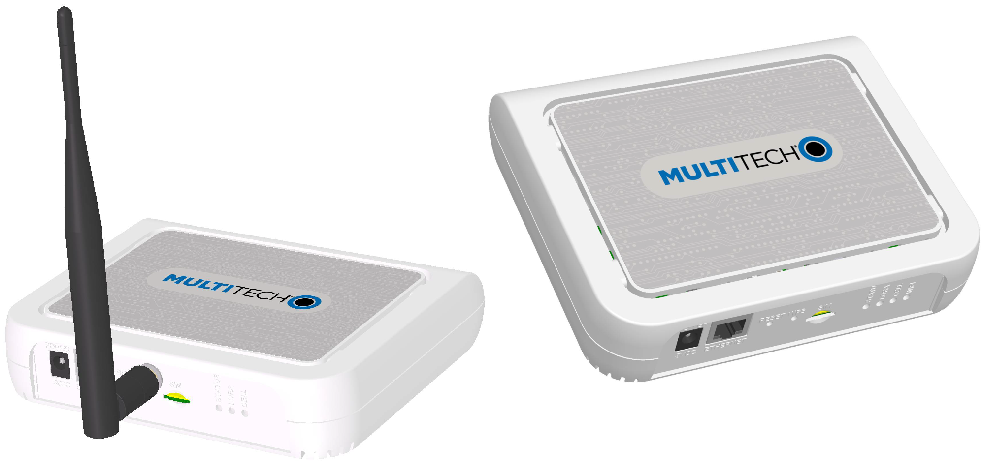
Conduit AP (MTCAP) securely connects thousands of LoRaWAN® wireless IoT sensors to the cloud using the LoRaWAN® protocol. The Conduit AP Access Point packet forwarding gateway offers Ethernet and Cellular Wide Area Networks seamless connectivity options to connect to Cloud based applications in centrally located data centers.
Package Contents
Your device ships with the following:
1 – Conduit AP Access Point
1 – 5 Volt, 2.5 Amp power supply
1 – RJ45 Ethernet cable
1 – LoRa antenna (based on model)
1 – Bumpon set (based on model)
1 – Mounting bracket
1 – Quick Start
MTCAP Ordering Options
To find information about ordering options, go to https://multitech.com/all-products/cellular/cellular-gateways/conduit-ap/#models.
Required Tools
The following tools are only required if mounting the device:
- Four #6 (3.5mm) screws with anchors (not provided)
- Screwdriver
- Drill
Safety Instructions
Operation Safety
ATTENTION: Lisez toutes les instructions et consignes de sécurité avant d'installer ou d'utiliser cet appareil.
- Follow all local laws, regulations, and rules for operating a wireless device.
- Use the device security features to block unauthorized use and theft.
- Unless otherwise noted, antennas are not approved for outdoor use. Do not extend any antenna outside of any building, dwelling, or campus.
- Do not attempt to disassemble the device. There are no user-serviceable parts inside.
- Do not misuse the device. Follow instructions on proper operation and only use as intended. Misuse could make the device inoperable, damage the device or other equipment, or harm users.
- Do not apply excessive pressure or place unnecessary weight on the device. This could result in damage to the device or harm to users.
- Do not use this device in explosive or hazardous environments unless the model is specifically approved for such use. The device may cause sparks. Sparks in explosive areas could cause an explosion or fire that may result in property damage, severe injury, or death.
- Do not expose the device to any extreme environment where the temperature or humidity is high. Such exposure could result in damage to the device or cause a fire. See the device specifications for recommended operating temperature and humidity.
- Do not expose the device to water, rain, or other liquids. It is not waterproof. Exposure to liquids could result in damage to the device.
- Using accessories, such as antennas, that MultiTech has not authorized or that are not compliant with the device accessory specifications may invalidate the warranty.
If the device is not working properly, contact MultiTech technical support.
Ethernet Ports
ATTENTION: Les ports Ethernet et de commande ne sont pas conçus pour être raccordés à un réseau de télécommunications public ou utilisé à l'extérieur du bâtiment.
Power Supply Caution
ATTENTION: Pour garantir une protection continue contre les risques d'incendie, remplacez les fusibles uniquement par des fusibles du même type et du même calibre. L'adaptateur doit être installé à proximité de l'appareil et doit être facilement accessible.
VORSICHT: Ersetzen Sie das Netzteil nicht durch ein Netzteil, das für ein anderes Produkt vorgesehen ist. Andernfalls kann das Modem beschädigt werden und Ihre Garantie erlischt. Der Adapter muss in der Nähe des Geräts installiert und leicht zugänglich sein.
UL Notice
UL Listed at 40° C, limited by power supply. UL Certification does not apply or extend to an ambient above 40° C and has not been evaluated by UL for ambient greater than 40° C. “UL has evaluated this device for use in ordinary locations only. Installation in a vehicle or other outdoor locations has not been evaluated by UL. UL Certification does not apply or extend to use in vehicles or outdoor applications or in ambient above 40° C.”
Spécifications UL
Listé UL à 40° C, limité par l'alimentation. La certification UL ne s'applique pas ou ne s'étend pas à des températures dépassant 40° C, et le produit n'a pas été évalué par UL pour une température ambiante dépassant 40° C. « UL a évalué cet appareil pour une utilisation en zone ordinaire uniquement. Le produit n'a pas été évalué par UL pour une installation dans un véhicule ou en extérieur. La certification UL ne s'applique pas ou ne s'étend pas aux applications dans un véhicule, en extérieur ou en présence d'une température ambiante supérieure à 40° C ».
General Safety
The device is designed for and intended to be used in fixed and mobile applications. Fixed means the device is physically secured at one location and cannot be easily moved to another location. Mobile means the device is used in other than fixed locations.
ATTENTION: Maintenir une distance d'au moins 23 cm (9 po) entre l'antenne du récepteur et le corps de l'utilisateur ou à proximité de personnes. Le modem n'est pas conçu pour, ou destinés à être utilisés dans les applications portables, moins de 23 cm (9 po) du corps de l'utilisateur.
Radio Frequency (RF) Safety
Due to the possibility of radio frequency (RF) interference, it is important that you follow any special regulations regarding the use of radio equipment. Follow the safety advice given below.
- Operating your device close to other electronic equipment may cause interference if the equipment is inadequately protected. Observe any warning signs and manufacturers’ recommendations.
- Different industries and businesses restrict the use of cellular devices. Respect restrictions on the use of radio equipment in fuel depots, chemical plants, or where blasting operations are in process. Follow restrictions for any environment where you operate the device.
- Do not place the antenna outdoors.
- Turn off your wireless device when in an aircraft. Using portable electronic devices in an aircraft may endanger aircraft operation, disrupt the cellular network, and may be illegal. Failing to observe this restriction may lead to suspension or denial of cellular services to the offender, legal action, or both.
- Turn off your wireless device when around gasoline or diesel‑fuel pumps and before filling your vehicle with fuel.
- Turn off your wireless device in hospitals and any other place where medical equipment may be in use.
Sécurité relative aux appareils à radiofréquence (RF)
À cause du risque d'interférences de radiofréquence (RF), il est important de respecter toutes les réglementations spéciales relatives aux équipements radio. Suivez les conseils de sécurité ci-dessous.
- Utiliser l'appareil à proximité d'autres équipements électroniques peut causer des interférences si les équipements ne sont pas bien protégés. Respectez tous les panneaux d'avertissement et les recommandations du fabricant.
- Certains secteurs industriels et certaines entreprises limitent l'utilisation des appareils cellulaires. Respectez ces restrictions relatives aux équipements radio dans les dépôts de carburant, dans les usines de produits chimiques, ou dans les zones où des dynamitages sont en cours. Suivez les restrictions relatives à chaque type d'environnement où vous utiliserez l'appareil.
- Ne placez pas l'antenne en extérieur.
- Éteignez votre appareil sans fil dans les avions. L'utilisation d'appareils électroniques portables en avion est illégale: elle peut fortement perturber le fonctionnement de l'appareil et désactiver le réseau cellulaires. S'il ne respecte pas cette consigne, le responsable peut voir son accès aux services cellulaires suspendu ou interdit, peut être poursuivi en justice, ou les deux.
- Éteignez votre appareil sans fil à proximité des pompes à essence ou de diesel avant de remplir le réservoir de votre véhicule de carburant.
- Éteignez votre appareil sans fil dans les hôpitaux ou dans toutes les zones où des appareils médicaux sont susceptibles d'être utilisés.
Interference with Pacemakers and Other Medical Devices
Radio frequency energy (RF) from cellular devices can interact with some electronic devices. This is electromagnetic interference (EMI). The FDA helped develop a detailed test method to measure EMI of implanted cardiac pacemakers and defibrillators from cellular devices. This test method is part of the Association for the Advancement of Medical Instrumentation (AAMI) standard. This standard allows manufacturers to ensure that cardiac pacemakers and defibrillators are safe from cellular device EMI.
The FDA continues to monitor cellular devices for interactions with other medical devices. If harmful interference occurs, the FDA will assess the interference and work to resolve the problem.
Precautions for Pacemaker Wearers
If EMI occurs, it could affect a pacemaker in one of three ways:
- Stop the pacemaker from delivering the stimulating pulses that regulate the heart's rhythm.
- Cause the pacemaker to deliver pulses irregularly.
- Cause the pacemaker to ignore the heart’s own rhythm and deliver pulses at a fixed rate.
Based on current research, cellular devices do not pose a significant health problem for most pacemaker wearers. However, people with pacemakers may want to take simple precautions to be sure that their device doesn't cause a problem.
- Keep the device on the opposite side of the body from the pacemaker to add extra distance between the pacemaker and the device.
- Avoid placing a turned-on device next to the pacemaker (for example, don’t carry the device in a shirt or jacket pocket directly over the pacemaker).
Specifications
LNA3 Specifications
| Category | Description |
|---|---|
| General | |
| Standards | LoRaWAN 1.0.2 specifications |
| LTE 3GPP Release 9 | |
| HSPA+ | |
| RAM | 256MB |
| Flash | 256MB |
| Radio Frequency | |
| ISM Band | 915 MHz ISM band for US and Canada |
| 4G/LTE | 1900 (B2) / AWS 1700 (B4) / 850 (B5) / 700 (B12/13) |
| 3G | 1900 (B2) / 850 (B5) |
| Physical Description | |
| Weight | 1.36 kg |
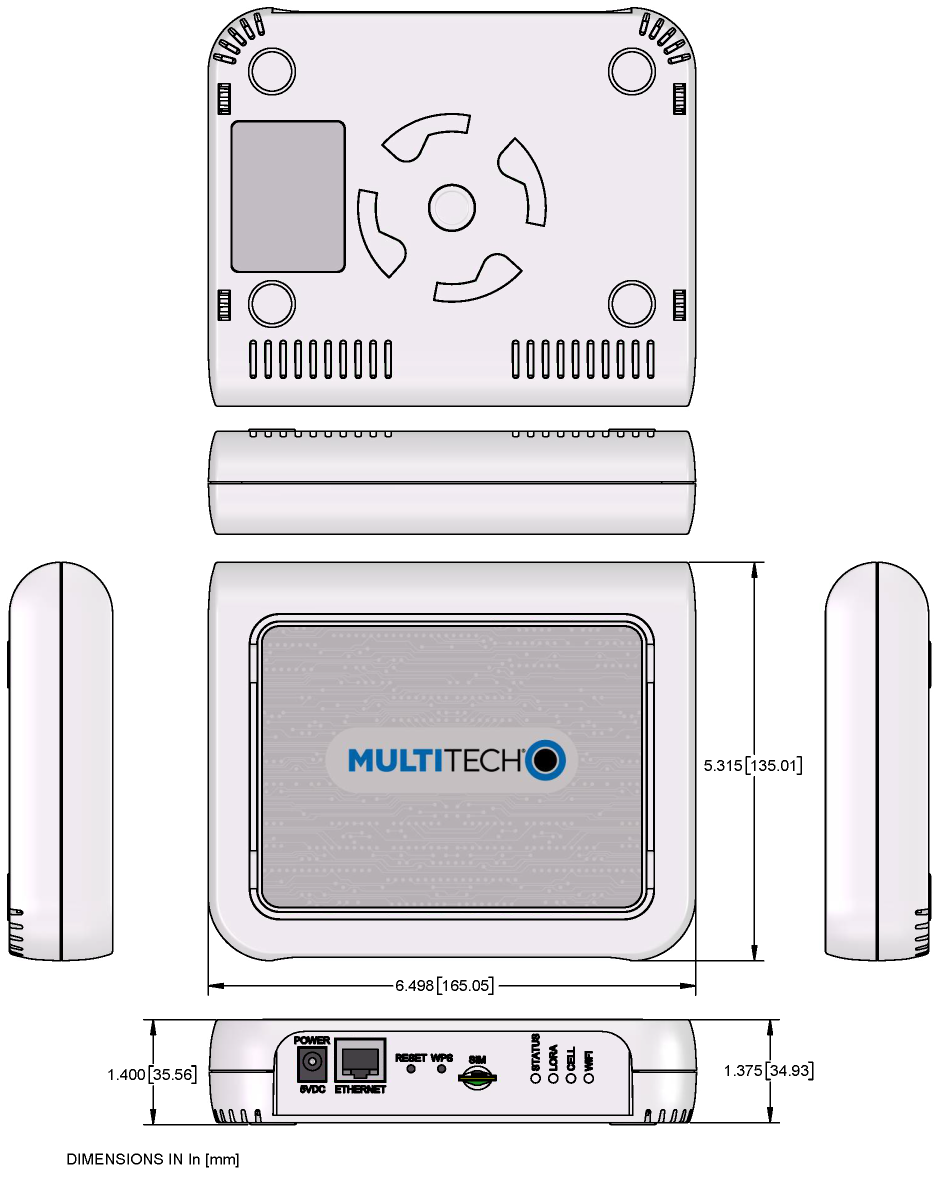
| Dimensions | Refer to Mechanical Drawings for Dimensions. |
| Chassis Type | PC-ABS |
| Environment | |
| Operating Temperature1 | -0° C to +70° C |
| Storage Temperature | -40° C to +85° C |
| Humidity | 20%-90% RH, non-condensing |
| Power Requirements | |
| Operating Voltage | 5Vdc, 1.4A |
| Certifications and Compliance | |
| EMC and Radio Compliance | FCC Part 15 Class B |
| FCC Part 15.247 (LoRa) | |
| FCC 22H, 24E, 27 | |
| Safety Compliance | UL 62368-1 2nd Ed |
| UL / IEC 62368-1 | |
| Approvals | AT&T, Verizon, T-Mobile, PTCRB |
1 UL listed at 40° C, limited by AC power supply. Product has been tested to +70° C excluding power supply.
L4E1 Specifications
| Category | Description |
|---|---|
| General | |
| Standards | LoRaWAN 1.0.2 specifications |
| LTE FDD Cat 4, 3GPP release compliant (-L4E1 models only) | |
| HSPA+ with GPRS fallback (-L4E1 models only) | |
| RAM | 256MB |
| Flash | 256MB |
| Radio Frequency | |
| ISM Band | 868 MHz ISM band for Europe |
| 4G/LTE | 4G: B1, B3, B7, B8, B20, B28A (-L4E1 models only) |
| 3G | 3G: B1, B3, B8 (-L4E1 models only) |
| 2G | 2G: B3, B8 (-L4E1 models only) |
| Physical Description | |
| Weight | 0.41 kg |
| Dimensions | Refer to Mechanical Drawings for Dimensions. |
| Chassis Type | PC-ABS |
| Environment | |
| Operating Temperature1 | -0° C to +70° C |
| Storage Temperature | -40° C to +85° C |
| Humidity | 20%-90% RH, non-condensing |
| Power Requirements | |
| Operating Voltage | 5Vdc, 1.4A |
| LoRa ERP2 | 13.3 dBm ERP for low power channels, maximum 14 dB. |
| 25.8 dB for high power channels, maximum 27 dB. | |
| Certifications and Compliance | |
| EMC and Radio Compliance | CE Mark, RED (EU) |
| Safety Compliance | UL/IEC 62368-1 |
1 UL listed at 40° C, limited by AC power supply. Product has been tested to +70° C excluding power supply.
2Determined using the internal LoRa antenna of 0.85 dB gain. If using an external LoRa antenna, adjust levels to ensure maximum values are not exceeded.
LAP3 Specifications
| Category | Description |
|---|---|
| General | |
| Standards | LoRaWAN 1.0.2 specifications |
| LTE FDD Cat.1, 3GPP release 10 compliant | |
| 3G fallback | |
| RAM | 256MB |
| Flash | 256MB |
| Radio Frequency | |
| ISM Band | 915 MHz ISM band for Australia |
| 4G/LTE | 2100 (B1) / 1800 (B3) / 850 (B5) / 800 (B8) / 700 (B28) |
| 3G | 2100 (B1) / 850 (B5) / 800 (B8) |
| Physical Description | |
| Weight | 1.36 kg |
| Dimensions | Refer to Mechanical Drawings for Dimensions. |
| Chassis Type | PC-ABS |
| Environment | |
| Operating Temperature1 | -0° C to +70° C |
| Storage Temperature | -40° C to +85° C |
| Humidity | 20%-90% RH, non-condensing |
| Power Requirements | |
| Operating Voltage | 5Vdc, 1.4A |
| Certifications and Compliance | |
| EMC and Radio Compliance | CISPR 32 |
| AS/NZS 4268:2017 | |
| Safety Compliance | RCM – Australia |
| UL/CSA 60950-1 | |
| IEC 60950-1 2nd Ed Am2 | |
| UL/CSA 62368-1 | |
| IEC 62368-1 | |
1 UL listed at 40° C, limited by AC power supply. Product has been tested to +70° C excluding power supply.
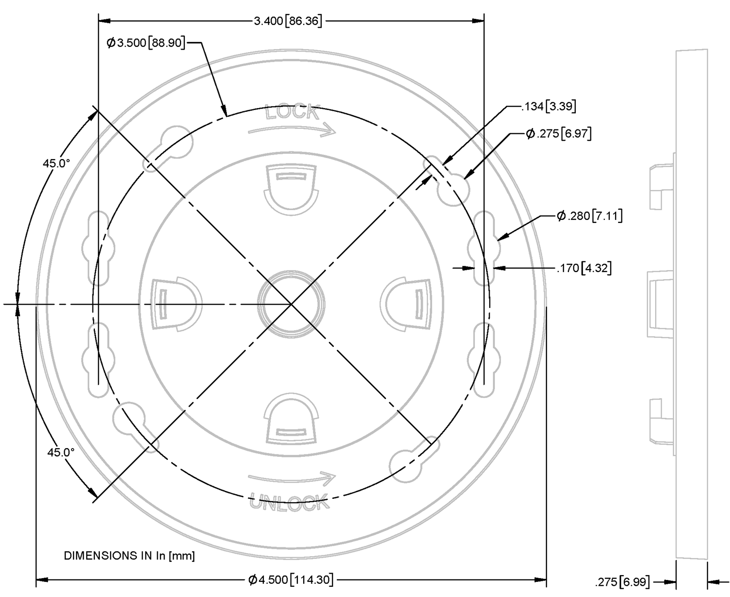
Device Dimensions
Models with External Antenna
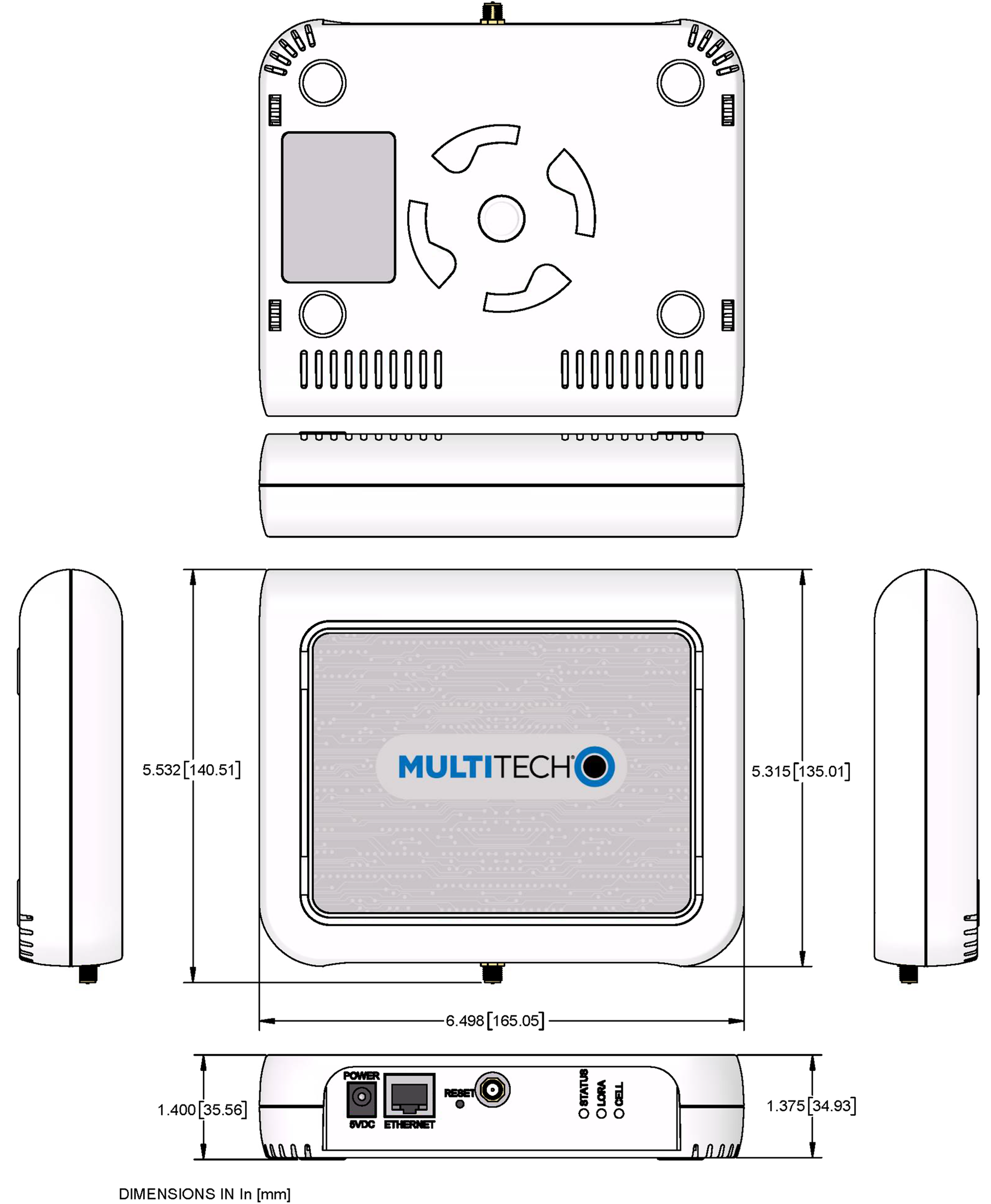
LoRa Models
MTCAP Labels
These are example labels. Actual labels vary depending on the regulatory approval markings and device model.
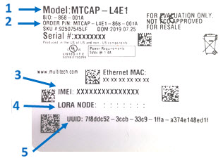
- MultiTech model identification
- MultiTech ordering part number
- IMEI (international mobile equipment identity) (cellular models only)
- Device node number
- UUID (universally unique identifier)
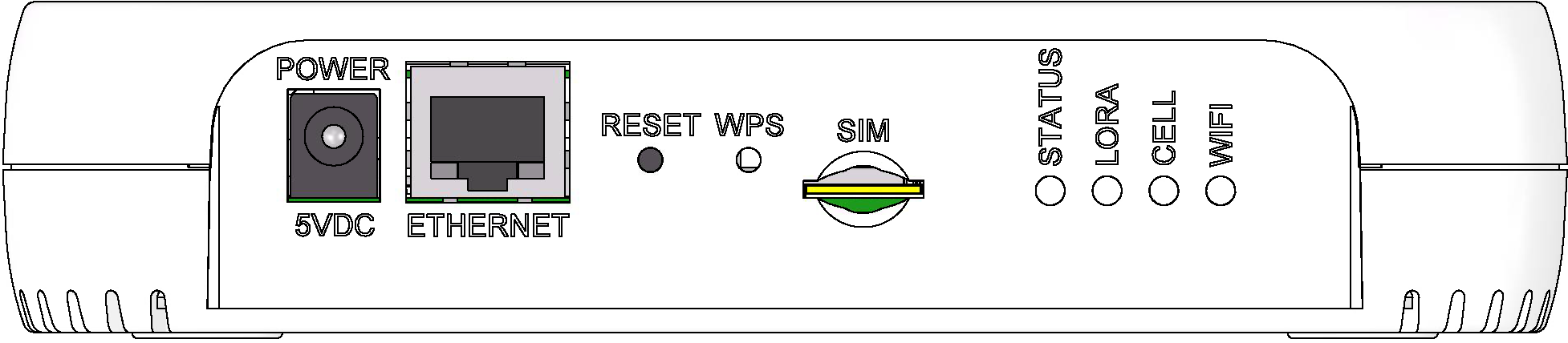
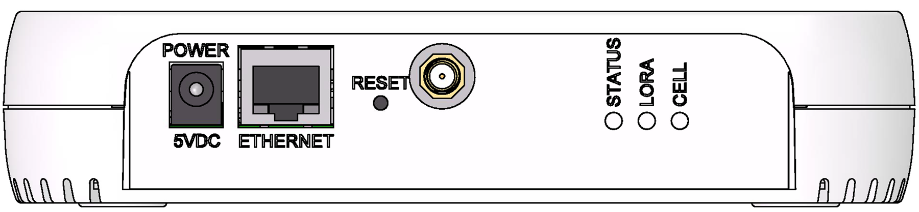
Connectors and LEDs
LoRa only models
LoRa and cellular radio models
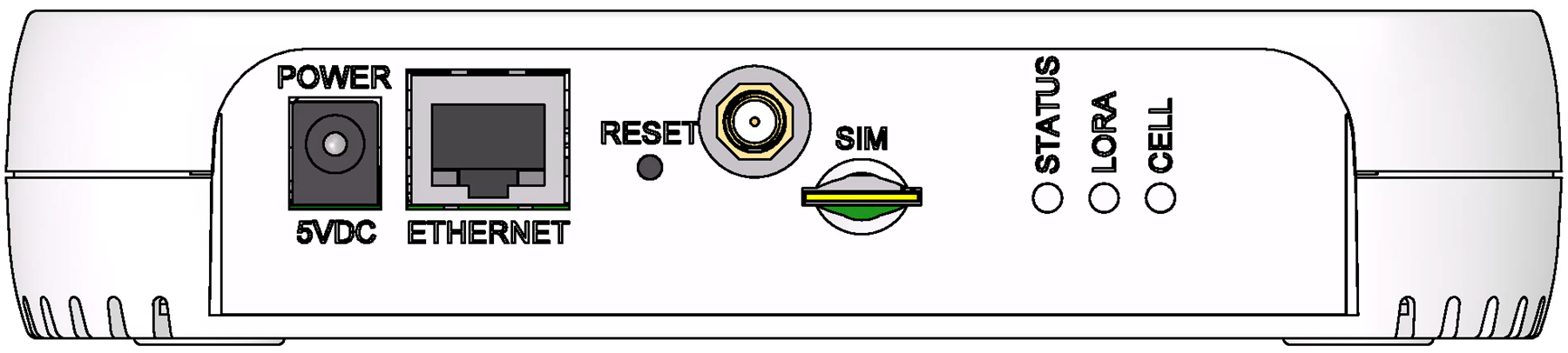
| Item | Description |
|---|---|
| Connectors | |
| Power | 5 Volt power jack. |
| Ethernet | RJ45 Ethernet jack. |
| Reset | Reset button. Reboots device or restores factory defaults. Refer to Resetting the Device for details. |
| WPS | Reserved for future use. |
| (No label) | Connector for external LoRa antenna. |
| SIM | Cellular models only. Micro (3FF) SIM slot. Refer to Installing SIM Card for details. |
| LEDs | |
| STATUS | Blinks when operating system is fully loaded. |
| LORA | Lights when LoRa software is active. |
| CELL | Cellular models only. Lights when there is power to the radio. Blinks when the SIM is registered with the carrier. |
| Ethernet Link | Left LED on the Ethernet connector. Blinks when data is sent or received on the Ethernet link. Steady light when there is a valid Ethernet connection. |
| Ethernet Speed | Right LED on the Ethernet connector. Lit when the Ethernet is linked at 100 Mbps. If not lit, the Ethernet is linked at 10 Mbps. |
Antenna
Your device ships with the following antenna. Contact MultiTech if you need a replacement antenna.
ISED Antenna Approval
This radio transmitter 125A-0058 has been approved by Innovation, Science and Economic Development Canada to operate with the antenna types listed below, with the maximum permissible gain indicated. Antenna types not included in this list that have a gain greater than the maximum gain indicated for any type listed are strictly prohibited for use with this device.
Le présent émetteur radio 125A-0058 a été approuvé par Innovation, Sciences et Développement économique Canada pour fonctionner avec les types d'antenne énumérés ci‑dessous et ayant un gain admissible maximal. Les types d'antenne non inclus dans cette liste, et dont le gain est supérieur au gain maximal indiqué pour tout type figurant sur la liste, sont strictement interdits pour l'exploitation de l'émetteur.
LoRa Antenna
| Manufacturer: | PulseLarsen Antenna |
| Description: | 868-928 MHz RP-SMA Antenna, 8" |
| Model Number: | W1063 |
MultiTech Ordering Part Numbers
| Ordering Part Number | Quantity |
|---|---|
| AN868-915A-1HRA | 1 |
| AN868-915A-10HRA | 10 |
| AN868-915A-50HRA | 50 |
Specifications
| Category | Description | |
|---|---|---|
| Frequency Range | 868-928 MHz | |
| Impedance | 50 Ohms | |
| VSWR | < 2.0 | |
| Gain | 1.0 dBi | |
| Radiation | Omni | |
| Polarization | Vertical | |
Power Measurements
MTCAP-LNA3-915
- Multi-Tech Systems, Inc. recommends that you incorporate a 10% buffer into the power source when determining product load.
- Maximum Power: The continuous current during maximum data rate with the radio transmitter at maximum power.
- Tx Pulse: The average peak current during an LTE connection.
- Inrush Charge: The total inrush charge at power on.
| Radio Protocol | Cellular Call Box Connection, No Data | Average Measured Current at Maximum Power | TX Pulse (AVG) Amplitude Current for GSM850 or Peak Current for LTE | Total Inrush Charge Measured in Millicoulomb | Total Inrush Duration |
|---|---|---|---|---|---|
| 5.0 Volts | |||||
| WCDMA | 195 mA | 1.18 A | 1.27 A | 1.19 mC | 1.28 mS |
| LTE | 192 mA | 1.05 A | 1.14 A | 1.19 mC | 1.28 mS |
- Multi-Tech Systems, Inc. recommends that you incorporate a 10% buffer into the power source when determining product load.
- Maximum Power: MTCAP LoRa connection to MTXDOT running TXP =20 and at+txdr=2. The MTXDOT was initialized to send packets by joining MTCAP and rapidly sending packet to the MTCAP.
- Tx Pulse: The average peak current.
- Inrush Charge: The total inrush charge at power on.
MTCAP-L4E1-868-xx
- Multi-Tech Systems, Inc. recommends that you incorporate a 10% buffer into the power source when determining product load.
- Maximum Power: The continuous current during maximum data rate with the radio transmitter at maximum power.
- Tx Pulse: The average peak current during a GSM850 transmission burst period or HSDPA/LTE connection. The transmission burst duration for GSM850 can vary, depending on what transmission scheme is being deployed (GPRS Class 8, Class 10, GSM, etc.).
- Inrush Charge: The total inrush charge at power on.
| Radio Protocol | Sleep Mode Current (If Applicable) | Cellular Call Box Connection, No Data | Average Measured Current at Maximum Power | TX Pulse (AVG) Amplitude Current for GSM850 or Peak Current for HSDPA/LTE | Total Inrush Charge Measured in Millicoulomb | Total Inrush Charge Duration During Power Up |
|---|---|---|---|---|---|---|
| 5.0 Volts | ||||||
| EGSM 900 MHz | NA | 222 mA | 760 mA | 2.06 Amps | 1.40 mC | 1.63 mS |
| WCDMA | NA | 225 mA | 1.18 Amps | 1.29 Amps | 1.40 mC | 1.63 mS |
| LTE | NA | 225 mA | 1.19 Amps | 1.30 Amps | 1.40 mC | 1.63 mS |
MTCAP-868-xx MTCAP-915-xx
- Multi-Tech Systems, Inc. recommends that you incorporate a 10% buffer into the power source when determining product load.
- Maximum Power: MTCAP LoRa connection to MTXDOT running TXP =20 and at+txdr=2. The MTXDOT was initialized to send packets by joining MTCAP and rapidly sending packet to the MTCAP.
- Tx Pulse: The average peak current.
- Inrush Charge: The total inrush charge at power on.
MTCAP-LAP3
- Multi-Tech Systems, Inc. recommends that you incorporate a 10% buffer into the power source when determining product load.
- Maximum Power: The continuous current during maximum data rate with the radio transmitter at maximum power.
- Tx Pulse: The average peak current during an LTE connection.
- Inrush Charge: The total inrush charge at power on.
| Radio Protocol | Cellular Call Box Connection, No Data | Average Measured Current at Maximum Power | TX Pulse (AVG) Amplitude Current for GSM850 or Peak Current for LTE | Total Inrush Charge Measured in Millicoulomb | Total Inrush Duration |
|---|---|---|---|---|---|
| 5.0 Volts | |||||
| WCDMA Band 1 | 189 mA | 867 mA | 1.00 A | 1.0 mC | 1.11 mS |
| LTE Band 1 | 191 mA | 1.26 mA | 1.33 A | 1.0 mC | 1.11 mS |
LoRa Transmission Output Power for MTAC-003
MTAC-003E00 (868 MHz)
Max output 24.5 dBm
| Power | Frequency | Bandwidth |
|---|---|---|
| 24.5 dBm | 869.525 MHz* | 125 kHz |
| 13.7 dBm | 868.95 MHz | 250 kHz |
*Note: Single-channel/high-power mode
MTAC-003U00 (915 MHz)
Max output 27.4 dBm
| Power | Frequency | Bandwidth |
|---|---|---|
| 27.4 dBm | 923.3 MHz | 500 kHz |
Before Installation
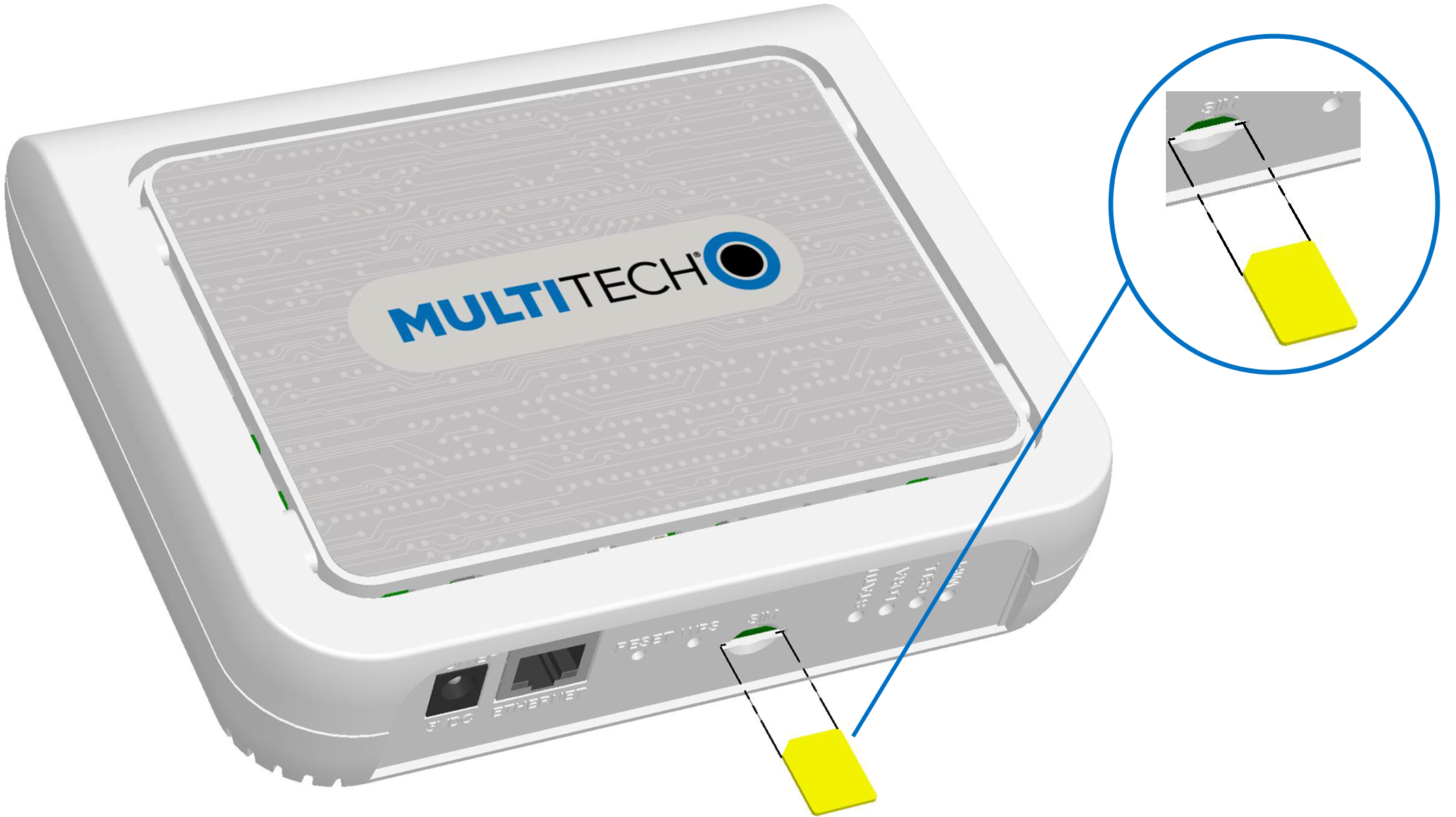
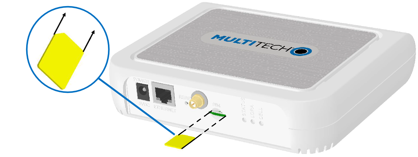
Installing a SIM Card
Models with cellular capability have a micro SIM slot, you'll need a micro (3FF) SIM card from your network provider.
To install the SIM card:
- With the contact side facing down, align the notched edge as shown and slide the SIM card completely into the SIM holder.
Removing a SIM Card
To remove the SIM card, push the SIM card in. The device ejects the SIM card.
Attaching the Antenna
(Models with external antenna only)
To connect the antenna:
- Finger-tighten the antenna to the antenna connector on your device.
Cabling the Device
To cable the device:
Ethernet only models with external LoRa antenna 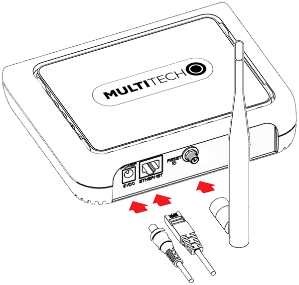 |
Ethernet only models, all internal antennas 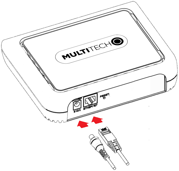 |
Cellular models with external LoRa antenna 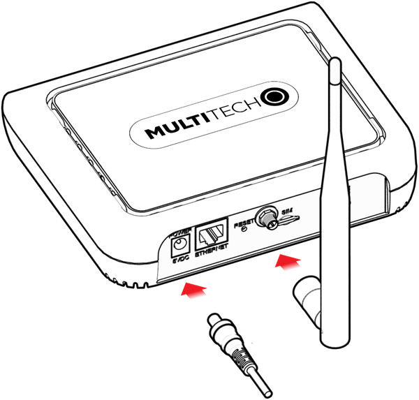 |
Cellular models, all internal antennas 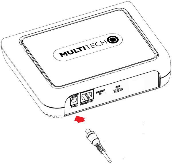 |
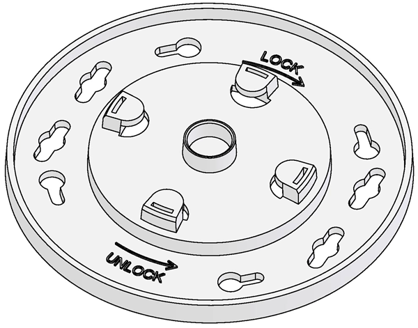
Mounting the Device
The device ships with a mounting bracket.
You will need
- Device
- Mounting bracket
- Four #6 (3.5mm) screws with anchors (not provided)
- Screwdriver
- Drill
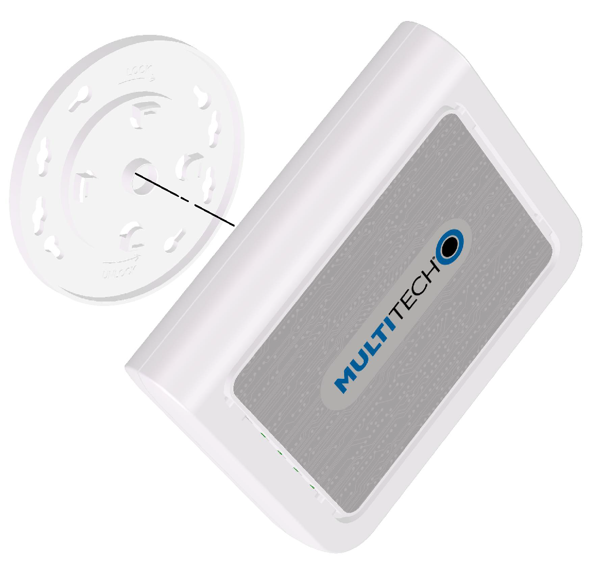
Mounting Bracket
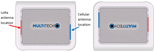
Determining Location
Follow these guidelines for best performance:
- The LoRa antenna is omnidirectional, but for best results, mount the device so the LoRa antenna is in a vertical position as shown in this section.
- For models with only internal LoRa antennas, place the device as high as possible, such as near the top of a wall.
- For models with external LoRa antennas, place the device at a level higher than the end devices.
- Select a location central to all devices to be connected to this device.
- Avoid obstructions. Important: Thick walls and reflective surfaces, such as metal, weaken the signal between the device and other devices.
- For models with only internal LoRa antennas, note the LoRa antenna
location in the following image. The LoRa signal will be strongest radiating
from that side of the device. The LoRa antenna is 31.2 mm long.

- We recommend conducting a site survey to test the signal strength in different locations before you mount the device.
Mounting the Device
- Determine where you want to mount the device.
- Mark where you want the screws to go.
- Drill holes for the screws and insert anchors.
- Place the mounting bracket and secure it with screws.
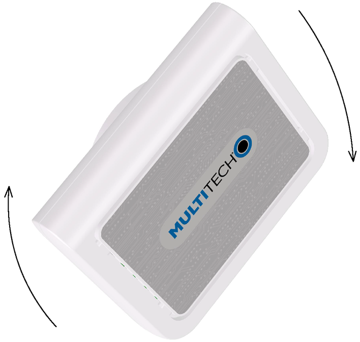
- Attach the device to the bracket and rotate until it locks into place.
|
 |
Models with Internal LoRa Antenna Only 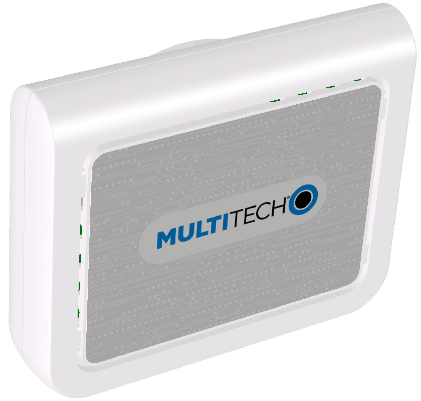 |
Models with External LoRa Antenna 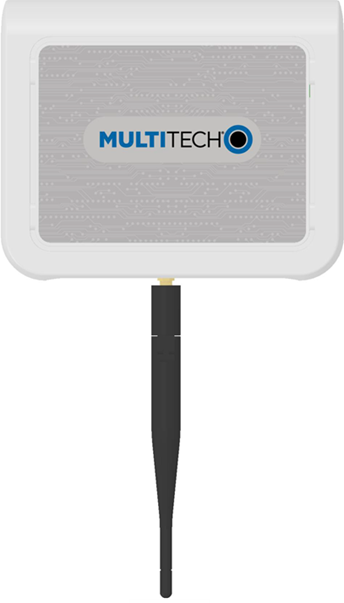 |
Installation
Getting Started
Setting Up Your Credentials (Commissioning) for mPower
The first time the device powers up, it goes into commissioning mode. The system requires you to set up an administrative user. To do this:
- Open a browser on your computer and enter the default IP address in the URL
field, 192.168.2.1. Most browsers display a warning about HTTP addresses
being unsafe because of a self-signed certificate:
- For Edge, click Advanced and then Continue to 192.168.2.1.
- For Firefox, click Advanced and then click Accept the Risk and Continue.
- For Chrome, click Advanced and then Continue to 192.168.2.1 (unsafe).
- Enter a username for the administrative user. Click OK. Follow on screen instructions for usernames.
- Enter a password and click OK. Follow on screen instructions for a secure password.
- Enter the password again to confirm. Click OK.
- Log into the device using the new username and password.
The First-Time Setup Wizard appears.
mPower Models First-Time Setup
If your device uses the mPower platform, refer to First-Time Setup in mPower Software Guide (S000727) for details. It is available through your model's page at https://multitech.com/all-products/cellular/cellular-gateways/conduit-ap/.
Connecting with LoRaWAN End Devices
For help connecting your device with LoRaWAN end devices, refer to Application Notes at https://multitech.com/all-products/cellular/cellular-gateways/conduit-ap/.
Operation
Reset the Device
The following is the default condition for the RESET button on the device. You can program a change to the behavior of the button if needed.
To reset the device:
- Find the hole labeled RESET. The Reset button is recessed into the case.
-
Use the pin to press and release the Reset button as follows:
- To reboot, press Reset for less than 3 seconds.
- To reboot and restore user-defined defaults (if previously set), press Reset for 3 to 29 seconds.
- To reset to factory settings, press Reset for
30 seconds or longer:
- The device restarts in commissioning mode. The system automatically removes all user accounts.
- Enter a new username and password to create your new administrative account. See User Accounts in the appropriate software guide for details on username and password requirements.
Disposal
Instructions for Disposal of WEEE by Users in the European Union
The symbol shown below is on the product or on its packaging, which indicates that this product must not be disposed of with other waste. Instead, it is the user's responsibility to dispose of their waste equipment by handing it over to a designated collection point for the recycling of waste electrical and electronic equipment. The separate collection and recycling of your waste equipment at the time of disposal will help to conserve natural resources and ensure that it is recycled in a manner that protects human health and the environment. For more information about where you can drop off your waste equipment for recycling, contact your local city office, your household waste disposal service or where you purchased the product.
|
July, 2005 |
Regulatory Information
FCC Notices
FCC 47 CFR Part 15 Regulation Class B Devices
This equipment has been tested and found to comply with the limits for a Class B digital device, pursuant to part 15 of the FCC Rules. These limits are designed to provide reasonable protection against harmful interference in a residential installation. This equipment generates, uses, and can radiate radio frequency energy and, if not installed and used in accordance with the instructions, may cause harmful interference to radio communications. However, there is no guarantee that interference will not occur in a particular installation.
If this equipment does cause harmful interference to radio or television reception, which can be determined by turning the equipment off and on, the user is encouraged to try to correct the interference by one or more of the following measures:
- Reorient or relocate the receiving antenna.
- Increase the separation between the equipment and receiver.
- Connect the equipment into an outlet on a circuit different from that to which the receiver is connected.
- Consult the dealer or an experienced radio/TV technician for help.
FCC Interference Notice
- This device may not cause harmful interference, and
- This device must accept any interference received, including interference that may cause undesired operation.
Industry Canada Class B Notice
This Class B digital apparatus meets all requirements of the Canadian Interference‑Causing Equipment Regulations.
This device complies with Industry Canada license‑exempt RSS standard(s). The operation is permitted for the following two conditions:
- The device may not cause interference, and
- This device must accept any interference, including interference that may cause undesired operation of the device.
Cet appareil numérique de la classe B respecte toutes les exigences du Reglement Canadien sur le matériel brouilleur.
Le présent appareil est conforme aux CNR d'Industrie Canada applicables aux appareils radio exempts de licence. L'exploitation est autorisée aux deux conditions suivantes:
- L'appareil ne doit pas produire de brouillage, et
- L'appareil doit accepter tout brouillage radioélectrique subi, même si le brouillage est susceptible d’en compromettre le fonctionnement.
EU EMC, Safety, and Radio Equipment Directive (RED) Compliance
![]() The CE mark is affixed to this product to confirm compliance with the following European Community Directives:
The CE mark is affixed to this product to confirm compliance with the following European Community Directives:
- Council Directive 2011/65/EU on the restriction of the use of certain hazardous substances in electrical and electronic equipment; and
- Council Directive 2014/53/EU on radio equipment and telecommunications terminal equipment and the mutual recognition of their conformity.
MultiTech declares that this device is in compliance with the essential requirements and other relevant provisions of Directive 2014/53/EU. The declaration of conformity may be downloaded at https://multitech.com/product-support/.
Australia Regulatory Compliance Mark (RCM)
![]() This product complies with the requirements of the
Regulatory Compliance Mark (RCM) for Electrical Regulatory Authorities Council (ERAC),
Electrical Equipment Safety System (EESS), and the Australian Communications and Media
Authority (ACMA) for Electromagnetic Compatibility (EMC).
This product complies with the requirements of the
Regulatory Compliance Mark (RCM) for Electrical Regulatory Authorities Council (ERAC),
Electrical Equipment Safety System (EESS), and the Australian Communications and Media
Authority (ACMA) for Electromagnetic Compatibility (EMC).
Brazil Regulatory Information
Este equipamento nao tem direito a protecao contra interferencia prejudicial e nao pode causar interferencia em sistemas devidamente autorizados.
Para maiores informacoes, consulte o site da ANATEL www.gov.br/anatel/pt-br.
Environmental Notices
EU WEEE Directive
The Waste from Electrical and Electronic Equipment (WEEE) Directive places an obligation on EU‑based manufacturers, distributors, retailers, and importers to take back electronics products at the end of their useful life. A sister directive, ROHS (Restriction of Hazardous Substances) complements the WEEE Directive by banning the presence of specific hazardous substances in the products at the design phase. The WEEE Directive covers all MultiTech products imported into the EU as of August 13, 2005. EU‑based manufacturers, distributors, retailers and importers are obliged to finance the costs of recovery from municipal collection points, reuse, and recycling of specified percentages per the WEEE requirements.
EU RoHS 3 Directive
MultiTech confirms that all products comply with the chemical concentration limitations set forth in the Restriction of Hazardous Substances in Electrical and Electronic Equipment (RoHS 3) regulations for CE and UKCA, following the standard EN IEC 63000:2018.
For the current Certificate of Compliance for Hazardous Substances and additional regulatory documents, go to https://multitech.com/approvals-and-certifications/.
EU REACH‑SVHC Statement
Multi‑Tech Systems, Inc. confirms that none of its products or packaging contain any of the Substances of Very High Concern (SVHC) on the REACH Candidate List, in a concentration above the 0.1% by weight allowable limit.
For the current REACH‑SVHC statement and additional regulatory documents, go to https://multitech.com/approvals-and-certifications/.
Accessories
To find information on accessories for your product, go to https://multitech.com/all-products/accessories/.
Related Documents
Additional documentation is available at www.multitech.com. Search for the document part number in the website search.
| Document | Description | Part Number |
|---|---|---|
| mPower Software Guide | For mPower models only. Includes steps for configuring and using devices using the mPower platform. | S000727 |
| Conduit AP MTCAP, MTCAP2, and MTCAP3 Quick-start guide | Steps for getting started with hardware. Ships with the device is available online. Go to https://multitech.com/wp-content/uploads/82104753L_MTCAP-MTCAP2-MTCAP3_Quick-Start.pdf. | N/A |
| Telit LE910 AT Commands Reference Guide | For LNA devices, lists AT Commands and parameters used to communicate with your device. | 80407ST10116A |
Developer Documentation
Our developer site includes information for the mLinux platform, advanced mPower information, and LoRa information.
- For mLinux getting started and advanced information, go to http://www.multitech.net/developer/software/mlinux/.
- For advanced mPower information, go to http://www.multitech.net/developer/software/aep/.
- For LoRa information, go to http://www.multitech.net/developer/software/lora/.