
MultiConnect® microCell User Guide
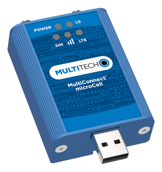
About the MultiConnect® microCell USB Cellular Modems
The MultiConnect microCell is a compact and simple communications platform that provides cellular capabilities for fixed and mobile applications. It is intended for use in settings such as vending, smart parking, medical, smart inventory tracking equipment and commercial applications.
MTCM2 Build Options
| Ordering Part Number | Description | Region |
|---|---|---|
| MTCM2-L4G1D-B03-KIT | LTE Cat 4 USB Modem with Accessory Kit | Global |
| MTCM2-L4G1-B03-KIT | LTE Cat 4 USB Modem with Accessory Kit | Europe |
| MTCM2-L6G1-B03-KIT | Private LTE CBRS OnGo Cat 6 USB Modem with Accessory Kit | USA |
Safety Instructions
Operation Safety
ATTENTION: Lisez toutes les instructions et consignes de sécurité avant d'installer ou d'utiliser cet appareil.
- Follow all local laws, regulations, and rules for operating a wireless device.
- Use the device security features to block unauthorized use and theft.
- Unless otherwise noted, antennas are not approved for outdoor use. Do not extend any antenna outside of any building, dwelling, or campus.
- Do not attempt to disassemble the device. There are no user-serviceable parts inside.
- Do not misuse the device. Follow instructions on proper operation and only use as intended. Misuse could make the device inoperable, damage the device or other equipment, or harm users.
- Do not apply excessive pressure or place unnecessary weight on the device. This could result in damage to the device or harm to users.
- Do not use this device in explosive or hazardous environments unless the model is specifically approved for such use. The device may cause sparks. Sparks in explosive areas could cause an explosion or fire that may result in property damage, severe injury, or death.
- Do not expose the device to any extreme environment where the temperature or humidity is high. Such exposure could result in damage to the device or cause a fire. See the device specifications for recommended operating temperature and humidity.
- Do not expose the device to water, rain, or other liquids. It is not waterproof. Exposure to liquids could result in damage to the device.
- Using accessories, such as antennas, that MultiTech has not authorized or that are not compliant with the device accessory specifications may invalidate the warranty.
If the device is not working properly, contact MultiTech technical support.
Power Supply Caution
ATTENTION: Pour garantir une protection continue contre les risques d'incendie, remplacez les fusibles uniquement par des fusibles du même type et du même calibre. L'adaptateur doit être installé à proximité de l'appareil et doit être facilement accessible.
VORSICHT: Ersetzen Sie das Netzteil nicht durch ein Netzteil, das für ein anderes Produkt vorgesehen ist. Andernfalls kann das Modem beschädigt werden und Ihre Garantie erlischt. Der Adapter muss in der Nähe des Geräts installiert und leicht zugänglich sein.
General Safety
The device is designed for and intended to be used in fixed and mobile applications. Fixed means the device is physically secured at one location and cannot be easily moved to another location. Mobile means the device is used in other than fixed locations.
ATTENTION: Maintenir une distance d'au moins 23 cm (9 po) entre l'antenne du récepteur et le corps de l'utilisateur ou à proximité de personnes. Le modem n'est pas conçu pour, ou destinés à être utilisés dans les applications portables, moins de 23 cm (9 po) du corps de l'utilisateur.
Radio Frequency (RF) Safety
Due to the possibility of radio frequency (RF) interference, it is important that you follow any special regulations regarding the use of radio equipment. Follow the safety advice given below.
- Operating your device close to other electronic equipment may cause interference if the equipment is inadequately protected. Observe any warning signs and manufacturers’ recommendations.
- Different industries and businesses restrict the use of cellular devices. Respect restrictions on the use of radio equipment in fuel depots, chemical plants, or where blasting operations are in process. Follow restrictions for any environment where you operate the device.
- Do not place the antenna outdoors.
- Turn off your wireless device when in an aircraft. Using portable electronic devices in an aircraft may endanger aircraft operation, disrupt the cellular network, and may be illegal. Failing to observe this restriction may lead to suspension or denial of cellular services to the offender, legal action, or both.
- Turn off your wireless device when around gasoline or diesel‑fuel pumps and before filling your vehicle with fuel.
- Turn off your wireless device in hospitals and any other place where medical equipment may be in use.
Sécurité relative aux appareils à radiofréquence (RF)
À cause du risque d'interférences de radiofréquence (RF), il est important de respecter toutes les réglementations spéciales relatives aux équipements radio. Suivez les conseils de sécurité ci-dessous.
- Utiliser l'appareil à proximité d'autres équipements électroniques peut causer des interférences si les équipements ne sont pas bien protégés. Respectez tous les panneaux d'avertissement et les recommandations du fabricant.
- Certains secteurs industriels et certaines entreprises limitent l'utilisation des appareils cellulaires. Respectez ces restrictions relatives aux équipements radio dans les dépôts de carburant, dans les usines de produits chimiques, ou dans les zones où des dynamitages sont en cours. Suivez les restrictions relatives à chaque type d'environnement où vous utiliserez l'appareil.
- Ne placez pas l'antenne en extérieur.
- Éteignez votre appareil sans fil dans les avions. L'utilisation d'appareils électroniques portables en avion est illégale: elle peut fortement perturber le fonctionnement de l'appareil et désactiver le réseau cellulaires. S'il ne respecte pas cette consigne, le responsable peut voir son accès aux services cellulaires suspendu ou interdit, peut être poursuivi en justice, ou les deux.
- Éteignez votre appareil sans fil à proximité des pompes à essence ou de diesel avant de remplir le réservoir de votre véhicule de carburant.
- Éteignez votre appareil sans fil dans les hôpitaux ou dans toutes les zones où des appareils médicaux sont susceptibles d'être utilisés.
Interference with Pacemakers and Other Medical Devices
Radio frequency energy (RF) from cellular devices can interact with some electronic devices. This is electromagnetic interference (EMI). The FDA helped develop a detailed test method to measure EMI of implanted cardiac pacemakers and defibrillators from cellular devices. This test method is part of the Association for the Advancement of Medical Instrumentation (AAMI) standard. This standard allows manufacturers to ensure that cardiac pacemakers and defibrillators are safe from cellular device EMI.
The FDA continues to monitor cellular devices for interactions with other medical devices. If harmful interference occurs, the FDA will assess the interference and work to resolve the problem.
Precautions for Pacemaker Wearers
If EMI occurs, it could affect a pacemaker in one of three ways:
- Stop the pacemaker from delivering the stimulating pulses that regulate the heart's rhythm.
- Cause the pacemaker to deliver pulses irregularly.
- Cause the pacemaker to ignore the heart’s own rhythm and deliver pulses at a fixed rate.
Based on current research, cellular devices do not pose a significant health problem for most pacemaker wearers. However, people with pacemakers may want to take simple precautions to be sure that their device doesn't cause a problem.
- Keep the device on the opposite side of the body from the pacemaker to add extra distance between the pacemaker and the device.
- Avoid placing a turned-on device next to the pacemaker (for example, don’t carry the device in a shirt or jacket pocket directly over the pacemaker).
Specifications
MTCM2-L4G1D-B03 Specifications
| Category | Description |
|---|---|
| General | |
| Standards | 3GPP Rel. 11 LTE |
| UMTS/HSPA+ | |
| GSM/GPRS/EDGE | |
| USB Interface is CDC-ACM compliant | |
| TCP/IP Functions | FTP, SMTP, SSL, TCP, UDP |
| Frequency Bands | LTE FDD: B1/B2/B3/B4/B5/B7/B8/B12/B13/B18/ B19/B20/B25/B26/B28 |
| LTE TDD: B38/B39/B40/B41 | |
| WCDMA: B1/B2/B4/B5/B6/B8/B19 | |
| GSM: B2/B3/B5/B8 | |
| Speed | |
| Data Speed | LTE FDD: Max 150Mbps (DL)/Max 50Mbps (UL) |
| LTE TDD: Max 130Mbps (DL)/Max 35Mbps (UL) | |
| UMTS: DC-HSDPA: Max 42Mbps (DL) | |
| UMTS: HSUPA: Max 5.76Mbps (UL) | |
| UMTS: WCDMA: Max 384Kbps (DL)/Max 384Kbps (UL) | |
| GSM: EDGE: Max 296Kbps (DL)/Max 236.8Kbps (UL) | |
| GSM: GPRS: Max 107Kbps (DL)/Max 85.6Kbps (UL) | |
| Physical Description | |
| Weight | Device only 2.4 oz (66 g); With antennas 2.9 oz (83 g) |
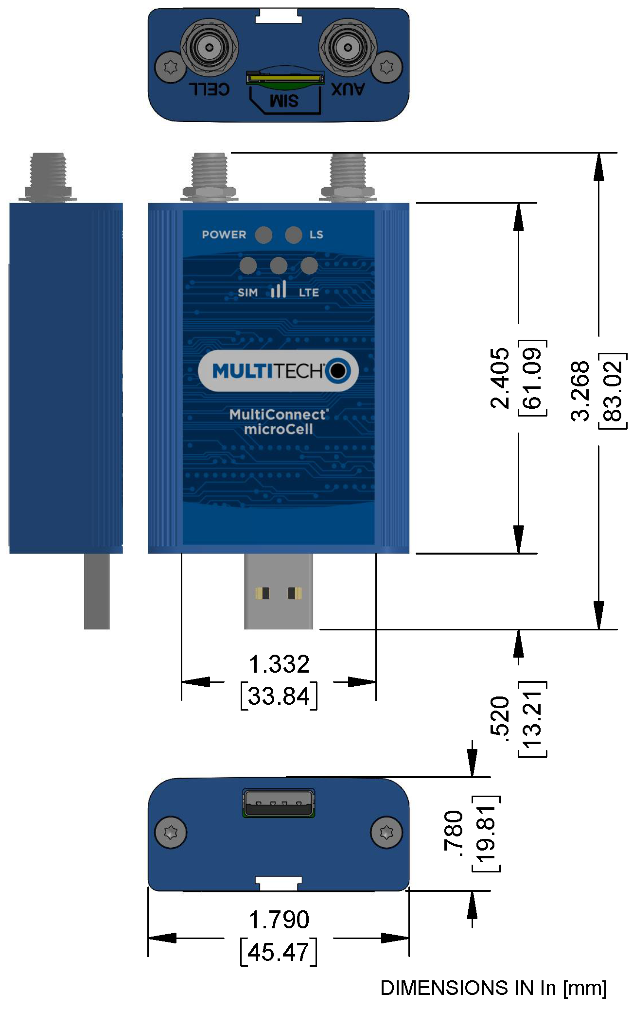
| Dimensions | Refer to mechanical drawing for dimensions. |
| Connectors | |
| Antenna Connector | 2 SMA connectors for cellular |
| SIM | 1.8V and 3V SIM holder for micro-SIM (3FF) card |
| USB | USB 2.0 with High Speed up to 480 Mbps |
| Environment | |
| Operating Temperature | -40° C to +85° C* |
| Storage Temperature | -40° C to +85° C |
| Humidity | 20%-90% RH, non-condensing |
| Power Requirements | |
| Operating Voltage | USB Model: 5 VDC |
| SMS | |
| SMS | Point-to-Point messaging |
| Mobile-Terminated SMS | |
| Mobile-Originated SMS | |
| Certifications and Compliance | |
| EMC and Radio Compliance | CE Mark, RED (EU), FCC, RCM, IC |
| Safety Compliance | IEC 60950-1 2nd ED, IEC 62368-1 |
| Carrier | PTCRB, AT&T, T-Mobile, Verizon |
*UL tested to ambient temperature of +60C.
MTCM2-L6G1 Specifications
| Category | Description |
|---|---|
| General | |
| Standards | 3GPP E-UTRA Release 10 |
| USB Interface is CDC-ACM and CDC-ETHER compliant | |
| TCP/IP Functions | FTP, SMTP, SSL, UDP |
| Frequency Bands | LTE: B42/B43 |
| CBRS: B48 | |
| Speed | |
| Data Speed | LTE: Max 200Mbps (DL)/Max 15Mbps (UL) |
| Physical Description | |
| Weight | Device only 2.4 oz (66 g); With antennas 2.9 oz (83 g) |
| Dimensions | Refer to Dimensions for dimensions. |
| Connectors | |
| Antenna Connector | 2 SMA connectors |
| SIM | 1.8V and 3V SIM holder for micro-SIM (3FF) card |
| USB | USB 2.0 with High Speed up to 480 Mbps |
| Environment | |
| Operating Temperature | -30° C to +60° C* |
| Storage Temperature | -40° C to +85° C |
| Operating Humidity | 10%-85% RH, non-condensing |
| Storage Humidity | 5%-85% RH, non-condensing |
| Power Requirements | |
| Operating Voltage | USB Model: 5 VDC |
| SMS | |
| SMS | Point-to-Point messaging |
| Mobile-Terminated SMS | |
| Mobile-Originated SMS | |
| Certifications and Compliance | |
| EMC and Radio Compliance | FCC Part 15B |
| FCC Part 96.47 | |
| Safety Compliance | UL/cUL 62368-1 |
*UL tested to ambient temperature of +60C.
MTCM2-L4G1 Specifications
| Category | Description |
|---|---|
| General | |
| Standards | 3GPP Rel. 11 LTE |
| UMTS/HSPA+ | |
| GSM/GPRS/EDGE | |
| USB Interface is CDC-ACM compliant | |
| TCP/IP Functions | FTP, SMTP, SSL, TCP, UDP |
| Frequency Bands | LTE FDD: B1/B2/B3/B4/B5/B7/B8/B12/B13/B18/ B19/B20/B25/B26/B28 |
| LTE TDD: B38/B39/B40/B41 | |
| WCDMA: B1/B2/B4/B5/B8/B6/B19 | |
| GSM: B2/B3/B5/B8 | |
| Speed | |
| Data Speed | LTE FDD: Max 150Mbps (DL)/Max 50Mbps (UL) |
| LTE TDD: Max 130Mbps (DL)/Max 35Mbps (UL) | |
| UMTS: DC-HSDPA: Max 42Mbps (DL) | |
| UMTS: HSUPA: Max 5.76Mbps (UL) | |
| UMTS: WCDMA: Max 384Kbps (DL)/Max 384Kbps (UL) | |
| GSM: EDGE: Max 296Kbps (DL)/Max 236.8Kbps (UL) | |
| GSM: GPRS: Max 107Kbps (DL)/Max 85.6Kbps (UL) | |
| Physical Description | |
| Weight | Device only 2.4 oz (66 g); With antennas 2.9 oz (83 g) |
| Dimensions | Refer to mechanical drawing for dimensions. |
| Connectors | |
| Antenna Connector | 2 SMA connectors for cellular |
| SIM | 1.8V and 3V SIM holder for micro-SIM (3FF) card |
| USB | USB 2.0 with High Speed up to 480 Mbps |
| Environment | |
| Operating Temperature | -40° C to +85° C* |
| Storage Temperature | -40° C to +85° C |
| Humidity | 20%-90% RH, non-condensing |
| Power Requirements | |
| Operating Voltage | USB Model: 5 VDC |
| SMS | |
| SMS | Point-to-Point messaging |
| Mobile-Terminated SMS | |
| Mobile-Originated SMS | |
| Certifications and Compliance | |
| EMC and Radio Compliance | CE Mark, RED (EU) |
| Safety Compliance | IEC 60950-1 2nd ED, IEC 62368-1 |
*UL tested to ambient temperature of +60C.
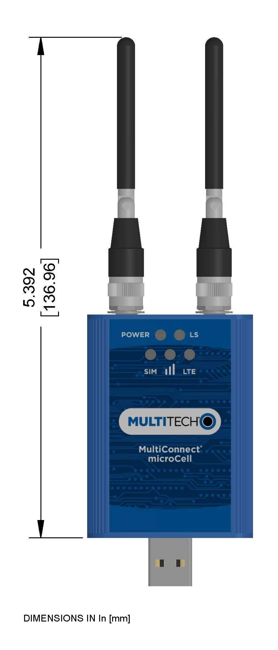
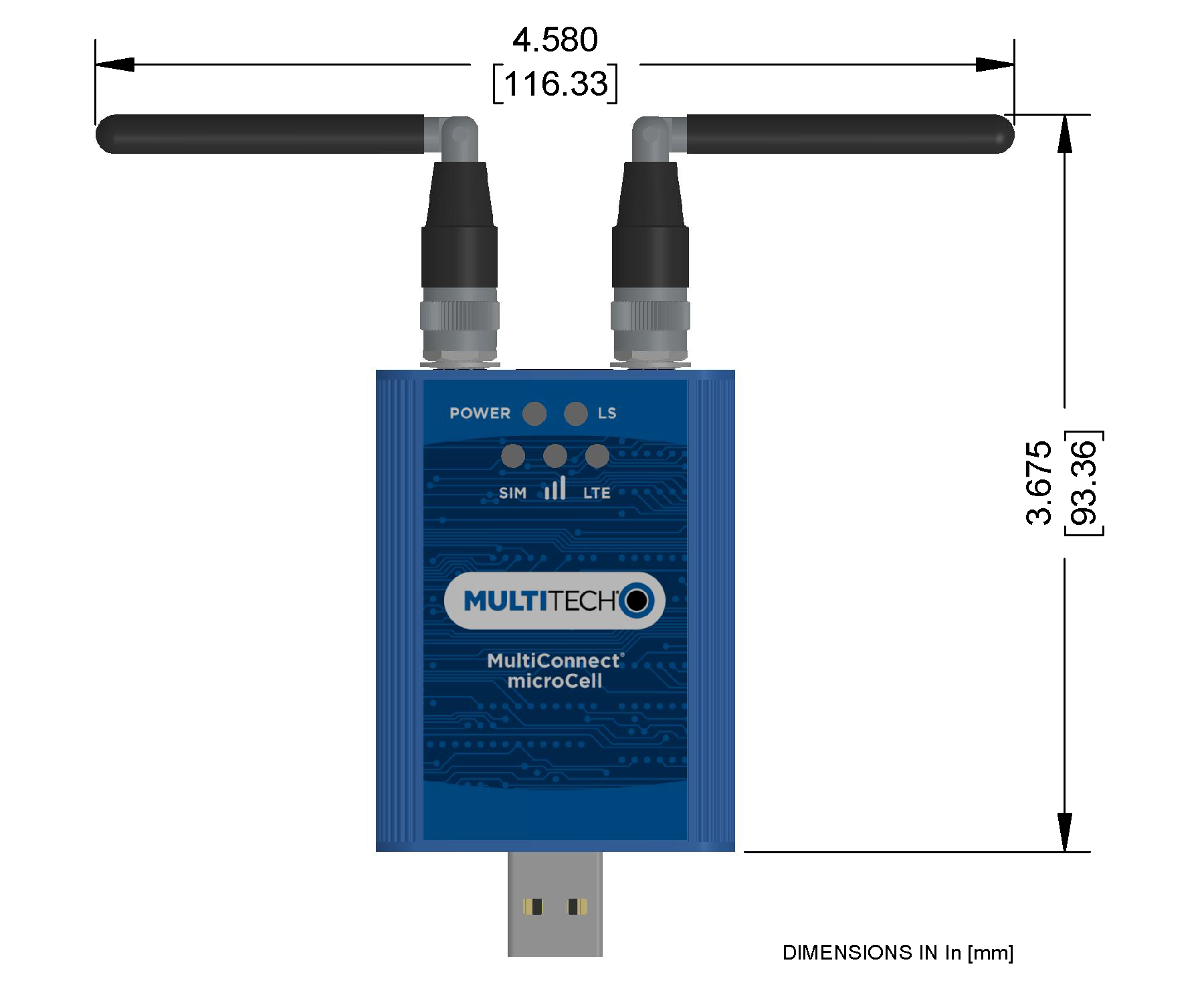
MTCM2-L4G1D-B03 Dimensions
 |
 |
 |
MTCM2-L6G1 Dimensions
|
|
|
MTCM2-L4G1 Dimensions
|
|
|
Side Panels and Connectors
Side Panels

Connectors
The device has the following connectors:
- USB 1 USB connector
- SMA 2 female SMA connectors, labeled CELL and AUX
- SIM 1 micro-SIM slot, between the SMA connectors
LED Descriptions
The MTCM2 has the following LEDs:

- Slow is 1 second on 1 second off
- Fast is 200 milliseconds on 200 milliseconds off
| LED | Status | Description |
|---|---|---|
| Power | On | Device has power |
| Off | Device does not have power | |
| Link Status (LS) | On | Radio is not registered |
| Flash Slow | Registered | |
| Off | Radio is turned off, in PSM mode, receiving a firmware update, or SIM is not inserted. | |
| LTE | On | LTE |
| Off | SIM not inserted or radio technology unknown | |
| SIM | On | Ready |
| Flash Slow | Other | |
| Off | SIM not inserted | |
Signal Strength  |
On | Good |
| Flash Fast | Fair | |
| Flash Slow | Poor | |
| Off | Too low for communication or SIM not inserted. |

Additional Signal LED Information
Signal LED is based on +CESQ RSRP and RSRQ:
| RSRP | RSRQ | |
|---|---|---|
| On | -110 | -9 |
| Fast | -105 | -11 to -15 |
| Slow | -120 | -16 to -19 |
| Off | < -120 | < -19 |
Power Measurements
Multi-Tech Systems, Inc. recommends incorporating a 10% buffer into your power source when determining product load.
MTCM2-L4G1D-B03 Power Draw
| Radio Protocol | Live Connection, Idle Current | Cellular Connection Idle, No Data | Measured Current at Max Power1 | TX Pulse Amplitude Current for Peak Current 2 | Total Inrush Charge 3 | Total Inrush Duration During Power Up |
|---|---|---|---|---|---|---|
| 5 Volts | ||||||
| GSM850 | 67 mA | 67 mA | 354 mA | 1.40 A | 0.156 mC | 26.1 uS |
| WCDMA Band 2 (1854MHz) | 68 mA | 67 mA | 512 mA | 580 mA | 0.156 mC | 26.1 uS |
| LTE Band 1 (1950MHz) | 71 mA | 68 mA | 721 mA | 788 mA | 0.156 mC | 26.1 uS |
- Maximum Power: The continuous current during maximum data rate with the radio transmitter at maximum power.
- TX Pulse: The average peak current during an HSDPA/LTE connection.
- Inrush Charge: The total inrush charge at power on.
MTCM2-L6G1 Power Draw
| Radio Protocol | 3G On/Off Mode Current or Sleep Mode | Live Connection, Idle Current | Average Measured Current at Max Power1 | TX Pulse Amplitude Current for Peak Current 2 | Total Inrush Charge 3 | Total Inrush Duration During Power Up |
|---|---|---|---|---|---|---|
| 5 Volts USB | ||||||
| LTE Band 43 (3700Mhz) | N/A | N/A | 477 mA | 784 mA | 0.135 mC | 22.1 uS |
| LTE Band 42 (3500Mhz) | N/A | N/A | 482 mA | 792 mA | 0.135 mC | 22.1 uS |
| LTE Band 48 (3625Mhz) | N/A | 173 mA | 473 mA | 768 mA | 0.135 mC | 22.1 uS |
- Maximum Power: The continuous current during maximum data rate with the radio transmitter at maximum power.
- TX Pulse: The average peak current during an LTE connection.
- Inrush Charge: The total inrush charge at power on.
MTCM2-L4G1D Power Draw
| Radio Protocol | 3G On/Off Mode Current or Sleep Mode | Live Connection, Idle Current | Cellular Connection Idle, No Data | Measured Current at Max Power1 | TX Pulse Amplitude Current for Peak Current 2 | Total Inrush Charge 3 | Total Inrush Duration During Power Up |
|---|---|---|---|---|---|---|---|
| 5 Volts | |||||||
| GSM850 | N/A | 67 mA | 67 mA | 354 mA | 1.40 A | 0.156 mC | 26.1 uS |
| WCDMA Band 2 (1854MHz) | N/A | 68 mA | 67 mA | 512 mA | 580 mA | 0.156 mC | 26.1 uS |
| LTE Band 1 (1950MHz) | N/A | 71 mA | 68 mA | 721 mA | 788 mA | 0.156 mC | 26.1 uS |
- Maximum Power: The continuous current during maximum data rate with the radio transmitter at maximum power.
- TX Pulse: The average peak current during an HSDPA/LTE connection.
- Inrush Charge: The total inrush charge at power on.
Antennas
FCC, EU, and Industry Canada RF Exposure Compliance
The antenna intended for use with this unit meets the requirements for mobile operating configurations and for fixed mounted operations, as defined in 2.1091 of the FCC rules for satisfying RF exposure compliance. This device also meets the European RF exposure requirements of EN 62311. If an alternate antenna is used, consult user documentation for required antenna specifications.
Compliance of the device with the FCC, EU, and IC rules regarding RF Exposure was established and is given with the maximum antenna gain as specified elsewhere in this document for a minimum distance of 20 cm between the devices radiating structures (the antenna) and the body of users. Qualification for distances closer than 20 cm (portable operation) would require recertification.
Wireless devices could generate radiation. Other nearby electronic devices, like microwave ovens, may also generate additional radiation to the user, causing a higher level of RF exposure.
Antenna System Cellular Devices
The cellular/wireless performance depends on the implementation and antenna design. The integration of the antenna system into the product is a critical part of the design process. Therefore, it is essential to consider it early so that the performance is not compromised. Devices were approved with the antenna(s) described below and for alternate antennas meeting the given specifications.
The antenna system is defined as the U.FL connection point from the device to the specified cable specifications and specified antenna specifications.
The antenna system is defined as the SMA connection point from the device to the specified cable specifications and specified antenna specifications.
MTCM-L4G1D-B03 Antennas
Antenna
Devices were approved with the following antenna:
| Manufacturer: | Wieson |
| Description: | LTE Antenna with SMA-Male Connector |
| Model Number | GY115IE002-001 |
MultiTech ordering information:
| Model | Quantity |
|---|---|
| ANLTE4-1HRA | 1 |
| ANLTE4-2HRA | 2 |
| ANLTE4-10HRA | 10 |
| ANLTE4-50HRA | 50 |
Antenna Specifications
| Category | Description | |
|---|---|---|
| Frequency Range | 0.698 - 0.96 GHz | |
| 1.710 - 2.170 GHz | ||
| 2.30 - 2.69 GHz | ||
| VSWR | 3:1 maximum | |
| Gain | 2.06 dBi | |
| Impedance | 50Ω nominal | |
| Radiation | Omni-directional | |
| Polarization | Linear, vertical | |
LTE Antenna MISO
LTE devices use multiple input and single output (MISO) to improve the downlink connection (cell tower to mobile). It has no effect on the uplink (mobile to cell tower).
Selecting Antennas
Select an antenna based on your product and application. Typically, both antennas are the same and either can be the main receive antenna.
Placing External Antennas
Antennas are usually a quarter wavelength apart from each other. With multiband radios where the quarter wavelengths in each band are diverse from each other, this rule may not be practical. Choose spacing based on the band used most often or the band with connection difficulty. Some environments are harsher on particular bands. MultiTech products have antenna connectors at the best spacing for the product size.
Placing antennas in close proximity to each other is not optimal, but you can do it if necessary. It depends on the signal strength to and from each antenna.
If the antennas are too close together for your application, use a similar antenna on a short cable for the second receive only antenna.
Placing GPS Antennas
GPS antennas need a clear view of the sky. Position the GPS antenna so the diversity antennas do not block its view of the sky.
Antenna Approvals and Safety Considerations
- Network operators conduct antenna diversity tests.
- There are no EMC concerns about antenna diversity.
- All antennas that contain plastics require a minimum flammability rating (UL94‑HB).
- Safety requirements depend on your final product.
- Unless otherwise noted, antennas are not approved for outdoor use. Do not extend any antenna outside of any building, dwelling, or campus.
Power Draw
There are no significant power draw differences.
MTCM2-L6G1 Antennas
CBRS Antenna
| Manufacturer: | 2J |
| Manufacturer's Model Number: | 2JW1024 |
Antenna Specifications
| Category | Description |
|---|---|
| Parameters | CBRS |
| Standards | CBRS |
| Band (MHz) | 3700 MHz |
| Frequency Range | 3550-3700 MHz |
| Return Loss (dB) | ~-10.1 |
| Efficiency (%) | ~50.2 |
| Impedance | 50 Ohms |
| VSWR | VSWR should not exceed 2.0:1 at any point across the bands of operation |
| Peak Gain (dBi) | ~0.1 |
| Average Gain (dB) | ~-3.0 |
| Radiation | Omni-directional |
| Polarization | Linear |
| Max Input Power (W) | 10 |
| Connector | SMA(M) Standard |
MTCM2-L4G1 Antennas
Cellular and LTE Antenna
| Manufacturer: | 2J |
| Manufacturer's Model Number: | 2JW1024 |
| Multi-Tech Systems: | 45009891L |
Antenna Specifications
| Category | Description |
|---|---|
| Frequency Range | 698 - 960 MHz |
| 1710 - 2170 MHz | |
| 2500 - 2700 MHz | |
| Impedance | 50 Ohms |
| VSWR | VSWR should not exceed 2.0:1 at any point across the bands of operation |
| Peak Radiated Gain | ~0.1 dBi |
| ~2.9 dBi | |
| ~4.6 dBi | |
| Radiation | Omni-directional |
| Polarization | Linear |
| Connector | SMA(M) |
Before Installation
Installing Windows Drivers
The driver supports the following Windows versions:.
- Windows 10
- Windows 8
- Windows 7
Before connecting your device.
- Click on your model's page at https://www.multitech.com/brands/multiconnect-microcell
- Under the Downloads menu, select the Windows USB Driver .zip file.
- Follow the instructions listed in the pop up window.
- Click Download, and extract .zip file.
- Click Open.
- Follow instructions in the included .pdf file.
Installing on Linux
- Click on your model's page at https://www.multitech.com/brands/multiconnect-microcell
- Under the Downloads menu, select the Linux USB Driver .zip file.
- Click Download, and extract .zip file.
- Click Open.
- Follow instructions in the included .pdf file.
This model is plug-and-play on Linux systems.
- Linux Ubuntu 12.04 LTS and 14.04 LTS
- Linux Ubuntu 14.04 LTS
After modem hardware is installed, Linux system should show these ports:
- One com port = CDC_ACM (/dev/ttyACM0)
- Two ethernet ports = CDC_ether (eth1 and eth2)
Use Linux commands below to start cellular connection after modem is setup, configured and registered:
- ifconfig eth1 up (cellular IP)
- ifconfig eth2 up (debug interface)
- udhcpc -i eth1
- udhcpc -i eth2
- ifconfig eth1 (check if cellular IP address is assigned successfully to this ethernet interface)
You need to setup and configure routing, DNS and default gateway so the system has access over the private LTE network via the Ethernet cellular IP address interface
Uninstall driver before installing update
Windows 10
To uninstall drivers from Windows 10:
- Open the Start Menu and click Settings.
- Click System.
- Click Apps & Features.
- In the Apps & Features pane, scroll down to Sequans 4G solution ## , where ## is the version number, and click Uninstall. Confirm that you want to uninstall the driver.
Windows 8 or 8.1
To uninstall drivers from Windows 8 or 8.1:
- Open Windows Programs and Features.
- Scroll to Sequans 4G solution ##, where ## the version number, and click Uninstall. Confirm that you want to uninstall the driver.
Windows 7
To uninstall drivers from Windows 7:
- Open Programs and Features from the Windows Control Panel.
- Scroll to Sequans 4G solution ##, where ## the version number, and click Uninstall. Confirm that you want to uninstall the driver.
Installation
Installing a SIM Card
This model requires a CBRS SIM card, which is supplied by your service provider. To install the SIM card:
-
Slide the SIM card into the SIM card slot with the contact side facing up as
shown. When the SIM card is installed, it locks into place.


Removing a SIM Card
To remove the SIM card, push the SIM card in. The device ejects the SIM card.
Installing the Device
-
Angle antennas away from each other. Do not angle antennas parallel each
other.

Next Steps
Before using the device:
- Install drivers. Download drivers for your device at https://www.multitech.com/brands/multiconnect-microcell. Select your model to find the drivers specific to your device. Driver documentation for both Linux and Windows is included in the related documentation zip file.
- To communicate with your device, use terminal software such as HyperTerminal, Tera Term, Kermit, or Putty.
- Power up your device and ensure it is connected to your computer that issues AT
commands. AT command documents are in the related documentation zip file at
https://www.multitech.com/brands/multiconnect-microcell. Select your model to find the zip file for your
device.Note: Wait 10 seconds after power-up before issuing any AT commands.
Powering Down Your Device
To properly power down your device, use the following sequence:
- Issue the AT#SHDN command.
- Wait 30 seconds.
- Power off or disconnect power.
Mounting Device to Flat Surface
Connecting to a CBRS Network
- By default auto connect is enabled so if no APN is required it will connect automatically.
If APN is Required:
- Log into a terminal program, such as as PuTTy.
- Go to AT command port and enable echo with ATE1 by default it is disabled.
- Set APN using AT+CGDCONT=1,"IP","APN#", where APN# is the APN for your device.
Basic AT Commands
Use terminal program, such as PuTTY, and AT command to query modem information and status
Check SIM status
 AT+CIMI
 AT+CPIN?
Setup and check APN using command
AT+CGDCONT=1,”IP”,”apn name”
AT+CGDCONT?
AT+CGCONTRDP
Check signal strength
AT+CESQCheck network registration
AT+CEREG?
AT+COPS?
Check modem setting for auto network connection
AT+SQNAUTOCONNECT?
AT^AUTOATT?
Troubleshooting the Connection
If the device does not connect to your network:
- Check the SIM card. Verify it is activated and allowed to connect to private LTE network.
- Does SIM card require specific APN setting? Set APN using AT commands.
- Check LED SIM to insure SIM card is detected.
- Check LED signal strength to insure network signal is available.
- Check LED LS to insure network registered.
Operation
Before Using the Device
Before using the device:
- Install any drivers. Refer to the separate driver installation guide for your device.
- On your computer, install terminal software that can communicate with the device, such as HyperTerminal, Tera Term, Kermit, or Putty.
- Power up your device and ensure it is connected to your computer that issues AT
commands. Note: Wait 10 seconds after power-up before issuing any AT commands.
- Install terminal software that can communicate with the device, such as HyperTerminal, Tera Term, Kermit, or Putty.
For additional information, refer to the AT command guide and any related documentation for your device. The AT command guide describes command formatting, syntax, and other basic information.
Using Command Mode and Online Data Mode
Use AT commands to communicate with and configure your modem. These commands establish, read, and modify device parameters and control how the modem works. The device also generates responses to AT commands that help determine the modem’s current state.
One way to send AT command to the modem is to use terminal emulation software.
Before configuring the terminal emulation software it will be necessary to find the Windows COM port providing the interface to the modem's AT command interpreter.
To find the COM Port:
- Connect the MultiTech device to a USB port of the computer.
- Open Windows Device Manager.
- Find the "Modems" section and expand the branch in the tree view.
- Double click on one of the modem entries.
- Click on the "Modem" tab.
- Make a note of the COM port displayed in the upper left corner.
By default, the MultiTech product will have the following serial settings:
- Speed: 115,200 bps
- Data bits: 8
- Parity: none
- Stop bit: 1
- Flow control: hardware
Configure the terminal emulation software with the COM port and serial settings found previously.
To confirm communication with the device:
- Type AT and press Enter.
If the device responds with OK, it is properly communicating.
If typed characters are not visible, type ATE1 and then press Enter to turn on character echo.
Device Phone Number
Every device has a unique phone number. Your cellular service provider supplies a phone number when you activate your account, or if your device has a SIM card, the phone number may be on it. Wireless service provider implementation may vary. Consult with your cellular service provider to get the phone number for your device.
Dual Carrier Firmware for Cellular Radio
This device uses a cellular radio with dual carrier firmware meaning that it can be used on different carrier networks (not simultaneously). The device can be used on either the Verizon or AT&T/other networks.
AT#FWSWITCH?If the response is
#FWSWITCH: 0the device is configured for AT&T/other networks.
If the response is
#FWSWITCH: 1the device is configured for Verizon.
To switch carrier networks:
- From AT&T to Verizon:
AT#FWSWITCH=1,1 - From Verizon to AT&T:
AT#FWSWITCH=0,1
For the Link status (LS) LED to function, you must issue the command AT#GPIO=1,0,2 any time you use the firmware switch command (AT#FWSWITCH=0 or AT#FWSWITCH=1).
Adding APN value
After properly setting up your account with your carrier and activating and installing your SIM card, you need to add your carrier's APN (Access Point Name) into the device before the cellular modem is ready for use.
To add your APN value:
- Establish a terminal session with the device. If Verizon is your carrier, configure the device for the Verizon network as described in the previous topic.
- If you are not on the Verizon network, program your network provider's Access Point
Name (APN) into the device. To do this, issue:
(where APN_Name is the APN provided by your wireless carrier).AT+CGDCONT=1,"IPV4V6","APN_Name"- Your wireless carrier assigns the APN. If you don’t know the APN, contact your wireless carrier.
Your device should now be activated on the carrier’s network and ready for use. To check operation issue the command: AT+CEREG? The modem should respond with +CEREG: 0,1 showing registration.
Verifying Signal Strength
To verify the device signal strength, enter:
AT+CSQThe command indicates signal quality, in the form:
+CSQ: <rssi>,<sq> Where:
| <rssi> | Received signal strength indication. |
|
0 |
(-113) dBm or less |
|
1 |
(-111) dBm |
|
2-30 |
(-109) dBm - (-53) dBm / 2 dBm per step |
|
31 |
(-51) dBm or greater |
|
99 |
Not known or not detectable |
| <sq> | LTE - RSRQ (in dBm): |
|
0 |
-4 to -3 |
|
1 |
-6 to -5 |
|
2 |
-8 to -7 |
|
3 |
-10 to -9 |
|
4 |
-13 to -11 |
|
5 |
-15 to -14 |
|
6 |
-17 to -16 |
|
7 |
-19 to -18 |
|
99 |
Not known or not detectable |
Example
A example response to AT+CSQ:
+CSQ: 15,1Checking Network Registration
Before establishing a packet data connection, verify the is device registered on the network. To do this enter the network registration report read command:
AT+CEREG?If the device returns:
+CEREG: 0,1or
+CEREG: 0,5The device is registered.
If the device returns:
+CEREG: 0,2The device is in a network searching state.
If the device returns:
+CEREG: 0,3The registration is denied.
If the device returns:
+CEREG: 0,0The device is not currently attempting to register to a network.
Reading, Writing and Deleting Messages
Reading Text Messages
NOTE: For CAT M1 devices, you can only send/receive SMS messages from other CAT M1 devices on the same network.
To read a text message in text mode:
- Send a message to the phone number of the currently installed SIM.
-
Put the device in text mode.
Enter:AT+CMGF=1 -
Read message.
Enter:AT+CMGR=1
Example response:
+CMGR: "REC UNREAD","0001112222","","20161006135126"
How are you?
OK
Where 0001112222 is the recipient phone number and 20161006135126 is received data in the format YYYYMMDDHHMMSS.
Deleting Messages
To delete one text message, enter:
AT+CMGD=1,#| 0 | Deletes message in the specified index. |
| 1 | Deletes all read messages from selected storage. Leaves unread messages and stored device-originated messages. |
| 2 | Deletes all read and sent device-originated messages. Leaves unread messages and unsent device-originated messages. |
| 3 | Deletes all read messages and sent and unsent device-originated messages. Leaves unread messages. |
| 4 | Deletes all messages from selected storage. |
For example:
AT+CMGD=1
AT+CMGD=2 AT+CMGD=1,0 AT+CMGD=2,1 AT+CMGD=2,2AT+CMGD=?
+CMGD: (1,2,3,6,7,17,18,19,20,37,38,39,47),(0-4)
OKMaintenance
Firmware Over the Air (FOTA) for Verizon
Also known as Firmware Update Over the Air (FUOTA). At times, your device may require a critical update to radio firmware for devices connecting to the network. To stay compliant to Verizon’s requirements you must implement FOTA. Failure to perform a critical update could result in losing access to the Verizon network. For information and examples go to https://multitech.com/verizon-firmware-over-the-air-fota.
Disposal
Instructions for Disposal of WEEE by Users in the European Union
The symbol shown below is on the product or on its packaging, which indicates that this product must not be disposed of with other waste. Instead, it is the user's responsibility to dispose of their waste equipment by handing it over to a designated collection point for the recycling of waste electrical and electronic equipment. The separate collection and recycling of your waste equipment at the time of disposal will help to conserve natural resources and ensure that it is recycled in a manner that protects human health and the environment. For more information about where you can drop off your waste equipment for recycling, contact your local city office, your household waste disposal service or where you purchased the product.
|
July, 2005 |
 |
Regulatory Information
EU EMC, Safety, and Radio Equipment Directive (RED) Compliance
 The CE mark is affixed to this product to confirm compliance with the following European Community Directives:
- Council Directive 2011/65/EU on the restriction of the use of certain hazardous substances in electrical and electronic equipment; and
- Council Directive 2014/53/EU on radio equipment and telecommunications terminal equipment and the mutual recognition of their conformity.
MultiTech declares that this device is in compliance with the essential requirements and other relevant provisions of Directive 2014/53/EU. The declaration of conformity may be downloaded at https://multitech.com/product-support/.
FCC 47 CFR Part 15 Regulation Class B Devices
This equipment has been tested and found to comply with the limits for a Class B digital device, pursuant to part 15 of the FCC Rules. These limits are designed to provide reasonable protection against harmful interference in a residential installation. This equipment generates, uses, and can radiate radio frequency energy and, if not installed and used in accordance with the instructions, may cause harmful interference to radio communications. However, there is no guarantee that interference will not occur in a particular installation.
If this equipment does cause harmful interference to radio or television reception, which can be determined by turning the equipment off and on, the user is encouraged to try to correct the interference by one or more of the following measures:
- Reorient or relocate the receiving antenna.
- Increase the separation between the equipment and receiver.
- Connect the equipment into an outlet on a circuit different from that to which the receiver is connected.
- Consult the dealer or an experienced radio/TV technician for help.
FCC Interference Notice
- This device may not cause harmful interference, and
- This device must accept any interference received, including interference that may cause undesired operation.
Industry Canada Class B Notice
This Class B digital apparatus meets all requirements of the Canadian Interference‑Causing Equipment Regulations.
This device complies with Industry Canada license‑exempt RSS standard(s). The operation is permitted for the following two conditions:
- The device may not cause interference, and
- This device must accept any interference, including interference that may cause undesired operation of the device.
Cet appareil numérique de la classe B respecte toutes les exigences du Reglement Canadien sur le matériel brouilleur.
Le présent appareil est conforme aux CNR d'Industrie Canada applicables aux appareils radio exempts de licence. L'exploitation est autorisée aux deux conditions suivantes:
- L'appareil ne doit pas produire de brouillage, et
- L'appareil doit accepter tout brouillage radioélectrique subi, même si le brouillage est susceptible d’en compromettre le fonctionnement.
EU WEEE Directive
The Waste from Electrical and Electronic Equipment (WEEE) Directive places an obligation on EU‑based manufacturers, distributors, retailers, and importers to take back electronics products at the end of their useful life. A sister directive, ROHS (Restriction of Hazardous Substances) complements the WEEE Directive by banning the presence of specific hazardous substances in the products at the design phase. The WEEE Directive covers all MultiTech products imported into the EU as of August 13, 2005. EU‑based manufacturers, distributors, retailers and importers are obliged to finance the costs of recovery from municipal collection points, reuse, and recycling of specified percentages per the WEEE requirements.
EU REACH‑SVHC Statement
Multi‑Tech Systems, Inc. confirms that none of its products or packaging contain any of the Substances of Very High Concern (SVHC) on the REACH Candidate List, in a concentration above the 0.1% by weight allowable limit.
For the current REACH‑SVHC statement and additional regulatory documents, go to https://multitech.com/approvals-and-certifications/.
EU RoHS 3 Directive
MultiTech confirms that all products comply with the chemical concentration limitations set forth in the Restriction of Hazardous Substances in Electrical and Electronic Equipment (RoHS 3) regulations for CE and UKCA, following the standard EN IEC 63000:2018.
For the current Certificate of Compliance for Hazardous Substances and additional regulatory documents, go to https://multitech.com/approvals-and-certifications/.
Accessories
To find information on accessories for your product, go to https://multitech.com/all-products/accessories/.