
MultiConnect Conduit IP67 200 Series Base Station Hardware Guide
Models: MTCDTIP2-LNA3-B11UKP-L1L, MTCDTIP2-LNA3-B11UKP-L1M, MTCDTIP2-EN-B11UKP-L1M, MTCDTIP2-EN-B11UKP-L1L, MTCDTIP2-EN-B11EKP-D1M, MTCDTIP2-EN-B11EKP-D1L, MTCDTIP2-L4E1-B11EKP-D1L, MTCDTIP2-L4E1-B11EKP-D1M, MTCDTIP2-EN-B11EKP-L1M, MTCDTIP2-EN-B11EKP-L1L, MTCDTIP2-L4E1-B11EKP-L1M, MTCDTIP2-L4E1-B11EKP-L1L
Document Part Number: S000838 Rev. 1.0
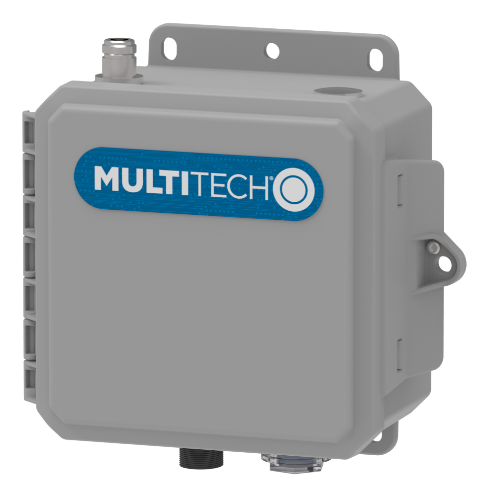
About the Conduit® IP67 Series 200 Base Station
The MultiTech Conduit® IP67 200 Series Base Station (MTCDTIP2) is a ruggedized IP67 Base Station connecting thousands of IoT assets to the cloud using the LoRaWAN® protocol. This highly scalable and certified IP67 solution is capable of resisting the harshest environmental factors including moisture, dust, wind, rain, snow and extreme heat, supporting LoRaWAN applications in virtually any environment.
Conduit IP67 Series 200 Base Station Ordering Options
| Ordering Part Number | Description | Region |
|---|---|---|
| MTCDTIP2-EN-B11EKP-D1M | Ethernet only mPower Programmable Base Station, 8-channel, 868 MHz with internal LoRa antenna. |
European Union United Kingdom United States |
| MTCDTIP2-EN-B11EKP-D1L | Ethernet only mLinux Programmable Base Station, 8-channel, 868 MHz with internal LoRa antenna. | |
| MTCDTIP2-EN-B11EKP-L1M | Ethernet only mPower Programmable Base Station, 8-channel, 868 MHz with external LoRa antenna. | |
| MTCDTIP2-EN-B11EKP-L1L | Ethernet only mLinux Programmable Base Station, 8-channel, 868 MHz with external LoRa antenna. | |
| MTCDTIP2-EN-B11UKP-L1M | Ethernet only mPower Programmable Base Station, 8-channel, 915 MHz with external LoRa antenna. | |
| MTCDTIP2-EN-B11UKP-L1L | Ethernet only mLinux Programmable Base Station, 8-channel, 915 MHz with external LoRa antenna. | |
| MTCDTIP2-L4E1-B11EKP-D1M | LTE Cat 4 mPower Programmable Base Station, 8-channel, 868 MHz with internal LoRa antenna, and internal cellular antenna. |
European Union United Kingdom |
| MTCDTIP2-L4E1-B11EKP-D1L | LTE Cat 4 mLinux Programmable Base Station, 8-channel, 868 MHz with internal LoRa antenna and internal cellular antenna. | |
| MTCDTIP2-L4E1-B11EKP-L1M | LTE Cat 4 mPower Programmable Base Station, 8-channel, 868 MHz with external LoRa antenna and internal cellular antenna. | |
| MTCDTIP2-L4E1-B11EKP-L1L | LTE Cat 4 mLinux Programmable Base Station, 8-channel, 868 MHz with external LoRa antenna and internal cellular antenna. | |
| MTCDTIP2-LNA3-B11UKP-L1M | LTE Cat 1 mPower Programmable Base Station, 8-channel, 915 MHz with external LoRa antenna and internal cellular antenna. (AT&T/Verizon) |
Canada United States |
| MTCDTIP2-LNA3-B11UKP-L1L | LTE Cat 1 mLinux Programmable Base Station, 8-channel, 915 MHz with external LoRa antenna and internal cellular antenna. (AT&T/Verizon) |
Power over Ethernet (PoE)
For information on using and troubleshooting PoE, refer to the PoE Application Note https://www.multitech.com/documents/publications/application-notes/S000678.pdf
Safety Instructions
 Warnings and Cautions
Warning and Caution symbols mean potential danger. You are in a situation that could cause bodily injury. Before working on any equipment, be aware of hazards in the installation area and be knowledgeable about electrical circuitry. Be familiar with standard practices for preventing accidents.
Les symboles d'avertissement et de mise en garde indiquent un danger potentiel. Vous vous trouvez dans une situation qui peut entraîner des blessures corporelles. Avant de travailler sur un équipement, vous devez être conscient des dangers potentiels dans la zone d'installation et connaitre les circuits électriques. Familiarisez-vous avec les pratiques normalisées de prévention des accidents.
 WARNING: Only trained and qualified
personnel should install, replace, or service this equipment. Installation must
comply with local and national electrical codes. Classification of use by: Skilled person.
WARNING: Only trained and qualified
personnel should install, replace, or service this equipment. Installation must
comply with local and national electrical codes. Classification of use by: Skilled person.
- Disconnect PoE power (Ethernet PoE port) before servicing the device.
- Do not work on the system or connect or disconnect cables during periods of lightning activity.
- This device is not designed or approved to be used in any Hazardous Locations. Do not install or operate device if area is known to be an explosive environment.
AVERTISSEMENTS: Seul un personnel formé et
qualifié doit installer, remplacer ou entretenir cet équipement. L'installation doit
être conforme aux codes électriques locaux et nationaux.- Déconnectez l'alimentation PoE (port Ethernet PoE) avant de procéder à l'entretien cet appareil.
- Ne travaillez pas sur le système et ne branchez ni débranchez les câbles pendant les périodes d'activité de la foudre.
- Cet appareil n'est ni conçu ni approuvé pour être utilisé dans des endroits dangereux. N'installez pas et ne faites pas fonctionner l'appareil si la zone est connue pour être un environnement où il y a des risques d'explosion.
 CAUTION: Power over Ethernet (PoE)
Certification does not apply or extend to voltages outside of standard PoE range.
PoE range for the MTCDTIP2 is 42.5-57 VDC.Any PoE voltages outside this range have
not been evaluated by UL or MULTITECH. The end user supplies the PoE cable.
CAUTION: Power over Ethernet (PoE)
Certification does not apply or extend to voltages outside of standard PoE range.
PoE range for the MTCDTIP2 is 42.5-57 VDC.Any PoE voltages outside this range have
not been evaluated by UL or MULTITECH. The end user supplies the PoE cable.
- Recommended PoE: 802.3at-compliant Type 2 Class 4 Power-over-Ethernet (PoE) Powered Devices (PDs) and require PoE Power Supply Equipment (PSE) that is 802.3at-compliant with minimum 25.5W output power capability.
- This is an 802.3at Type 2 device. For more information, refer to the Conduit PoE Application Note (S000678).
- Ethernet port is not designed to be connected to a public Telecommunication (PSTN) or any other connection other than IEEE 802.3-2012 power over Ethernet devices.
- Do not remove product labels.
MISES EN GARDE: La certification PoE (Power
over Ethernet) ne s'applique pas et ne s'étend pas aux tensions situées en dehors de
la plage PoE standard. La plage PoE pour le MTCDTIP2 se situe
entre 42,5 et 57 VDC. Toute tension PoE en dehors de la
plage indiquée n'a pas été évaluée par UL ou MULTITECH. L'utilisateur final fournit
le câble PoE.
- Il s'agit d'un appareil 802.3at de type 2. Pour de plus amples renseignements, reportez-vous à la note d'application PoE de Conduit (S000678).
- Le port Ethernet n'est pas conçu pour être connecté à un réseau de télécommunication public (PSTN) ou à toute autre connexion autre que les dispositifs Power over Ethernet IEEE 802.3-2012.
- Ne retirez pas les étiquettes du produit.
Installation Safety
This information is also available in the Installation Guide, in the box and available at https://www.multitech.com/brands/conduit-ip67-200. Select your model to find the correct installation guide for your device.
Warnings and Cautions
Warning and Caution symbols mean potential danger. You are in a situation that could cause bodily injury. Before working on any equipment, be aware of hazards in the installation area and be knowledgeable about electrical circuitry. Be familiar with standard practices for preventing accidents.
- When installing or replacing the unit, the ground connection must always be made first and disconnected last.
- Disconnect PoE power (Ethernet PoE port) before servicing the device.
- Do not work on the system or connect or disconnect cables during periods of lightning activity.
- This device is not designed or approved to be used in any Hazardous Locations. Do not install or operate device if area is known to be an explosive environment.
- Externally ground this equipment using a customer-supplied ground wire before applying power. Contact an electrician if you are uncertain that suitable grounding is available. Refer to Installing the Ground Wire instructions in the Installation Guide (available at https://www.multitech.com/brands/conduit-ip67-200). All wall mounting installations are subject to the acceptance of local jurisdiction.
Operation Safety
ATTENTION: Lisez toutes les instructions et consignes de sécurité avant d'installer ou d'utiliser cet appareil.
- Follow all local laws, regulations, and rules for operating a wireless device.
- Use the device security features to block unauthorized use and theft.
- Unless otherwise noted, antennas are not approved for outdoor use. Do not extend any antenna outside of any building, dwelling, or campus.
- Do not attempt to disassemble the device. There are no user-serviceable parts inside.
- Do not misuse the device. Follow instructions on proper operation and only use as intended. Misuse could make the device inoperable, damage the device or other equipment, or harm users.
- Do not apply excessive pressure or place unnecessary weight on the device. This could result in damage to the device or harm to users.
- Do not use this device in explosive or hazardous environments unless the model is specifically approved for such use. The device may cause sparks. Sparks in explosive areas could cause an explosion or fire that may result in property damage, severe injury, or death.
- Do not expose the device to any extreme environment where the temperature or humidity is high. Such exposure could result in damage to the device or cause a fire. See the device specifications for recommended operating temperature and humidity.
- Do not expose the device to water, rain, or other liquids. It is not waterproof. Exposure to liquids could result in damage to the device.
- Using accessories, such as antennas, that MultiTech has not authorized or that are not compliant with the device accessory specifications may invalidate the warranty.
If the device is not working properly, contact MultiTech technical support.
Lithium Battery
- A lithium battery (3V, coin cell, CR1632) located within the product provides backup power for the timekeeping. If the device is left powered off, the battery lasts approximately 90 days.
- When this battery starts to weaken, the date and time may be incorrect.
- Battery is not user replaceable. If the battery fails, the device must be sent back to MultiTech Systems for battery replacement.
- Lithium cells and batteries are subject to the Provisions for International Transportation. Multi-Tech Systems, Inc. confirms that the Lithium batteries used in the MultiTech product(s) referenced in this manual comply with Special Provision 188 of the UN Model Regulations, Special Provision A45 of the ICAO-TI/IATA-DGR (Air), Special Provision 310 of the IMDG Code, and Special Provision 188 of the ADR and RID (Road and Rail Europe).
ATTENTION: Risque d'explosion si vous remplacez la batterie par un modèle incompatible. Jetez les piles usagées selon les instructions.
Notice regarding Compliance with FCC, EU, and Industry Canada Requirements for RF Exposure
The antenna intended for use with this unit meets the requirements for mobile operating configurations and for fixed mounted operations, as defined in 2.1091 of the FCC rules for satisfying RF exposure compliance. This device also meets the European RF exposure requirements of EN 62311. If an alternate antenna is used, consult user documentation for required antenna specifications.
Compliance of the device with the FCC, EU, and IC rules regarding RF Exposure was established and is given with the maximum antenna gain as specified above for a minimum distance of 35 cm between the devices radiating structures (the antenna) and the body of users. Qualification for distances closer than 35 cm (portable operation) would require re-certification.
Wireless devices could generate radiation. Other nearby electronic devices, like microwave ovens, may also generate additional radiation to the user causing a higher level of RF exposure.
Radio Frequency (RF) Safety
Due to the possibility of radio frequency (RF) interference, it is important that you follow any special regulations regarding the use of radio equipment. Follow the safety advice given below.
- Operating your device close to other electronic equipment may cause interference if the equipment is inadequately protected. Observe any warning signs and manufacturers’ recommendations.
- Different industries and businesses restrict the use of cellular devices. Respect restrictions on the use of radio equipment in fuel depots, chemical plants, or where blasting operations are in process. Follow restrictions for any environment where you operate the device.
- Do not place the antenna outdoors.
- Turn off your wireless device when in an aircraft. Using portable electronic devices in an aircraft may endanger aircraft operation, disrupt the cellular network, and may be illegal. Failing to observe this restriction may lead to suspension or denial of cellular services to the offender, legal action, or both.
- Turn off your wireless device when around gasoline or diesel‑fuel pumps and before filling your vehicle with fuel.
- Turn off your wireless device in hospitals and any other place where medical equipment may be in use.
Sécurité relative aux appareils à radiofréquence (RF)
À cause du risque d'interférences de radiofréquence (RF), il est important de respecter toutes les réglementations spéciales relatives aux équipements radio. Suivez les conseils de sécurité ci-dessous.
- Utiliser l'appareil à proximité d'autres équipements électroniques peut causer des interférences si les équipements ne sont pas bien protégés. Respectez tous les panneaux d'avertissement et les recommandations du fabricant.
- Certains secteurs industriels et certaines entreprises limitent l'utilisation des appareils cellulaires. Respectez ces restrictions relatives aux équipements radio dans les dépôts de carburant, dans les usines de produits chimiques, ou dans les zones où des dynamitages sont en cours. Suivez les restrictions relatives à chaque type d'environnement où vous utiliserez l'appareil.
- Ne placez pas l'antenne en extérieur.
- Éteignez votre appareil sans fil dans les avions. L'utilisation d'appareils électroniques portables en avion est illégale: elle peut fortement perturber le fonctionnement de l'appareil et désactiver le réseau cellulaires. S'il ne respecte pas cette consigne, le responsable peut voir son accès aux services cellulaires suspendu ou interdit, peut être poursuivi en justice, ou les deux.
- Éteignez votre appareil sans fil à proximité des pompes à essence ou de diesel avant de remplir le réservoir de votre véhicule de carburant.
- Éteignez votre appareil sans fil dans les hôpitaux ou dans toutes les zones où des appareils médicaux sont susceptibles d'être utilisés.
Interference with Pacemakers and Other Medical Devices
Radio frequency energy (RF) from cellular devices can interact with some electronic devices. This is electromagnetic interference (EMI). The FDA helped develop a detailed test method to measure EMI of implanted cardiac pacemakers and defibrillators from cellular devices. This test method is part of the Association for the Advancement of Medical Instrumentation (AAMI) standard. This standard allows manufacturers to ensure that cardiac pacemakers and defibrillators are safe from cellular device EMI.
The FDA continues to monitor cellular devices for interactions with other medical devices. If harmful interference occurs, the FDA will assess the interference and work to resolve the problem.
Precautions for Pacemaker Wearers
If EMI occurs, it could affect a pacemaker in one of three ways:
- Stop the pacemaker from delivering the stimulating pulses that regulate the heart's rhythm.
- Cause the pacemaker to deliver pulses irregularly.
- Cause the pacemaker to ignore the heart’s own rhythm and deliver pulses at a fixed rate.
Based on current research, cellular devices do not pose a significant health problem for most pacemaker wearers. However, people with pacemakers may want to take simple precautions to be sure that their device doesn't cause a problem.
- Keep the device on the opposite side of the body from the pacemaker to add extra distance between the pacemaker and the device.
- Avoid placing a turned-on device next to the pacemaker (for example, don’t carry the device in a shirt or jacket pocket directly over the pacemaker).
Vehicle Safety
When using your device in a vehicle:
- Do not use this device while driving.
- Respect local regulations on the use of cellular devices in vehicles.
- If incorrectly installed in a vehicle, operating the wireless device could interfere with the vehicle’s electronics. To avoid such problems, use qualified personnel to install the device. The installer should verify that the vehicle electronics are protected from interference.
- Using an alert device to operate a vehicle’s lights or horn is not permitted on public roads.
- UL evaluated this device for use in ordinary locations only. UL did not evaluate this device for installation in a vehicle or other outdoor locations. UL certification does not apply or extend to use in vehicles or outdoor applications.
Safety Statements
The following are translations of key cautions and warnings from the Conduit IP67 Base Station 200 Series MTCDTIP2 Installation Guide.
English
CAUTION: Read installation instructions and safety information before starting Base Station installation. Do not connect power until directed to do so.
WARNING: If you connected power to the device, disconnect it before continuing.
Bulgarian
ВНИМАНИЕ: Прочетете инструкциите за монтаж и информацията за безопасност, преди да започнете монтаж на базовата станция. Не включвайте захранването, преди да е упоменато.
ПРЕДУПРЕЖДЕНИЕ: Ако вече сте включили захранването в устройството, изключете го, преди да продължите.
Chinese

Czech
VAROVÁNÍ: Před zahájením instalace základní stanice si přečtěte pokyny k instalaci a bezpečnostní informace. Nepřipojujte napájení, dokud k tomu nebudete vyzváni.
VÝSTRAHA: Pokud jste k zařízení připojili napájení, před pokračováním ho odpojte.
Danish
FORSIGTIG: Læs installationsinstruktionerne og sikkerhedsinformationerne, inden du begynder på installation af basisstationen. Tilslut ikke strømmen, før du bliver bedt om det.
ADVARSEL! Hvis du sluttede enheden til strømmen, så frakobl den, inden du fortsætter.
Dutch
LET OP: Lees de installatie-instructies en veiligheidsinformatie voordat u aan de installatie van het Base Station begint. Sluit de stroom pas aan als dit wordt aangegeven.
WAARSCHUWING! Als u het apparaat op de stroomtoevoer hebt aangesloten, koppel deze dan los voordat u verder gaat.
Estonian
ETTEVAATUST: Enne alusjaama paigaldust, tutvuge paigaldusjuhiste ja ohutusalase teabega. Ärge ühendage vooluvõrku enne, kui seda on selgesõnaliselt soovitatud.
HOIATUS: Kui ühendasite seadme vooluvõrguga, siis võtke pistik enne jätkamist vooluvõrgust välja.
Flemish
OPGELET: Lees de installatie-instructies en veiligheidsinformatie voor u de installatie van het Basisstation start. U mag de stroom pas aansluiten wanneer u de instructie krijgt om dit te doen.
WAARSCHUWING: Als u de stroom hebt aangesloten op het apparaat moet u hem loskoppelen voor u doorgaat.
French
ATTENTION: Lisez les instructions d'installation et les consignes de sécurité avant de commencer l'installation de la station de base. Ne faîtes aucune connexion avant d'avoir reçu des instructions à cet effet.
AVERTISSEMENT: Si vous avez déjà effectué une connexion à l'appareil, débranchez-la avant de continuer.
German
ACHTUNG: Vor Installation der Basisstation die Installationsanweisungen und Sicherheitshinweise lesen. Die Stromversorgung erst nach Aufforderung anschließen.
WARNUNG: Vor dem Fortfahren die Stromversorgung trennen, falls sie an das Gerät angeschlossen wurde.
Hungarian
VIGYÁZAT: A bázisállomás telepítésének megkezdése előtt olvassa el a telepítési utasításokat és a biztonsági információkat. Ne helyezze áram alá, amíg erre utasítást nem kap.
FIGYELEM: Ha az eszközt már áram alá helyezte, a folytatás előtt csatlakoztassa le.
Italian
ATTENZIONE: leggere le istruzioni per l'installazione e le informazioni di sicurezza prima di iniziare l'installazione della stazione di base. Non collegare l'alimentazione fino a quando non viene richiesto.
AVVERTENZA: se il dispositivo è stato collegato alla corrente, scollegarlo prima di continuare.
Korean

Latvian
UZMANĪBU: Pirms uzstādīt bāzes staciju, izlasiet uzstādīšanas norādījumus un drošības informāciju. Nepieslēdziet barošanu, kamēr nav sniegts atbilstošs norādījums.
BRĪDINĀJUMS. Ja ierīcei ir pieslēgta barošana, pirms turpināt darbu, atvienojiet to.
Lithuanian
ATSARGIAI: Prieš pradėdami montuoti bazinę stotį, perskaitykite montavimo instrukciją ir saugos informaciją. Elektros maitinimą junkite tik tada, kai gausite tokį nurodymą.
ĮSPĖJIMAS: Jeigu įrenginys buvo prijungtas prie elektros maitinimo, atjunkite jį prieš tęsdami darbą.
Norwegian
FORSIKTIG: Les installasjonsinstruksjonene og sikkerhetsinformasjonen før du starter installasjonen av basestasjonen. Ikke koble til strømmen før du blir bedt om det.
ADVARSEL: Hvis du koblet strøm til apparatet, koble den fra før du fortsetter.
Polish
PRZESTROGA: Przed rozpoczęciem montażu stacji bazowej należy zapoznać się z instrukcją montażu oraz informacjami dotyczącymi bezpieczeństwa. Nie należy podłączać zasilania bez wyraźnego polecenia.
UWAGA: Jeżeli zasilanie zostało podłączone do urządzenia, należy je odłączyć przed kontynuowaniem prac.
Romanian
ATENȚIE: Înainte de a începe instalarea stației de bază citiți instrucțiunile de instalare și informațiile referitoare la siguranță. Nu conectați la curent până când nu vi se indică să faceți acest lucru.
AVERTISMENT: Dacă ați conectat dispozitivul la curent, deconectați-l înainte de a continua.
Russian
ВНИМАНИЕ: Перед началом установки базовой станции прочтите инструкции по установке и информацию по технике безопасности. Не подключайте питание, пока не получите соответствующие указания.
ПРЕДУПРЕЖДЕНИЕ. Если вы подключили питание к устройству, отключите его, прежде чем продолжить.
Spanish
PRECAUCIÓN: Lea las instrucciones de instalación y la información de seguridad antes de instalar la estación base. No conecte la alimentación eléctrica del dispositivo hasta que no se le indique.
ADVERTENCIA: Si ha conectado la alimentación eléctrica del dispositivo, desconéctela antes de continuar.
Swedish
FÖRSIKTIG! Läs installationsanvisningarna och säkerhetsinformationen innan du påbörjar installationen av basstationen. Koppla inte in strömmen förrän du blir anvisad att göra så.
VARNING! Om du har kopplat in strömmen till enheten ska du koppla ut den innan du fortsätter.
Specifications
LNA3 Base Station Specifications
| Category | Description |
|---|---|
| General | |
| Standards | LoRaWAN 1.0.2 specifications |
| LTE 3GPP Release 9 (-LNA3 models only) | |
| HSPA+ (-LNA3 models only) | |
| RAM | 256MB |
| Flash | 256MB |
| Radio Frequency | |
| ISM Band | NA915, AU915, and AS23 |
| 4G/LTE | -LNA3 models only 1900 (B2) / AWS 1700 (B4) / 850 (B5) / 700 (B12/13) |
| 3G | -LNA3 models only 1900 (B2) / 850 (B5) |
| Physical Description | |
| Weight | 2.09 lbs (0.95 kg) |
| Dimensions | Refer to Mechanical Drawings for Dimensions. |
| Chassis Type | IP67-Rated composite |
| Environment | |
| Operating Temperature1 | -40° C to +70° C |
| Storage Temperature | -40° C to +85° C |
| Humidity | 20%-90% RH, non-condensing |
| Power Requirements | |
| PoE Input Power | 42.5 to 57 VDC with Ethernet speed 10/100 |
| PoE Standard: | IEEE 802.3at |
| Minimum Watts | 15W (Minimum watts required to run the device) |
| Certifications and Compliance | |
| Outdoor Certification/IP Outdoor Protected Class | UL/CSA 60950-22 & IP67 |
| EMC and Radio Compliance | FCC Part 15B (Class A) |
| FCC Part 15C | |
| FCC Part 22 24, 27 | |
| ICES-003 Class A | |
| ISED. RSS-247 Issue 2 (Canada) | |
| Safety Compliance | UL 62368-1 2nd Ed |
| cUL 62368-1 2nd Ed | |
| UL 60950-1 | |
| cUL 60950-1 | |
1Product has been tested to +70° C excluding PoE supply. PoE supply temperature rating and operation depend on the environment where the PoE supply is located. The selected PoE supply must be designed and certified to limit power source (LPS) and meet MTCDTIP2 power ratings.
L4E1 Base Station Specifications
| Category | Description |
|---|---|
| General | |
| Standards | LoRaWAN 1.0.2 specifications |
| LTE FDD Cat 4, 3GPP release compliant (-L4E1 models only) | |
| HSPA+ with GPRS fallback (-L4E1 models only) | |
| RAM | 256MB |
| Flash | 256MB |
| Radio Frequency | |
| ISM Band | 868 MHz ISM band for Europe |
| 4G/LTE | 4G: 1800 (B3), 2600 (B7), 800 (B20), 2100 (B1), 900 (B8), 700 (B28A) |
| 3G | 3G: 2000 (B1), 1800 (B3), 900 (B8) |
| 2G | 2G: 1800 (B3), 900 (B8) |
| Physical Description | |
| Weight | 0.95 kg |
| Dimensions | Refer to Mechanical Drawings for Dimensions. |
| Chassis Type | IP67-Rated composite |
| Environment | |
| Operating Temperature1 | -40° C to +70° C |
| Storage Temperature | -40° C to +85° C |
| Humidity | 20%-90% RH, non-condensing |
| Altitude During Operation | 5000 meters maximum |
| PoE and Power Requirements | |
| PoE Input Power | 42.5 to 57 VDC |
| PoE Standard: | IEEE 802.3at |
| Ethernet Speed | 10/100 Mbps |
| Minimum Watts | 15W (Minimum watts required to run the device) |
| Certifications and Compliance | |
| Outdoor Certification/IP Outdoor Protected Class | IP67 & IEC 60950-222 |
| EMC and Radio Compliance | EN 55032 Class A |
| EN 301 489-3 V2.1.1 for RED | |
| EN 301 489-1 V2.2.0 for RED | |
| EN 301 489-52 V1.1.0 Harmonized standard for cellular RED | |
| EN 300 220-1 V3.1.1 | |
| EN 300 220-2 V3.1.1 | |
| EN 300 328 V2.1.1 | |
| EN 301 489-19 | |
| EN 301 511 V9.0.2 | |
| EN 301 893 V2.1.1 | |
| EN 301 908-1 V11.1.1 | |
| EN 301 902-2 V11.1.1 | |
| EN 301 908-13 V11.1.1 | |
| EN 62311-2008 | |
| Safety Compliance | IEC 62368-1 2nd Ed |
| IEC 62368-1 | |
1Product has been tested to +70° C excluding PoE supply. PoE supply temperature rating and operation depend on the environment where the PoE supply is located. The selected PoE supply must be designed and certified to limit power source (LPS) and meet MTCDTIP2 power ratings.
Labels
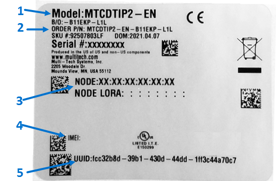
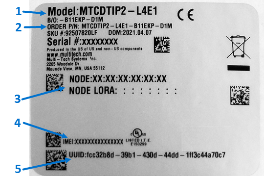
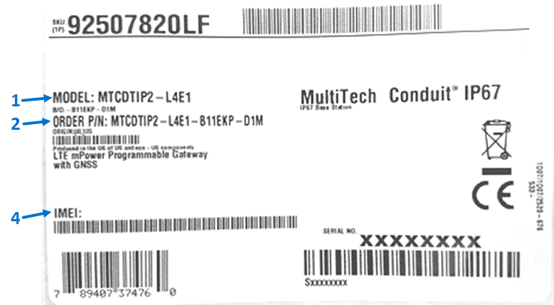
This device complies with part 15 of the FCC Rules. Operation is subject to the following two conditions: (1) This device may not cause harmful interference, and (2) this device must accept any interference received, including interference that may cause undesired operation.
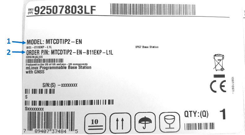
The label shown is not the actual size.
- 1 - MultiTech Model Identification.
- 2 - MultiTech Ordering Part Number.
- 3 - Device Node Number
- 4 - IMEI Number
- 5 - UUID
Label images are not actual size.
| Device Label Examples: | Package Label Examples: |
 |
 |
 |
 |
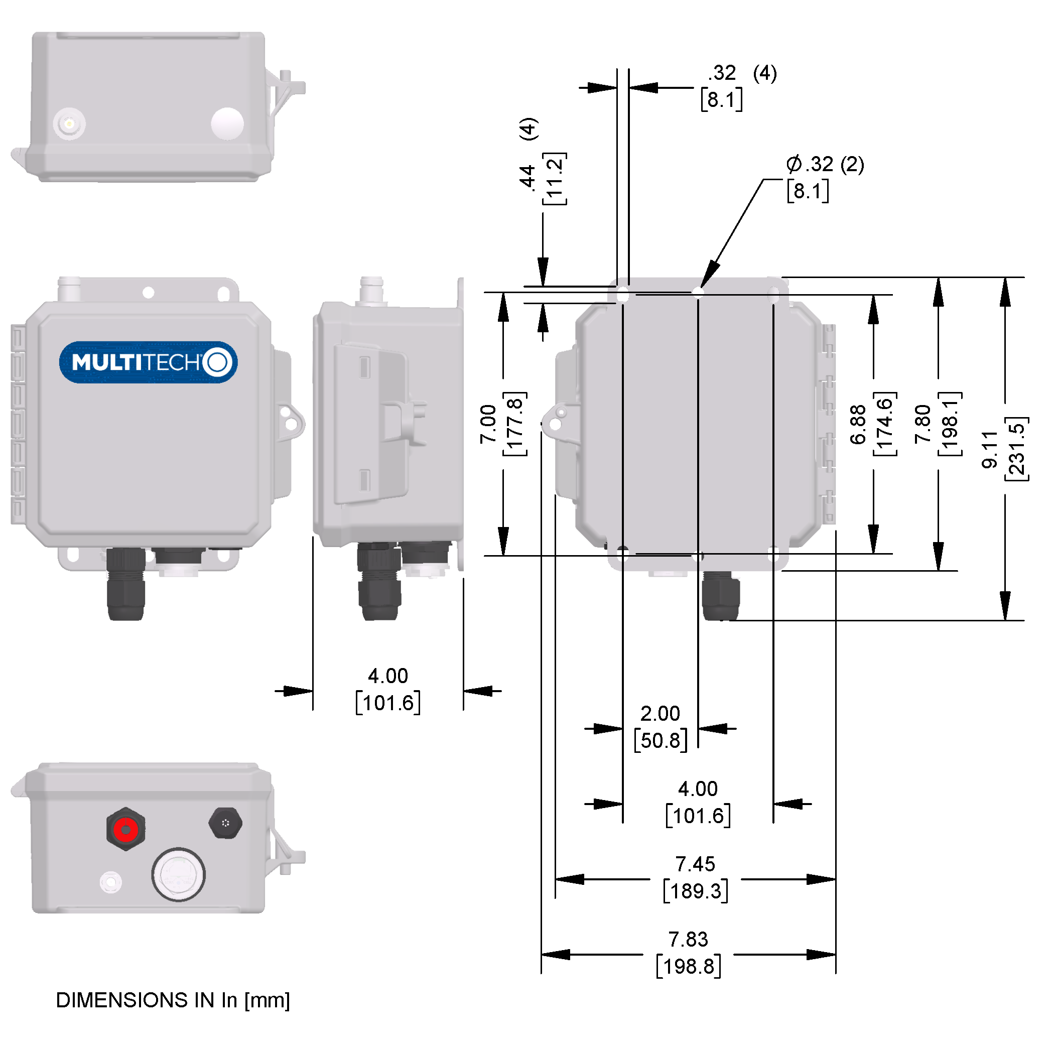
Dimensions
LEDs and Connectors
External Antenna Models

| # | Connector | Description |
|---|---|---|
| 1 | Ethernet Port | Ethernet port with IP67 rated cable gland (supports cable diameter between 5.5 and 7 mm). |
| 2 | Grounding Lug | Connector for ground wire. |
| 3 | SIM Slot and LEDs | Under a plastic cover, for all models, LEDs. For cellular models, a SIM holder. (See Cellular models image under LEDs for more detail.) |
| 4 | Vent Valve | Protective breathable vent plug. |
| 5 | LoRa | Connector for LoRa antenna. |
Internal Antenna Models

| # | Connector | Description |
|---|---|---|
| 1 | Ethernet Port | Ethernet port with IP67 rated cable gland. |
| 2 | Grounding Stud | Connector for ground wire. |
| 3 | SIM Slot and LEDs | Under a plastic cover. For all models, LEDs. For cellular models, a SIM holder (3FF micro SIM). |
LEDs
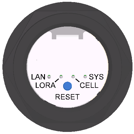 LoRa only models |
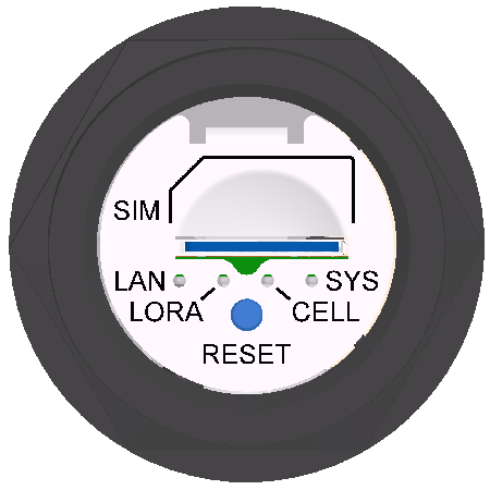 Cellular models |
| Label | Description |
|---|---|
| LAN | Lights when Ethernet is connected. Blinks when there is data. |
| LORA | Lights when LoRa software is active. |
| SYS | Blinks when operating system is fully loaded. |
| CELL | Cellular models only. Lights when there is power to the radio. Blinks when the SIM is registered with the carrier. |
LNA3 Base Station Cellular Power Measurements
- Multi-Tech Systems, Inc. recommends that you incorporate a 10% buffer into the power source when determining product load.
- Maximum Power: The continuous current during maximum data rate with the radio transmitter/LoRa at maximum power.
- Tx Pulse: The average peak current during HSDPA/LTE connection with LoRa at Max power.
- Inrush Charge: The total inrush charge at power on.
| Voltage | Power Down Mode via Radio Command | Live Connection Idle (No Data) | Average Measured Current at Max Power | TS Pulse Average Peak Current for HSDPA/ LTE | Total Inrush Charge measured in MilliCoulombs | Total Inrush Charge DURATION during Powerup (INRUSH Duration0 |
|---|---|---|---|---|---|---|
| LTE BAND 5 (836.5 Mhz) | ||||||
| 38VDC POE | 47 mA | 59 mA | 171 mA | 328 mA | 1.52 mC | 32.8 mS |
| 56VDC POE | 36 mA | 49 mA | 125 mA | 252 mA | 1.21 mC | 21.6 mS |
| WCDMA Band 2 1854 MHz | ||||||
| 38VDC POE | 46 mA | 52 mA | 210 mA | 368 mA | 1.52 mC | 32.8 ms |
| 56VDC POE | 36 mA | 47 mA | 151 mA | 220 mA | 1.21 mC | 21.6 mS |
L4E1 Base Station Cellular Power Measurements
- Multi-Tech Systems, Inc. recommends that you incorporate a 10% buffer into the power source when determining product load.
- Maximum Power: The continuous current during maximum data rate with the radio transmitter/LoRa at maximum power.
- Tx Pulse: The average peak current during HSDPA/LTE connection with LoRa at Max power.
- Inrush Charge: The total inrush charge at power on.
| Voltage | Power Down Mode via Radio Command | Cellular Call Box Connection (No Data) | Average Measured Current at Max Power | TS Pulse Average Peak Current for HSDPA/ LTE | Total Inrush Charge measured in MilliCoulombs | Total Inrush Charge DURATION during Powerup (INRUSH Duration) |
|---|---|---|---|---|---|---|
| LTE BAND 7 (2535 Mhz) | ||||||
| 37VDC POE | 51 mA | 53 mA | 212 mA | 388 mA | 1.16 mC | 8.98 mS |
| 57VDC POE | 41 mA | 42 mA | 151 mA | 276 mA | 1.06 mC | 8.0 mS |
| WCDMA Band 1 (1922.4 MHz) | ||||||
| 37VDC POE | 47 mA | 51 mA | 218 mA | 380 mA | 1.16 mC | 8.98 mS |
| 57VDC POE | 41 mA | 41 mA | 153 mA | 272 mA | 1.06 mC | 8.0 mS |
| EGSM (900 MHz) | ||||||
| 37VDC POE | 46 mA | 52 mA | 158 mA | 395 mA | 1.16 mC | 8.98 mS |
| 57VDC POE | 36 mA | 41 mA | 110 mA | 270 mA | 1.06 mC | 8.0 mS |
Ethernet Models
- Multi-Tech Systems, Inc. recommends that you incorporate a 10% buffer into the power source when determining product load.
- Maximum Power: The continuous current during maximum data rate with the LoRa at maximum power setting.
- Tx Pulse: The average peak current during LoRa transmission.
- Inrush Charge: The total inrush charge at power on.
| Voltage | Idle Measure | Average Measured Current at Max Power | TS Pulse Average Peak Current for HSDPA/ LTE | Total Inrush Charge measured in MilliCoulombs | Total Inrush Charge DURATION during Powerup (INRUSH Duration0 |
|---|---|---|---|---|---|
| 37VDC POE | 49 mA | 96 mA | 260 mA | 0.818 mC | 7.61 mS |
| 57VDC POE | 34 mA | 71 mA | 140 mA | 0.962 mC | 7.70 mS |
Antenna Information
Antenna
Depending on the model, your Base Station ships with one of the following antennas.
Due to FCC 15.203 regulations, the MTCDTIP2 requires installation by a professional, to insure the integrity of the radio transmission system. The authority to operate the LoRa transmitter will be void if using antennas other than the ones listed in the following table. Contact MultiTech for additional antenna information.
| Manufacturer | Model | Description |
|---|---|---|
| L-Com | HGV-906U | 6dBi Gain IP67 Lora Antenna |
| Pulse | RO8063/21704NM | 3dBi Gain IP67 Lora Antenna |
ISED Antenna Approval
This radio transmitter 125A-0062 has been approved by Innovation, Science and Economic Development Canada to operate with the antenna types listed below, with the maximum permissible gain indicated. Antenna types not included in this list that have a gain greater than the maximum gain indicated for any type listed are strictly prohibited for use with this device.
Le présent émetteur radio 125A-0062 a été approuvé par Innovation, Sciences et Développement économique Canada pour fonctionner avec les types d'antenne énumérés ci‑dessous et ayant un gain admissible maximal. Les types d'antenne non inclus dans cette liste, et dont le gain est supérieur au gain maximal indiqué pour tout type figurant sur la liste, sont strictement interdits pour l'exploitation de l'émetteur.
Pulse Omnidirectional Antenna
| Manufacturer: | Pulse |
| Description: | Omnidirectional antenna 806-960/1710-2170 MHz radome |
| Model Number: | RO8063/21704NM |

Antenna Specifications
| Category | Description |
|---|---|
| Frequency Range | 806-960 MHz |
| 1710-2170 MHz | |
| VSWR | 2.5:1 Max |
| Gain, Maximum | 3.0 dBi ± 1 dB at 806-960 MHz |
| 4.0 dBi ± 1 dB at at 1710-2170 MHz | |
| Polarization | Vertical |
| Impedance | 50 Ω |
| Radiation Pattern | 3 dB Beamwidth |
| Horizontal Plane | Omni |
| Vertical Plane - 806-960 | 53° Avg |
| Vertical Plane – 1710-2170 | 39° Avg |
| Dimensions | 15.28 inches (388.5 mm) x 1.45 inches (36.9 mm) |
L-com Omnidirectional Antenna
| Manufacturer: | L-com |
| Description: | Hyperlink Wireless 800/900 MHz 6dBi High Performance Omnidirectional antenna |
| Model Number: | HGV-906U |
Antenna Specifications
| Category | Description |
|---|---|
| Frequency Range | 824-960 MHz |
| VSWR | < 1.5:1 Avg |
| Gain, Maximum | 6.0 dBi ± 1 dB |
| Polarization | Vertical |
| Impedance | 50 Ω |
| Max. Input Power | 100 Watts |
| Horizontal Plane | 360° |
| Vertical Plane | 30° |
| Dimensions | 23.6 inches (599.44 mm) x 1.3 inches (50.8 mm) |
| Rated Wind Velocity | 108 MPH |
Installation
Connector Locations
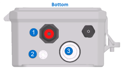
| # | Connector | Description |
|---|---|---|
| 1 | Ethernet Port | Ethernet port with IP67 rated cable gland. |
| 2 | Grounding Lug | Connector for ground wire. |
| 3 | SIM Slot, Reset, LEDs | Under a plastic cover, for all models, LEDs and reset button. For cellular models, a SIM holder. See hardware guide for LED details |
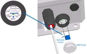
Install a Micro SIM Card
To install a SIM card:
- Remove the SIM cover.
- Gently push the micro SIM card into the holder with the cut corner to the left
and the SIM contacts facing down as shown.

- Reattach the plastic cover and tighten to 10.5 lbf.in (12 kgf.cm).
Install a Ground Wire
Proper grounding of the enclosure is required to ensure safety and prevent equipment damage. The device enclosure has a grounding lug on the bottom (#2 in Connector Locations). Connecting the grounding lug to an earth ground is required. Refer to the National Electric Code or your local codes for additional information or contact a licensed electrician for assistance in grounding an installation.
Ground wire (not provided) must be suitable for outdoor location and meet a minimum wire gauge of 14 AWG or larger. Ground wire terminal (not provided) must be closed loop (ring type, see image) and corrosive free in design.

- Remove the nut on the grounding lug.
- Put the loop terminal on the grounding lug.
- Replace the nut and tighten to 10 in-lbs (11.5 kg.cm) or firmly by hand.
- Run the ground wire to a safe earth ground location where the energy can be dispersed.
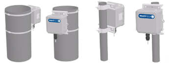
Mount to a Pole
You will need a mounting kit. MultiTech has mounting kits for a variety of pole sizes. The pole should be made of a corrosive free material with UV protection and able to support four times the weight of the MTCDTIP2 with accessories attached.
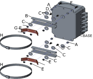
| Item | Description | Quantity |
|---|---|---|
| A | Spacer, 1/4" | 4 |
| B | Strut Rails | 2 |
| C | Fender Washer, 1/4" | 12 |
| D | Pan Head Screws, 1/4-20 x 1/2" | 4 |
| E | Nylon Nut, 1/4 -20 | 8 |
| F | Pan Head Screws, 1/4-20 x 7/8" | 4 |
| G | Band Clamp Bracket | 2 |
| H | Hose Clamp | 2 |
- Attach band clamp brackets (G) through slots in strut rails (B) and secure with pan head screws (D), fender washers (C), and nylon nuts (E) (x4).Torque to 32 in-lbs (36.8 kg-cm) max.
- Install pan head screws (F) through slots in enclosure base (x4). Align spacers (A) and fender washers (C) over ⅞ ” screw length sticking through at the rear of the MTCDTIP2. Attach strut rail sub assembly to MTCDTIP2 securing with fender washers (C) and nylon nuts (E). Torque to 32 in-lbs (36.8 kg-cm) max.
- Feed hose clamp (H) through slots in band clamp (G) (x2).
- Wrap hose clamps around pole and tighten.
Mount on a Wall
The location should be able to support four times the weight of the MTCDTIP2 with accessories attached.
To mount the device on a wall:
- Use ¼ inch x 1¼ inch (minimum length) screws in the mounting holes tabs on the chassis. Use with wall anchors if necessary.
Connect the Ethernet Cable
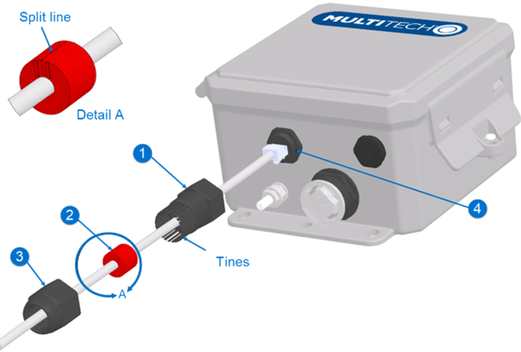
| Item | Connector |
|---|---|
| 1 | Cable Gland Body |
| 2 | Cable Gland Seal |
| 3 | Cable Gland Nut |
| 4 | Ethernet Port Threads |
To connect the Ethernet cable to the device:
- Slide the cable gland nut and the cable gland body onto the cable and plug the cable into the Ethernet port as shown.
- Install the cable gland body and then tighten to a torque specification of 10 in-lbs (11.5 kg.cm) or firmly by hand.
- Pull the cable gland seal apart at the split line and install it onto the cable as shown.
- Push the cable gland seal into the cable gland body on the end with the tines.
- Install the cable gland nut onto the cable gland body threads and then hold the cable gland body while tightening the cable gland nut to a torque specification of 10 in-lbs (11.5 kg.cm) or firmly by hand.
Operation
Reset Button
- A slim screwdriver (1 or 2mm), paperclip, or similar thin object that can fit into the reset hole.
The following is the default condition for the RESET button on the device. You can program a change to the behavior of the button if needed. To reset the device:
-
Remove the clear plastic cap.

Disposal
Instructions for Disposal of WEEE by Users in the European Union
The symbol shown below is on the product or on its packaging, which indicates that this product must not be disposed of with other waste. Instead, it is the user's responsibility to dispose of their waste equipment by handing it over to a designated collection point for the recycling of waste electrical and electronic equipment. The separate collection and recycling of your waste equipment at the time of disposal will help to conserve natural resources and ensure that it is recycled in a manner that protects human health and the environment. For more information about where you can drop off your waste equipment for recycling, contact your local city office, your household waste disposal service or where you purchased the product.
|
July, 2005 |
 |
Regulatory Information
FCC Notices
47 CFR Part 15 Regulation Class A Devices
This equipment has been tested and found to comply with the limits for a Class A digital device, pursuant to part 15 of the FCC Rules. These limits are designed to provide reasonable protection against harmful interference when the equipment is operated in a commercial environment. This equipment generates, uses, and can radiate radio frequency energy and, if not installed and used in accordance with the instruction manual, may cause harmful interference to radio communications. Operation of this equipment in a residential area is likely to cause harmful interference in which case the user will be required to correct the interference at his own expense.
- Reorient or relocate the receiving antenna.
- Increase the separation between the equipment and receiver.
- Plug the equipment into an outlet on a circuit different from that to which the receiver is connected.
- Consult the dealer or an experienced radio/TV technician for help.
FCC Interference Notice
- This device may not cause harmful interference, and
- This device must accept any interference received, including interference that may cause undesired operation.
FCC Grant Information
| FCC Identifier: | RI7LE910NA |
| Equipment Class: | Part 15 Class B Computing Device Peripheral |
| Notes: | LTE/3G/2G Module |
| Modular Type: | Single Modular |
| FCC Rule Parts: | 15B |
| FCC Identifier: | RI7LE910NA |
| Equipment Class: | PCS Licensed Transmitter |
| Notes: | LTE/3G/2G Module |
| Modular Type: | Single Modular |
| FCC Rule Parts: | 22H, 24E, 27, |
| Rule Parts | Frequency Range | Output Wats | Frequency Tolerance | Emission Designator |
|---|---|---|---|---|
| 22H | 824.2 - 848.2 | 1.64059 | 1.0 PM | 248KGXW |
| 22H | 824.2 - 848.2 | 0.42554 | 1.0 PM | 248KG7W |
| 24E | 1850.2 - 1909.8 | 0.93325 | 1.0 PM | 253KGXW |
| 24E | 1850.2 - 1909.8 | 0.23439 | 1.0 PM | 246KG7W |
| 22H | 826.4 846.6 | 0.21727 | 1.0 PM | 4M16G9W |
| 22H | 826.4 - 846.6 | 0.20845 | 1.0 PM | 4M18G9W |
| 22H | 826.4 - 846.6 | 0.20989 | 1.0 PM | 4M17G9W |
| 24E | 1852.4 - 1907.6 | 0.22336 | 1.0 PM | 4M15G9W |
| 24E | 1852.4 - 1907.6 | 0.19231 | 1.0 PM | 4M17G9W |
| 24E | 1852.4 - 1907.6 | 0.18155 | 1.0 PM | 4M17G9W |
| 27 | 706.5 - 713.5 | 0.18408 | 1.0 PM | 4M52G7W |
| 27 | 706.5 - 713.5 | 0.16406 | 1.0 PM | 4M52D7W |
| 27 | 709.0 - 711.0 | 0.18967 | 1.0 PM | 8M98G7W |
| 27 | 709.0 - 711.0 | 0.17458 | 1.0 PM | 9M01D7W |
| 22H | 826.5 - 846.5 | 0.20559 | 1.0 PM | 4M51G7W |
| 22H | 826.5 - 846.5 | 0.16904 | 1.0 PM | 4M50D7W |
| 22H | 829.0 - 844.0 | 0.19409 | 1.0 PM | 9M00G7W |
| 22H | 829.0 - 844.0 | 0.16331 | 1.0 PM | 9M00D7W |
| 27 | 1712.5 - 1752.5 | 0.17378 | 1.0 PM | 4M51G7W |
| 27 | 1712.5 - 1752.5 | 0.17906 | 1.0 PM | 4M51D7W |
| 27 | 1715.0 - 1750.0 | 0.1803 | 1.0 PM | 9M01G7W |
| 27 | 1715.0 - 1750.0 | 0.1766 | 1.0 PM | 8M89D7W |
| 27 | 1720.0 - 1745.0 | 0.18113 | 1.0 PM | 17M9G7W |
| 27 | 1720.0 - 1745.0 | 0.19454 | 1.0 PM | 18M0D7W |
| 24E | 1852.5 - 1907.5 | 0.19815 | 1.0 PM | 4M50G7W |
| 24E | 1852.5 - 1907.5 | 0.18793 | 1.0 PM | 4M51D7W |
| 24E | 1855.0 - 1905.0 | 0.18155 | 1.0 PM | 9M01G7W |
| 24E | 1855.0 - 1905.0 | 0.18323 | 1.0 PM | 8M97D7W |
| 24E | 1860.0 - 1900.0 | 0.1803 | 1.0 PM | 17M9G7W |
| 24E | 1860.0 - 1900.0 | 0.17579 | 1.0 PM | 17M9D7W |
Single Modular Approval. Power output listed is conducted. This device is approved for mobile and fixed use with respect to RF exposure compliance, and may only be marketed to OEM installers. The antenna(s) used for this transmitter, as described in this filing, must be installed to provide a separation distance of at least 20 cm from all persons and must not be co-located or operate in conjunction with any other antenna or transmitter, except in accordance with FCC multi-transmitter product procedures. Installers and end-users must be provided with operating conditions for satisfying RF exposure compliance. Maximum permitted antenna gain/cable loss: 700 MHz: 8.74 dBi, 850 MHz: 6.93 dBi, 1700 MHz: 5.0 dBi, 1900 MHz: 2.51 dBi.
Industry Canada Class A Notice
This Class A digital apparatus meets all requirements of the Canadian Interference-Causing Equipment Regulations.
- This device may not cause interference, and
- This device must accept any interference, including interference that may cause undesired operation of the device.
Cet appareil numérique de la classe A respecte toutes les exigences du Reglement Canadien sur le matériel brouilleur.
L’émetteur/récepteur exempt de licence contenu dans le présent appareil est conforme aux CNR d’Innovation, Sciences et Développement économique Canada applicables aux appareils radio exempts de licence. L’exploitation est autorisée aux deux conditions suivantes :
- L’appareil ne doit pas produire de brouillage;
- L’appareil doit accepter tout brouillage radioélectrique subi, même si le brouillage est susceptible d’en compromettre le fonctionnement.
EU EMC, Safety, and R&TTE Directive (RED) Compliance
 The CE mark is affixed to this product to confirm compliance with the following European Community Directives:
- Council Directive 2011/65/EU on the restriction of the use of certain hazardous substances in electrical and electronic equipment; and
- Council Directive 2014/53/EU on radio equipment and telecommunications terminal equipment and the mutual recognition of their conformity.
- Council Directive 2014/35/EU on the harmonization of the laws of Member States relating to Electrical Equipment designed for use within certain voltage limits.
MultiTech declares that this device is in compliance with the essential requirements and other relevant provisions of Directive 2014/53/EU. The declaration of conformity may be downloaded at https://multitech.com/product-support/.
EU EMC, Safety, and Radio Equipment Regulations (UKCA)
For models designated for use in the UK, the following applies:
 The UKCA mark is to confirm conformity
with the relevant UKCA harmonization legislation:
The UKCA mark is to confirm conformity
with the relevant UKCA harmonization legislation:
| 2017 No 1206 | The Radio Equipment Regulations 2017 |
| 2016 No 1101 | The Electrical Equipment Safety Regulations 2016 |
| 2016 No 1091 | The Electromagnetic Compatibility Regulations 2016 |
| 2012 No 3032 | The Restriction of the Use of Hazardous Substances in Electrical and Electronic Equipment Regulations 2012 |
MultiTech declares that this device is in compliance with the essential requirements and other relevant provisions of the above regulations. The UKCA Declaration of Conformity may be requested at https://multitech.com/product-support/.
Environmental Notices
EU WEEE Directive
The Waste from Electrical and Electronic Equipment (WEEE) Directive places an obligation on EU‑based manufacturers, distributors, retailers, and importers to take back electronics products at the end of their useful life. A sister directive, ROHS (Restriction of Hazardous Substances) complements the WEEE Directive by banning the presence of specific hazardous substances in the products at the design phase. The WEEE Directive covers all MultiTech products imported into the EU as of August 13, 2005. EU‑based manufacturers, distributors, retailers and importers are obliged to finance the costs of recovery from municipal collection points, reuse, and recycling of specified percentages per the WEEE requirements.
EU RoHS 3 Directive
MultiTech confirms that all products comply with the chemical concentration limitations set forth in the Restriction of Hazardous Substances in Electrical and Electronic Equipment (RoHS 3) regulations for CE and UKCA, following the standard EN IEC 63000:2018.
For the current Certificate of Compliance for Hazardous Substances and additional regulatory documents, go to https://multitech.com/approvals-and-certifications/.
EU REACH‑SVHC Statement
Multi‑Tech Systems, Inc. confirms that none of its products or packaging contain any of the Substances of Very High Concern (SVHC) on the REACH Candidate List, in a concentration above the 0.1% by weight allowable limit.
For the current REACH‑SVHC statement and additional regulatory documents, go to https://multitech.com/approvals-and-certifications/.
Related Documentation
Additional documentation is available at www.multitech.com. Search for the document part number in the website search.
| Document | Description | Part Number |
|---|---|---|
| mPower Software Guide | For mPower models only.Includes steps for configuring and using devices using the mPower platform. | S000727 |
| Telit LE910 AT Commands Reference Guide | For LNA3 devices, lists AT Commands and parameters used to communicate with your device. | 80407ST10116A |
| Telit LE910 AT Commands Reference Guide | For L4E1 devices, lists AT Commands and parameters used to communicate with your device. | 80502ST10950A |
Developer Documentation
Our developer site includes information for the mLinux platform, advanced mPower information, and LoRa information.
- For mLinux getting started and advanced information, go to http://www.multitech.net/developer/software/mlinux/
- For advanced mPower information, go to http://www.multitech.net/developer/software/aep/
- For LoRa information, http://www.multitech.net/developer/software/lora/