Conduit® AP Configuration Guide
This document applies to all models and regions on the device overview page. Go to https://multitech.com/all-products/cellular/cellular-gateways/conduit-ap-300-series/#models.
Document Part Number: S000831
Introduction
This guide provides information and procedures necessary to configure a Conduit AP (MTCAP3) using the mPower Edge Intelligence interface.
Intended Audience
The intended audience of this guide is IT personnel tasked with installing, provisioning, and configuring a Conduit AP.
About the Conduit® AP 300
Conduit AP 300 Series (MTCAP3) securely connects thousands of LoRaWAN® wireless IoT sensors to the cloud using the LoRaWAN® protocol. It expands LoRa network coverage to difficult to reach areas and is capable of packet forwarding user data between LoRa end devices and a centrally located network server on the cloud, in a data center, or a public network. The Conduit AP Access Point packet forwarding gateway offers Ethernet and Cellular Wide Area Networks seamless connectivity options to connect to Cloud based applications in centrally located data centers.
Intended Use
The Conduit AP is designed for indoor use and industrial applications, such as smart buildings, retail spaces, agricultural environments, and other deployments where reliability and secure long-range data communication is essential.
mPower™ Edge Intelligence
mPower™ Edge Intelligence is an embedded software offering to deliver programmability, network flexibility, enhanced security, and manageability for scalable Industrial Internet of Things (IIoT) solutions. mPower represents the unification and evolution of well-established MultiTech smart router and gateway firmware platforms.
mPower Edge Intelligence simplifies integration with a variety of popular upstream IoT platforms to streamline edge-to-cloud data management and analytics, while also providing the programmability and processing capability to execute critical tasks at the edge of the network to reduce latency; control network and cloud services costs, and ensure core functionality – even in instances when network connectivity may not be available. In response to evolving customer security requirements, mPower Edge Intelligence incorporates a host of new security features including signed firmware validation, secure boot, new Cloud management, programmability of custom apps, DI/DO, and more.
Getting Started
Installing a SIM Card
To install the SIM card:
- With the contact side facing down, align the notched edge as shown and slide the SIM card completely into the SIM holder.
Removing a SIM Card
To remove the SIM card, push the SIM card in. The device ejects the SIM card.
Attaching the Antenna
(Models with external antenna only)
To connect the antenna:
- Finger-tighten the antenna to the antenna connector on your device.
Cabling the Device
To cable the device:
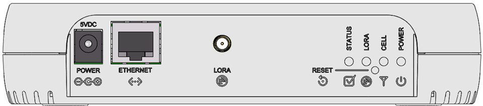
Ethernet only models with external LoRa antenna 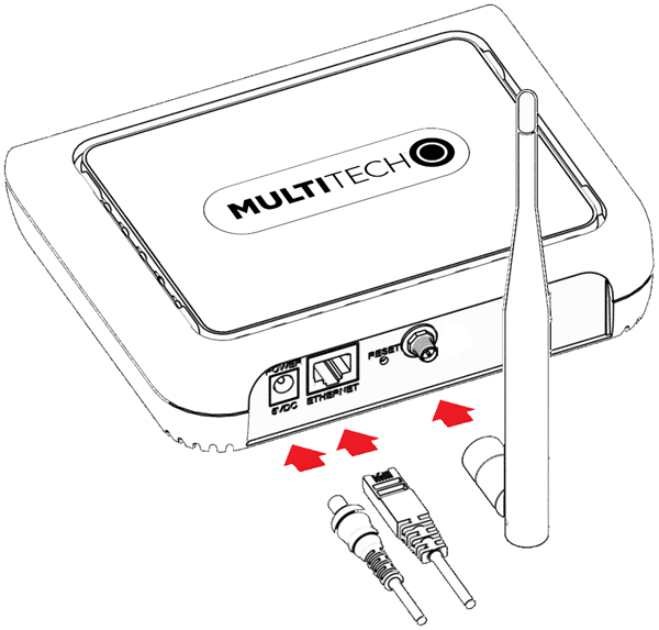 |
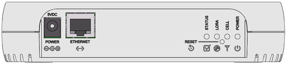
Ethernet only models, all internal antennas 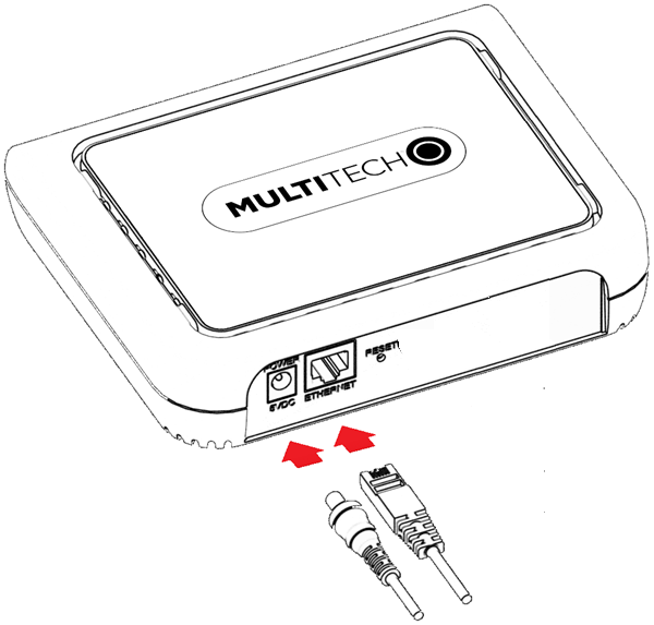 |
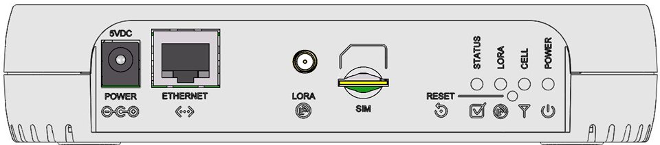
Cellular models with external LoRa antenna 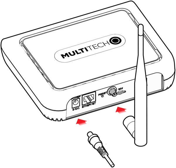 |
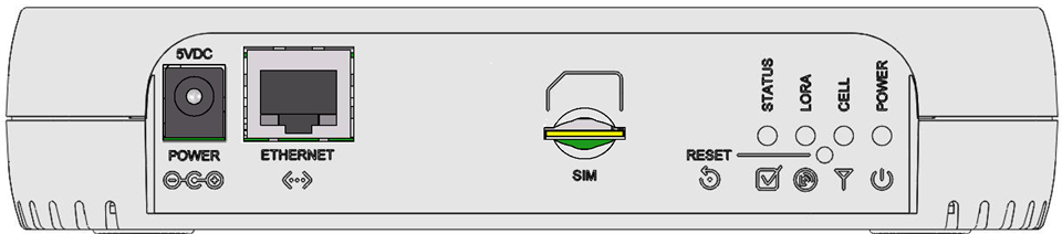
Cellular models, all internal antennas 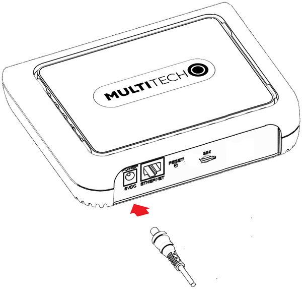 |
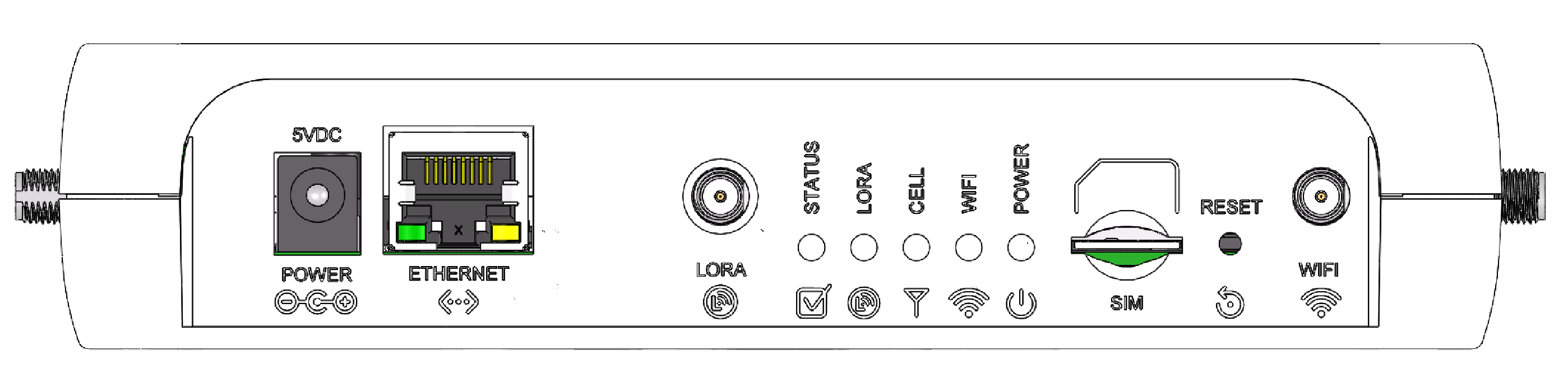
Connectors and LEDs
LoRa only models
LoRa and cellular radio models
LoRa only models with external LoRa antenna
LoRa and cellular radio models with external LoRa antenna
| Item | Description |
|---|---|
| Connectors | |
| Power | 5 Volt power jack. |
| Ethernet | RJ45 Ethernet jack. |
| Reset | Reset button. Reboots device or restores factory defaults. |
| LORA | RP-SMA connector for external LoRa antenna. (Select models) |
| SIM | Cellular models only. Micro (3FF) SIM slot. |
| LEDs | |
| STATUS | On (Solid): Firmware is booting. |
| Flashing: Blinks when operating system is fully loaded. | |
| Off: If this LED remains off one minute after power is applied, troubleshoot the device. | |
| LORA | On: Lights when LoRa software is active. |
| Flashing: Firmware upgrade mode. | |
| Off: LoRa services stopped. | |
| CELL (LoRa only) | Cellular models only. |
| CELL (cellular) | Cellular models only. |
| On: Firmware is booting. | |
| Fast flashing: Data transfer is ongoing. | |
| Slow flashing: Idle or network searching. If Power and LoRA LED are also flashing, firmware upgrade mode. | |
| Off: No cellular signal. Stays off if device does not have a radio. | |
| Power | On: Powered up, normal operation. |
| Slow Flashing: Firmware upgrade mode. | |
| Off: No power, either device disconnected from power or powered off. | |
| Ethernet Link (left LED on the Ethernet connector) | On: There is a valid Ethernet connection. |
| Flashing: Data is being sent or received on the Ethernet link. | |
| Ethernet Speed (right LED on the Ethernet connector) | On: The Ethernet is linked at 100 Mbps. |
| Off: The Ethernet is linked at 10 Mbps. | |
Wi-Fi Models
These connectors and LEDs are specific to MTCAP3 models with wi-fi.
| Item | Description |
|---|---|
| Connectors | |
| Power | 5 Volt power jack. |
| Ethernet | RJ45 Ethernet jack. |
| Reset | Reset button. Reboots device or restores factory defaults. |
| LORA | RP-SMA connector for external LoRa antenna. (Select models) |
| SIM | Cellular models only. Micro (3FF) SIM slot. |
| LEDs | |
| STATUS | On (Solid): Firmware is booting. |
| Flashing: Blinks when operating system is fully loaded. | |
| Off: If this LED remains off one minute after power is applied, troubleshoot the device. | |
| LORA | On: Lights when LoRa software is active. |
| Flashing: Firmware upgrade mode. | |
| Off: LoRa services stopped. | |
| CELL (LoRa only) | Cellular models only. |
| CELL (cellular) | Cellular models only. |
| On: Firmware is booting. | |
| Fast flashing: Data transfer is ongoing. | |
| Slow flashing: Idle or network searching. If Power and LoRA LED are also flashing, firmware upgrade mode. | |
| Off: No cellular signal. Stays off if device does not have a radio. | |
| WIFI | On: Wi-Fi radio is enabled. |
| Slow Flashing: Verifying firmware signature. | |
| Fast Flashing: Loading the kernel. | |
| Off: Wi-Fi radio is disabled. | |
| POWER | On: Powered up, normal operation. |
| Slowly Cycles On and Off: Loading initial Linux kernel. | |
| Off: No power, either device disconnected from power or powered off. | |
| Ethernet Link (left LED on the Ethernet connector) | On: There is a valid Ethernet connection. |
| Flashing: Data is being sent or received on the Ethernet link. | |
| Ethernet Speed (right LED on the Ethernet connector) | On: The Ethernet is linked at 100 Mbps. |
| Off: The Ethernet is linked at 10 Mbps. | |
Add the Device to Your Cloud Account
- QR Code
- Using a smartphone camera, scan the onboard QR code from the device serial label.
- Follow the instructions to sign in to your cloud account and quickly onboard the device.
- Manually
- Sign in to your cloud account.
- Select Gateways.
- Under Actions, select Add device.
- Enter the PID number from the device serial label.
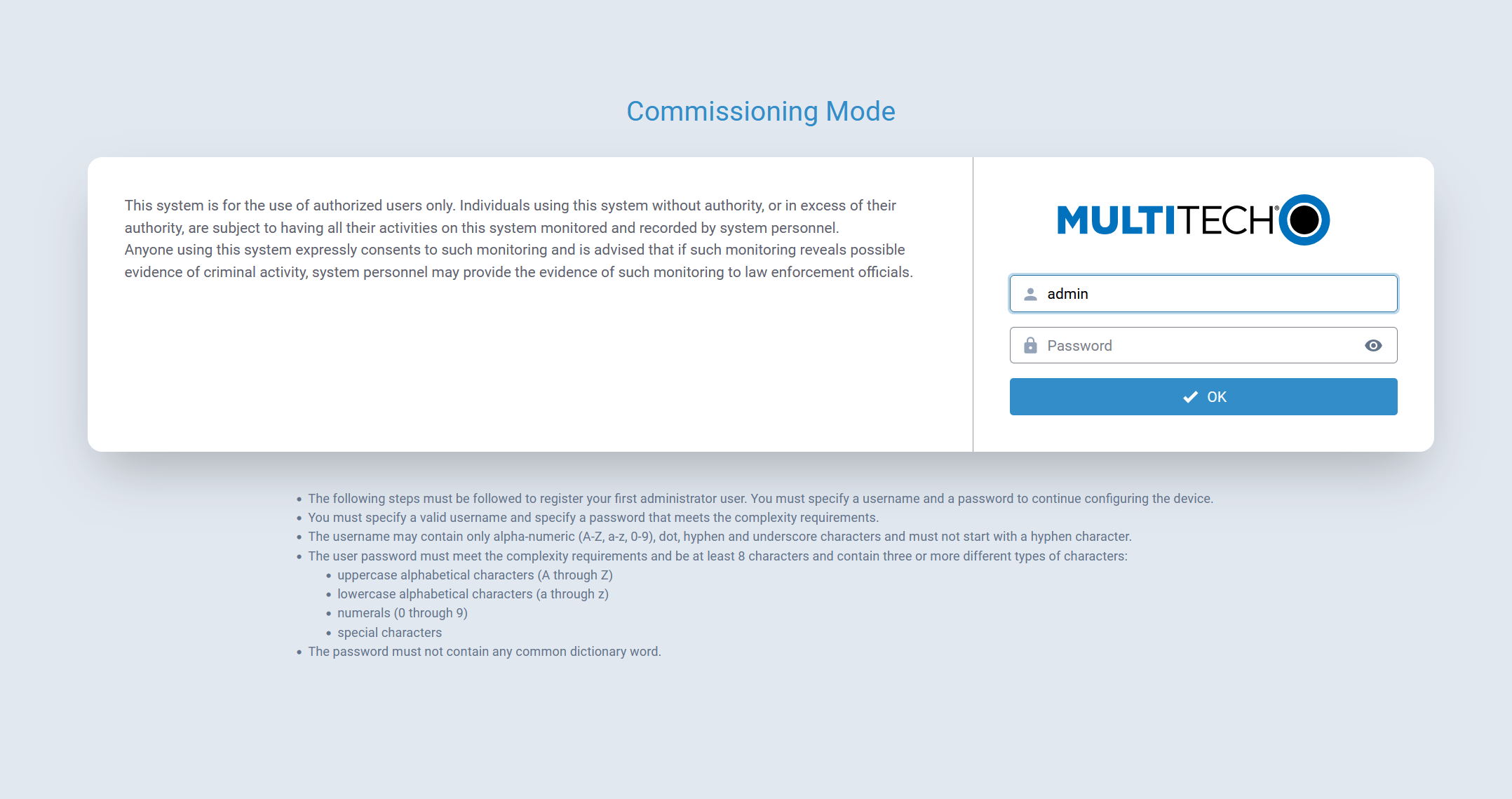
Commissioning Mode
The Conduit® AP 300 ships in what is called Commissioning Mode. As soon as the Conduit® AP 300 is reset to factory defaults or right after the manufacturing process is complete, the system is in Commissioning Mode.
The system attempts to connect to Device Manager (MT Cloud) as soon as there is an internet connection
The ETH0/LAN interface is configured with an IP of 192.168.2.1 and a netmask of 255.255.255.0.
Before proceeding, an Administrative User must be configured.
Configure the Administrative User
Perform the following procedure to create and configure the Administrative User:
Password Requirements Overview
- During Commissioning Mode, the minimum password length is 8 characters.
- After commissioning is complete and an Administrative User is created:
- The minimum password length for all new users is 15 characters.
- The minimum password length for any password change, including changes to the Administrative User’s own password, is 15 characters.
Note: These requirements align with NIST SP 800-63B guidance for single-factor authentication. - The minimum password length can be viewed or modified on the Password Complexity Rules configuration page.
- Devices upgraded from a previous release retain their existing password rules until the password complexity rules are manually changed.
Procedure
- Open a browser and enter the default IP address in the URL field,
192.168.2.1. Most browsers display a warning about HTTP addresses
being unsafe because of a self-signed certificate:
- For Edge, click Advanced and then Continue to 192.168.2.1.
- For Firefox, click Advanced and then click Accept the Risk and Continue.
- For Chrome, click Advanced and then Continue to 192.168.2.1 (unsafe).
- Enter a username for the Administrative User. Click OK. Follow on-screen instructions for usernames.
- Enter a password and click OK. Follow on screen instructions for a secure password.
- Enter the password again to confirm. Click OK.
- Log in to the Conduit® AP 300 using the new username and password.
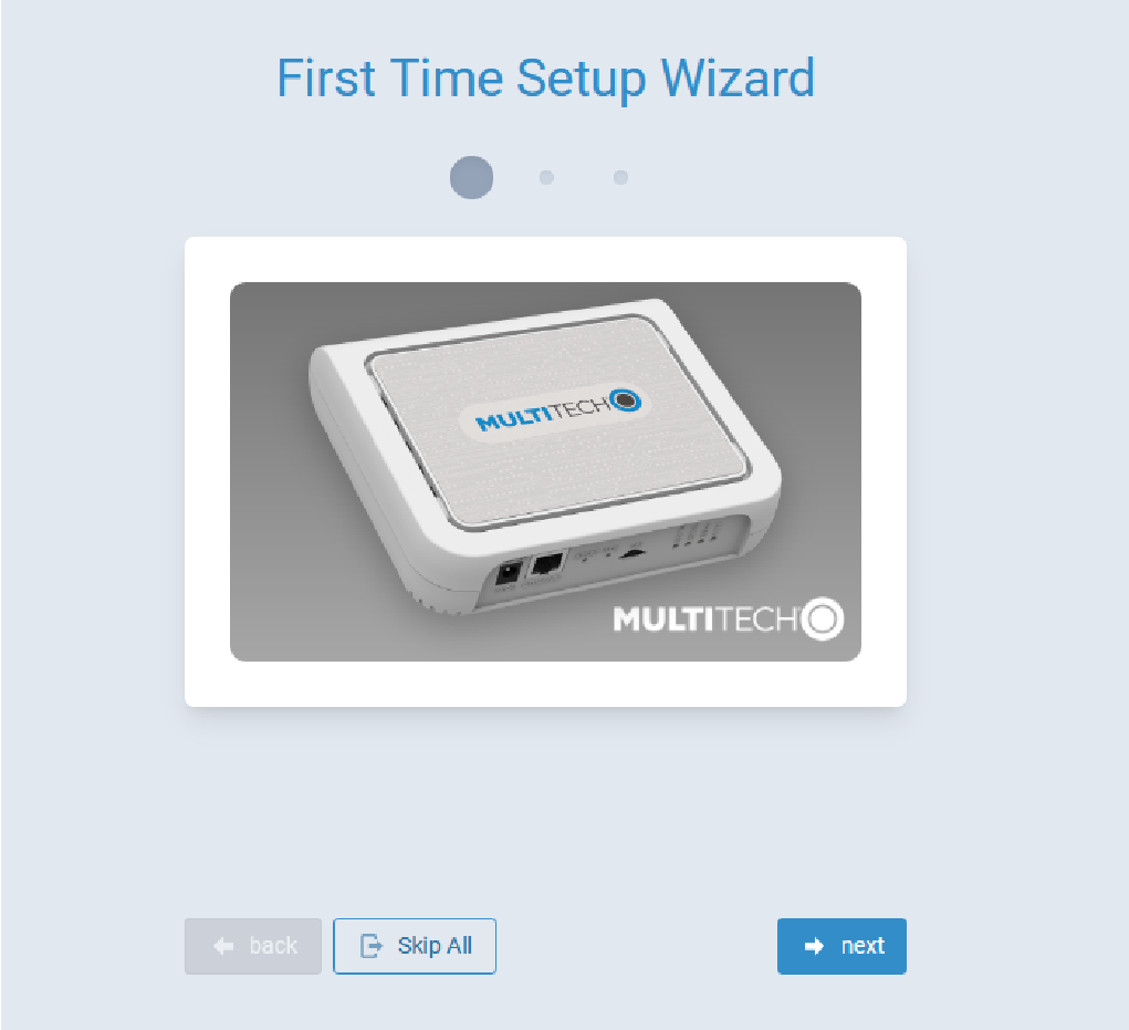
The First-Time Setup Wizard launches.
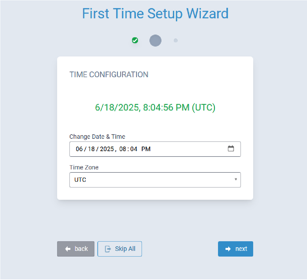
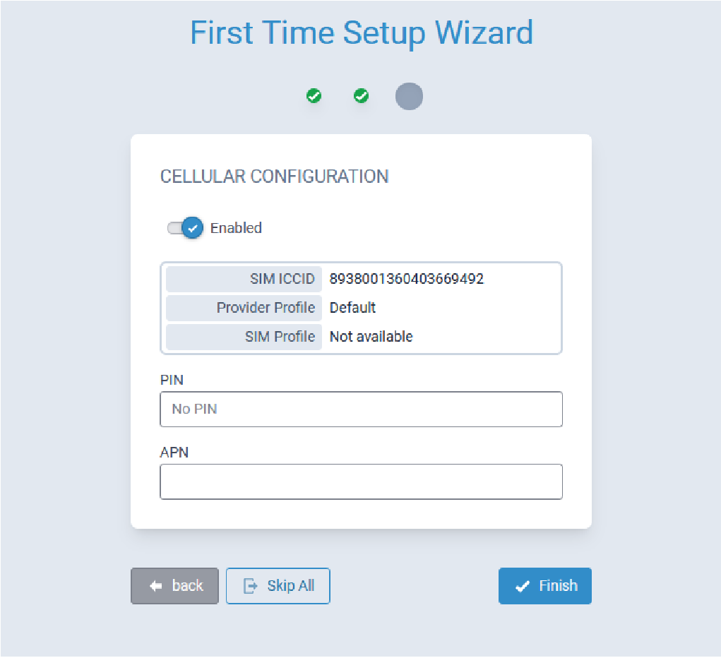
First Time Setup Wizard
- System date and time
- Cellular connectivity
Click Next to continue configuring the Conduit® AP 300.
Configure Network Router Mode
Perform the following procedure to configure the Conduit® AP 300 as a Network Router:
- Configure Date & Time and Time Zone to reflect the Conduit® AP 300's location.

- Click Next. Note: If the Conduit® AP 300 is not equipped with a radio modem (i.e., does not support Cellular operation,) click Finish.
- Configure PIN and APN if required.
- Click Finish.
Commissioning an Ethernet-Only MTCAP3
Network Configuration
The Ethernet interface on MTCAP3 (without cellular) operates as a DHCP client, meaning it does not use a predictable static IP (such as 192.168.2.1). Upon connection to a network, the device will request an IP from a DHCP server.
Locating the Device's IP Address
The assigned IP can typically be found using one of the following methods:
- DHCP Server Logs - most IT departments can retrieve the IP via MAC address or hostname (mtcap3-<serial_number>).
- Network Scanning Tools - utilities such as ARP, nmap, or similar tools may help identify the device’s IP.
Connecting to the Device
Once you’ve identified the assigned IP, you can access the device API or Web UI through that IP address in a browser.
mPower Configuration Settings
Home Menu
The Home menu comprises the following tabs:
- Dashboard
- Services
- Statistics
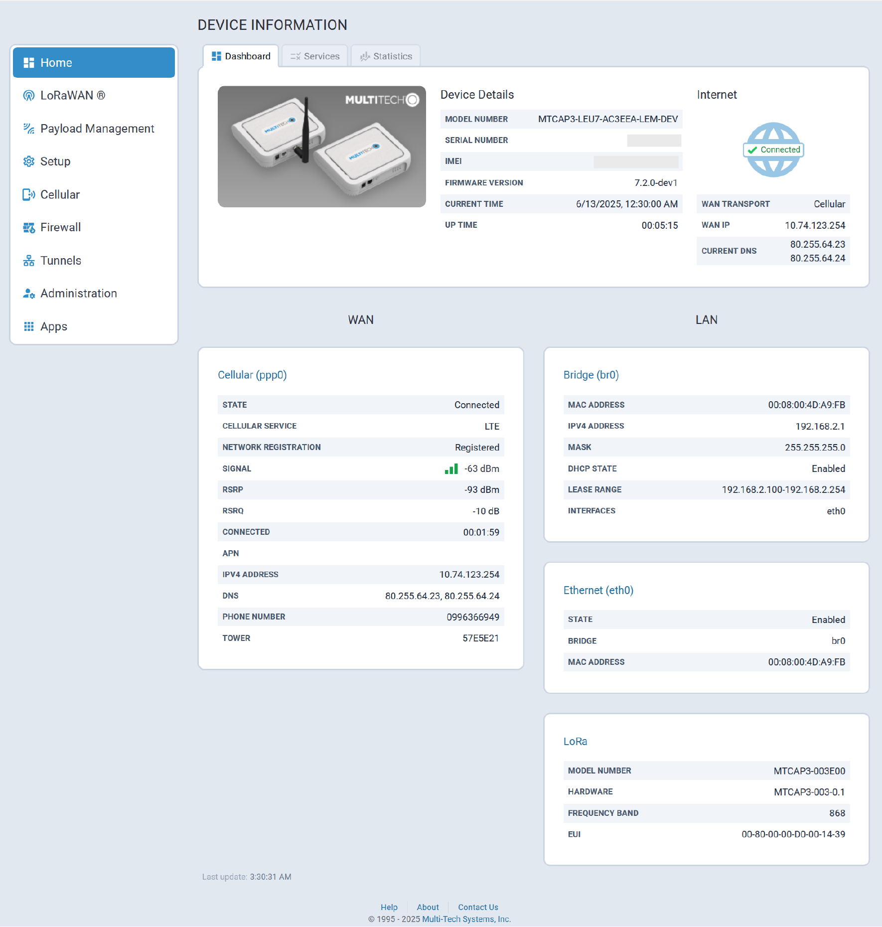
Dashboard Tab
The Dashboard tab provides a brief overview of the system state and configuration. The LoRa information only displays for MTCAP3-WiFi devices with LoRa.
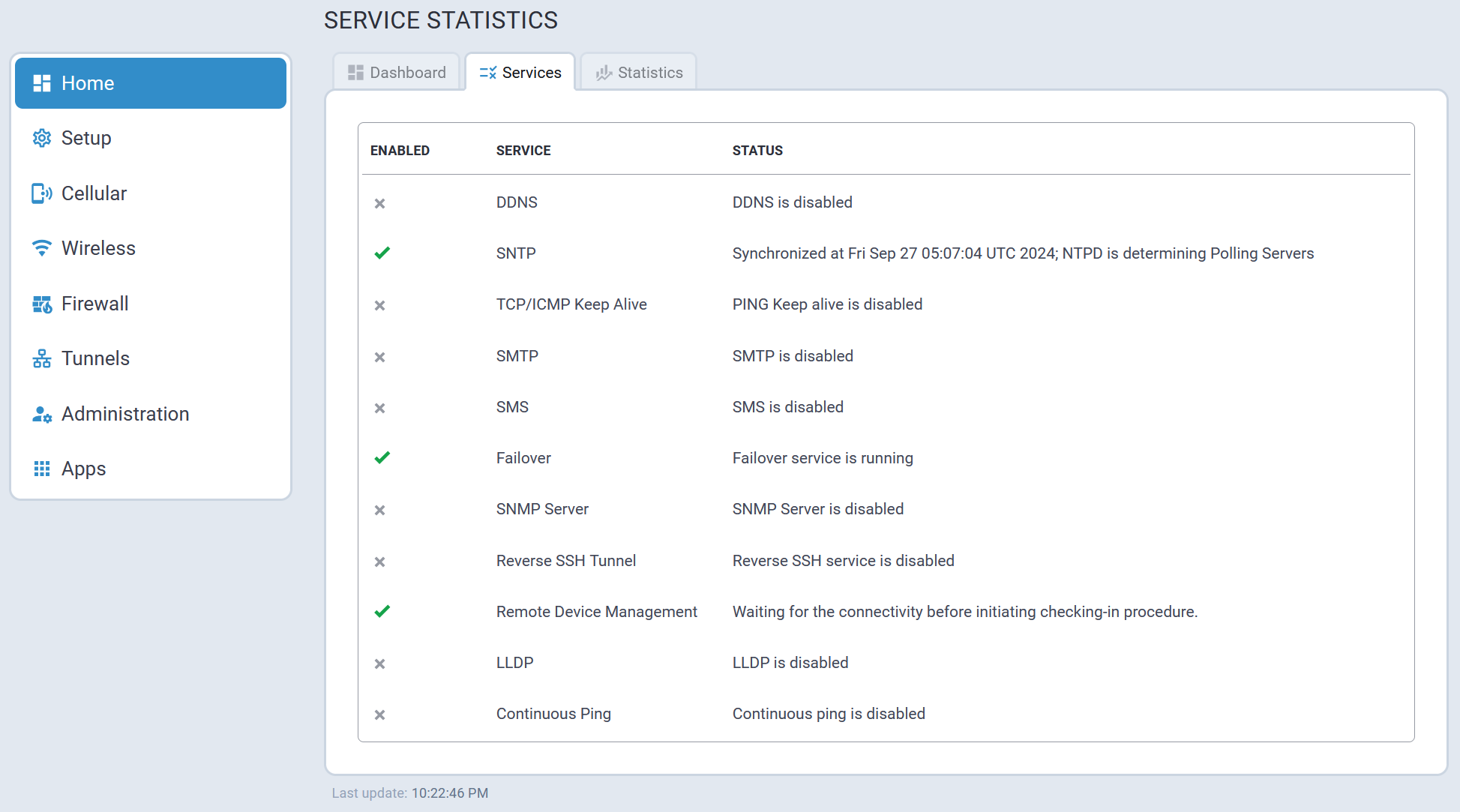
Services Tab
The Service Statistics tab lists the available services and their respective status.
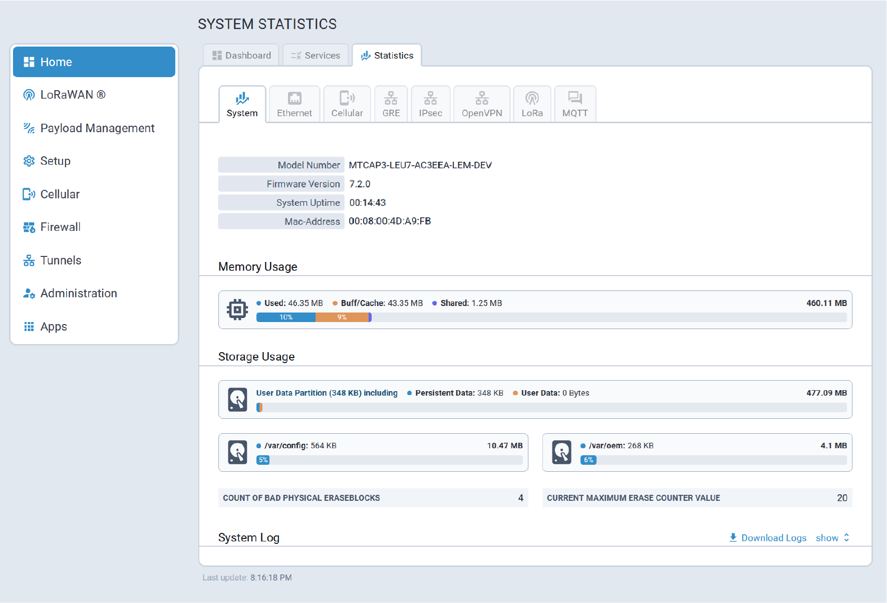
Statistics Tab
The System Statistics tab provides the following system information:
- System details, memory and storage usage, system log
- Ethernet interfaces statistics and logs
- Cellular statistics and logs
- GRE tunnels statistics and logs
- IPSec tunnels statistics and logs
- OpenVPN tunnels statistics and logs
LoRaWAN®
A typical LoRaWAN® page is illustrated here:
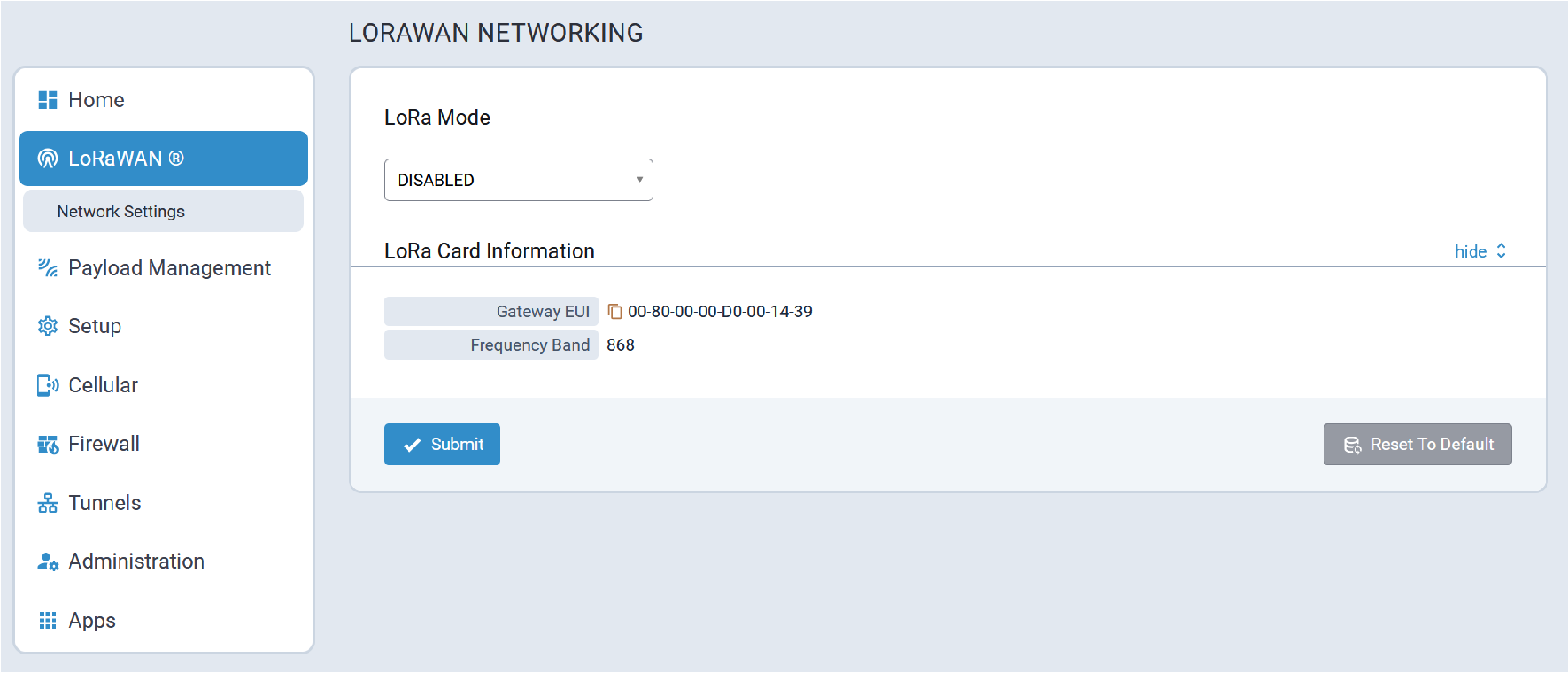
Gateways such as the Conduit® AP 300 can connect with end-devices/sensors to create an application network. Using the cloud-based Lens interface, LoRa application networks, including gateway and end-devices, can easily be managed.
When the LoRa Mode is set to Network Server, the Conduit® AP 300 acts as a network server allowing end-points to join with the correct credentials on the correct frequency and sub-band.
- 915 (AS, AU, KR, IL, and US)
- In the US, the 915 band supports 8 sub-bands.
- 868 (EU, IN, and RU)
- In the EU, the 868 band has three default channels and five configurable channels.
- Global 2400 (ISM)
- For specific industrial, scientific, and medical applications globally, the ISM 2400 band has three default channels.
The transmit (TX) power setting controls the transmission power of the gateway.
The Rx 1 DR Offset and RX 2 Datarate are sent with a join response to configure the data rates used for receive windows.
The offset is applied to the downlink data rate for reception on the first window according to LoRa WAN standards.
If LoRa two cards are installed, the system displays information for both cards: FPGA Version and Frequency Band using (ap1) and (ap2) labels.
- The system chooses the card to activate based on the selected channel plan.
- This allows 868 and 915 cards to be installed. Only one card is be active at any time.
- Two v1.5 915 or 868 cards can be used as long as they are the same frequency band.
Detailed LoRaWAN network configuration information is provided in the following sections.
Network Settings
The set of network configuration parameters displayed depends on the selected LoRa Mode.
- NETWORK SERVER
- PACKET FORWARDER
- BASIC STATION
- DISABLED
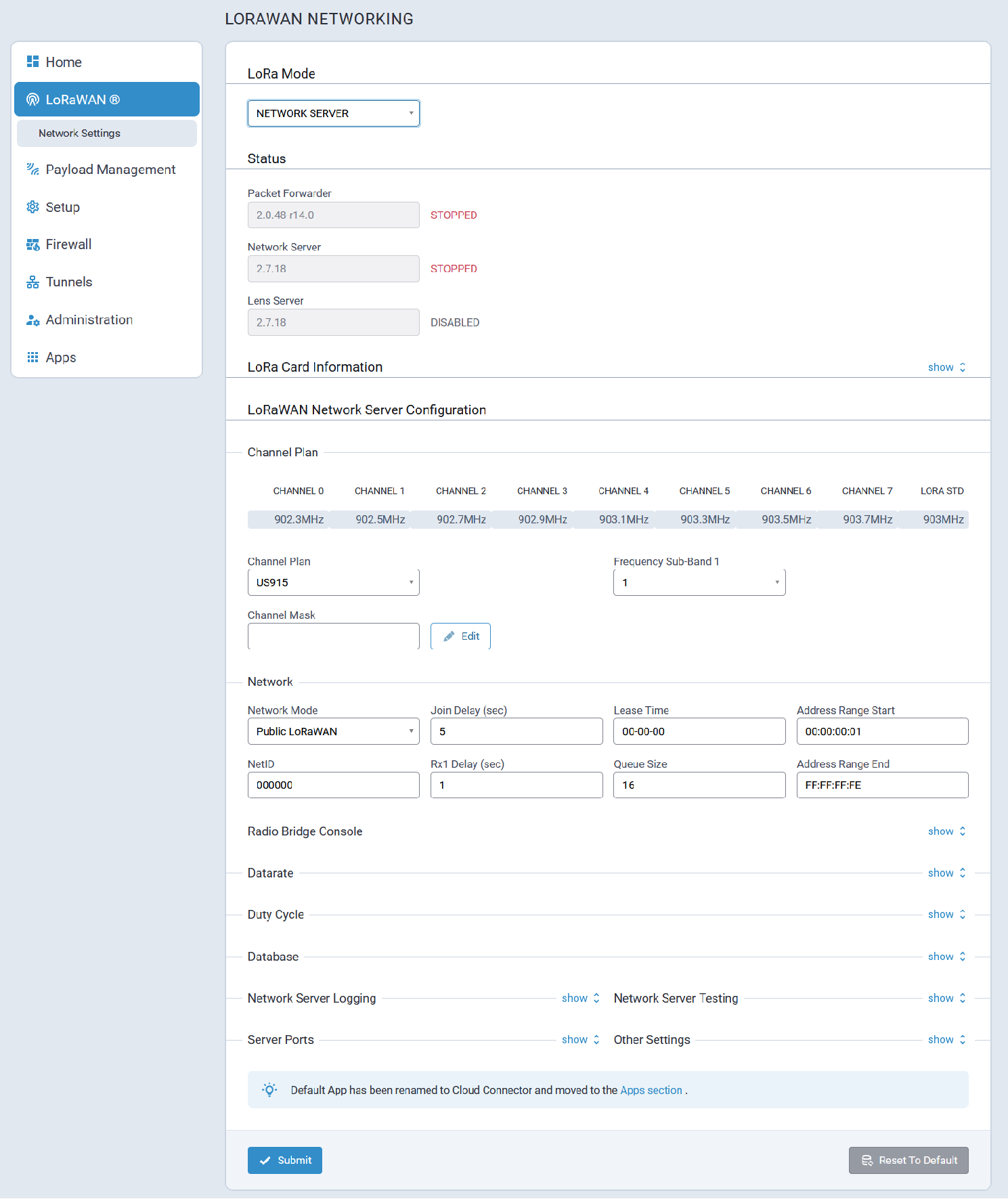
Network Server Mode
Typical Network Server mode configuration parameters are shown here:
Status
LoRaWan Network Server status information is shown here:
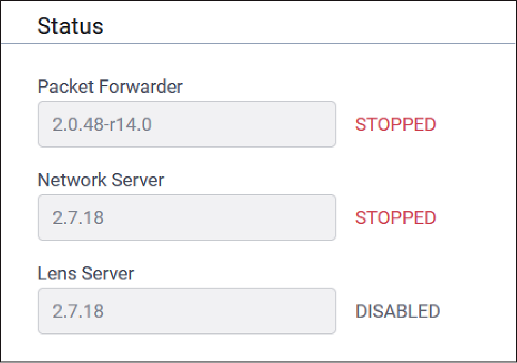
| Parameter | Default Value | Description |
|---|---|---|
| Packet Forwarder | Depends on latest software version | Packet Forwarder software version |
| Packet Forwarder Status | If configured properly, RUNNING | Packet Forwarder status. Values include RUNNING, RESTARTED, or DISABLED. |
| Network Server | Depends on latest software version | Network Server software version |
| Network Server Status | If configured properly, RUNNING | Network Server status. Values include RUNNING, RESTARTED, or DISABLED. |
| Lens Server | Depends on latest software version | Lens Server software version |
| Lens Server Status | If configured properly, RUNNING | Lens Server status. Values include RUNNING, RESTARTED, or DISABLED. |
LoRa Card Information
Typical LoRa Card parameter information is provided here:
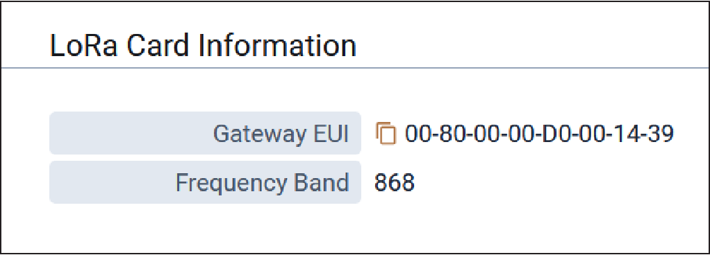
| Parameter | Default Value | Description |
|---|---|---|
| Gateway EUI | N/A | Gateway ID of Conduit, queried from the LoRa card (if present). |
| Frequency Band | Depends on LoRa card | Frequency band set based on the installed LoRa peripheral. |
| FPGA Version | Depends on LoRa card | FPGA firmware version of the installed LoRa card. |
| Upgrade FPGA | N/A | Click on link to upgrade FPGA firmware on the LoRa card, if a later version is available. |
| Current Version | Depends on LoRa Card | Current FPGA firmware version of the installed LoRa card. |
| Upgrade Version | Depends on LoRa Card | Upgrade version of FPGA firmware if available. If this field displays an upgrade version, click Start to upgrade the firmware. If this field displays No Options Available, then you already have the latest version and you can click Cancel. |
LoRaWAN Network Server Configuration
Typical LoRaWAN Network Server configuration parameters are shown here:
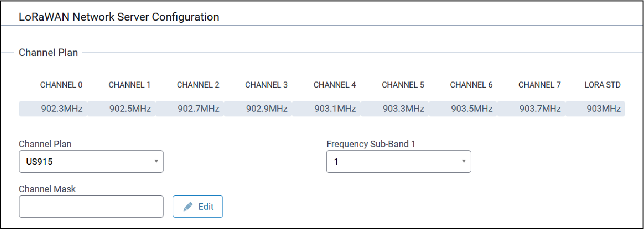
| Parameter | Default Value | Description |
|---|---|---|
| Channel Plan | US915: 915, AU915: 915, AS923-1: 915, AS923-2: 915, AS923-3: 915, AS923-4: 915, KR920: 915, EU868: 868, IN865: 868, RU864: 868, ISM2400: 2400 | LoRaWAN channel plan used for the upstream and downlink
frequencies and datarates. Values are US915, EU868, IN865, AU915,
AS923-1, AS923-2, AS923-3, AS923-4, KR920, RU864, or ISM2400.
Available channel plans depend on the type of LoRa card
installed. For more details about each Channel Plan, refer to the RP2-1.0.3 LoRaWAN® Regional Parameters document on the LoRa Alliance website, https://lora-alliance.org/. |
| Additional Channels | Depends on channel plan selected | A set of channels are configured based on this setting (MHz).
Frequencies supported depends on channel plan selected. v2.1
Geolocation GW - default channels must be included in the configured
range. The RU864 plan uses the following channels when configured
with the default settings of 0: Radio 0: 868.9 MHz, 869.1 MHz Radio 1: 864.1 MHz, 864.3 MHz, 864.5 MHz, 864.7 MHz, 864.9 MHz. |
| Additional Channels 2 | Depends on channel plan selected | A set of channels are configured based on this setting (MHz).
Frequencies supported depends on channel plan selected. v2.1
Geolocation GW - Configurable for the range within the entire
band.The RU864 plan will use the following channels when configured
with the default settings of 0: Radio 0: 868.9 MHz, 869.1 MHz Radio 1: 864.1 MHz, 864.3 MHz, 864.5 MHz, 864.7 MHz, 864.9 MHz. |
| Channel Mask | N/A | Mask of available channels. Leave empty to enable only selected
sub-band or set as desired. Click the Edit button to select your
desired channel mask(s) by checking the box under the available list
of channels. Override channel mask to include coverage provided by
additional gateways. US/AU 64-channel: 00FFFFFFFFFFFFFFFFFF and
EU/AS/IN/KR: 00FF. Combine the following FSB masks to support more
than 8 channels. Settings will be sent to end-devices on first
downlink after OTA join:
|
| Frequency Sub-Band | 1 | For US and AU only, 8 sub-bands are available. |
| Frequency Sub-Band 2 | 1 | For US and AU only, 8 sub-bands are available (for extra LoRa Card). |
| Enable Diversity | Unchecked | Enable use of two LoRa cards. |
| Enable LBT | Unchecked | Enable Listen Before Talk. Note: Requires
FPGA v33 or v61.
|
| Max EIRP | 20 | Maximum uplink transmit power of end-devices (in dBm) |
| Dwelltime Up | 0 (no limit) | Maximum uplink dwell-time for region (ms). 0 : no limit and 1 : 400 ms (depends on region). |
| Dwelltime Down | 0 (no limit) | Maximum downlink dwell-time for region (ms). 0 : no limit and 1 : 400 ms (depends on region). |
Network Configuration
Typical Network configuration parameters are shown here:
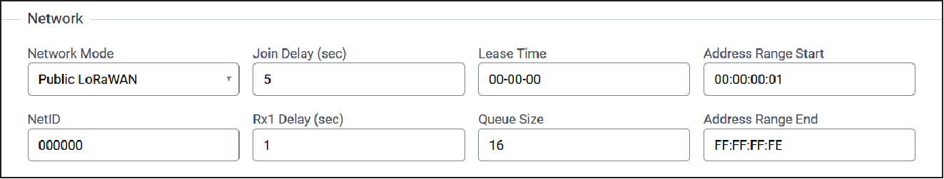
| Parameter | Default Value | Description |
|---|---|---|
| Network Mode | Public LoRaWAN | Set Network Mode: Private MTS (sync word: 0x12 and US/AU) Downlinks per FrequencySubBand) Public LoRaWAN (sync word: 0x34) Private LoRaWAN (sync word: 0x12) |
| Join Delay (sec) | Depends on selected Network Mode value.
|
Number of seconds before receive windows are opened for join. Must match Dot settings. Range: 1-15 |
| Lease Time (dd-hh-mm) | 00-00-00 | Amount of time until a successful join expires. |
| Address Range Start | 00:00:00:01 | Start address to assign to OTA joining motes. |
| NetID | 000000 | LoRaWAN NetID setting for assigning network address and beacons. |
| Rx1 Delay (sec) | 1 | Number of seconds before receive windows are opened. Must match Dot settings. Range: 1-15 |
| Queue Size | 16 | Number of downlink messages to hold per node. |
| Address Range End | FF:FF:FF:FE | End address to assign to OTA joining motes. |
Radio Bridge Console Configuration
Typical Radio Bridge Console configuration parameters are shown here:
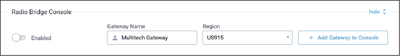
| Parameter | Default Value | Description |
|---|---|---|
| Enabled | TBD | TBD |
| Gateway Name | TBD | TBD |
| Region | TBD | TBD |
Datarate Configuration
Typical Datarate configuration parameters are shown here:
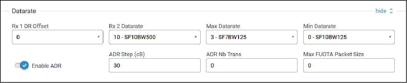
| Parameter | Default Value | Description |
|---|---|---|
| Rx 1 DR Offset | 0 | Offset applied to upstream data rate for downstream data rate on first receive window. US: 0-4, EU/RU: 0-5, AS/IN: 0-7, AU: 0-7, KR: 0-5. |
| Rx 2 Datarate | 10 (For US/AU), 2 (For all others) | Datarate for second receive window. US: 8-13, EU/IN/AS: 0-7, AU: 8-13, KR: 0-5. |
| Max Datarate | 0 | Maximum datarate to use for ADR. US: 0-4, EU/AS/RU: 0-7, AU: 0-6, KR: 0-5, IN: 1-5,7. |
| Min Datarate | 0 | Minimum datarate to use for ADR. US: 0-4, EU/AS/RU: 0-7, AU: 0-6, KR: 0-5, IN: 1-5,7. |
| Enable ADR | TBD | TBD |
| ADR Step (cB) | 30 | Step between each datarate setting for ADR (minimum: 25). |
| ADR Nb Trans | TBD | TBD |
| Max FUOTA Packet Size | N/A | Maximum packet size used for FUOTA downloads. |
Duty Cycle Configuration
Typical Duty Cycle configuration parameters are shown here:
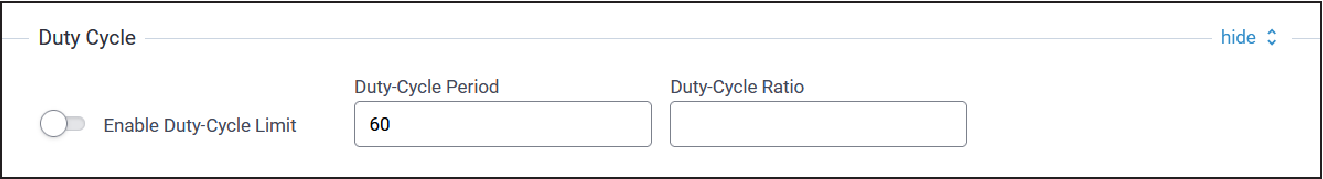
| Parameter | Default Value | Description |
|---|---|---|
| Enable Duty-Cycle Limit | Disabled | Allows the gateway to configure and enforce duty-cycle window limits on transmissions. |
| Duty-Cycle Period | 60 | Number of minutes in sliding windows for duty cycle restrictions (for EU only). |
| Duty-Cycle Ratio | N/A | Amount of time on-air allowed per window. |
Database Configuration
Typical Database configuration parameters are shown below:
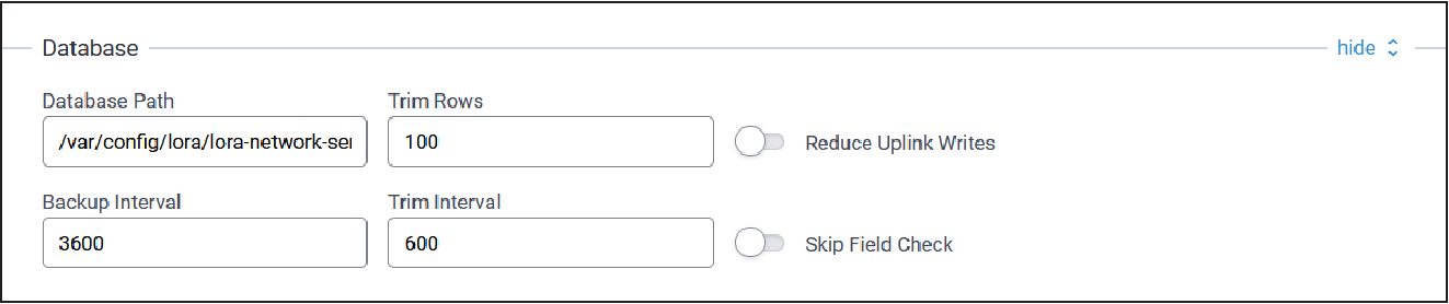
| Parameter | Default Value | Description |
|---|---|---|
| Database Path | var/config/lora/lora-network-server.db | Path to backup database in non-volatile memory |
| Trim Size | 100 | Maximum size of packet tables to keep in database |
| Reduce Uplink Writes | Disabled (unchecked) | Write uplink data to database every 100 packets or 5 minutes to increase uplink throughput |
| Backup Interval | 3600 | Interval in seconds to backup the database to flash |
| Trim Interval | 600 | Interval in seconds to run the trim packet data tables command |
| Skip Field Check | Disabled (unchecked) | Skip checking JSON fields of UDP packets from packet forwarder, may increase uplink throughput |
Network Server Logging Configuration
Typical Network Server Logging configuration parameters are shown here:
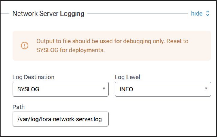
| Parameter | Default Value | Description |
|---|---|---|
| Log Destination | Syslog | Select the type logging destination, either Syslog or File Note: Select File only for debugging purposes
to avoid running out of Conduit® AP 300 RAM.
|
| Log Level | INFO | Select the log level of the messages to be logged. Choose from drop-down: Info, Error, Warning, Debug, Trace, and Maximum. Maximum will provide all messages. |
| Path | blank | Specify the log file location. |
Network Server Testing Configuration
Typical Network Server Testing configuration parameters are shown here:
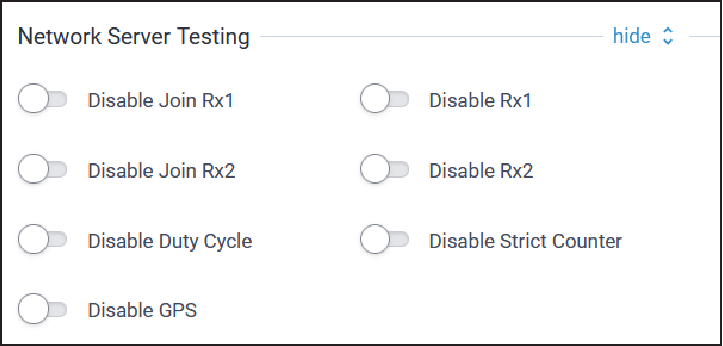
| Parameter | Default Value | Description |
|---|---|---|
| Disable Join Rx1 | Disabled | Disable sending join accept message in Rx1. |
| Disable Rx1 | Disabled | Disable sending downlink messages in Rx1. |
| Disable Join Rx2 | Disabled | Disable sending join accept message in Rx2. |
| Disable Rx2 | Disabled | Disable sending downlink messages in Rx2. |
| Disable Duty Cycle | Disabled | Disable duty cycle restrictions (this is for testing purposes only - do not use for deployments). |
| Disable Strict Counter | TBD | TBD |
| Disable GPS | TBD | TBD |
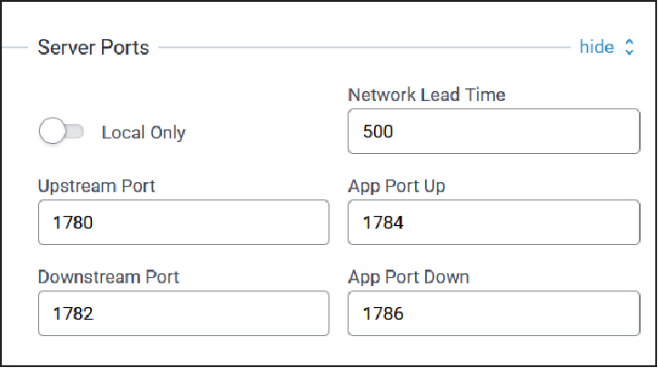
Server Ports Configuration
Typical Server Port configuration parameters are shown here:
| Parameter | Default Value | Description |
|---|---|---|
| Local Only | Enabled (checked) | Configure local ports only |
| Network Lead Time | TBD | TBD |
| Upstream Port | 1780 | Upstream port |
| App Port Up | 1784 | Application port up |
| Downstream Port | 1782 | Downstream port |
| App Port Down | 1786 | Application port down |
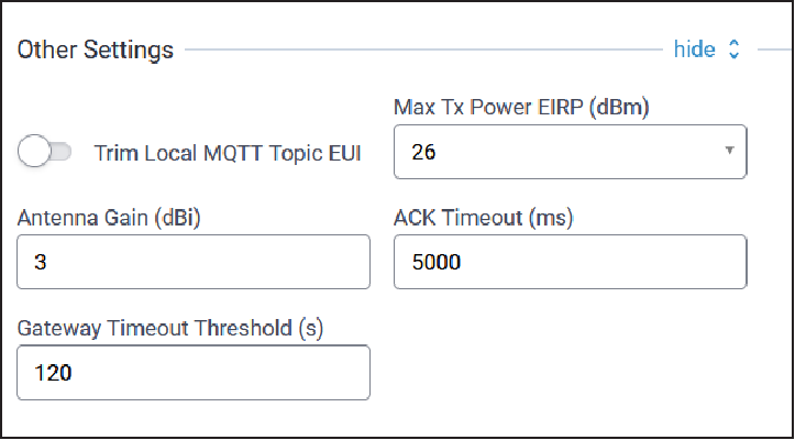
Other Settings
Other configuration parameters are shown here:
| Parameter | Default Value | Description |
|---|---|---|
| Trim Local MQTT Topic EUI | TBD | TBD |
| Max Tx Power EIRP (dBm) | N/A | Maximum transmitted power with antenna gain. |
| Antenna Gain (dBi) | 3 | Gain of the configured antenna
Valid values: -128 to +128 |
| ACK Timeout (ms) | TBD | TBD |
| Gateway Timeout Threshold (s) | TBD | TBD |
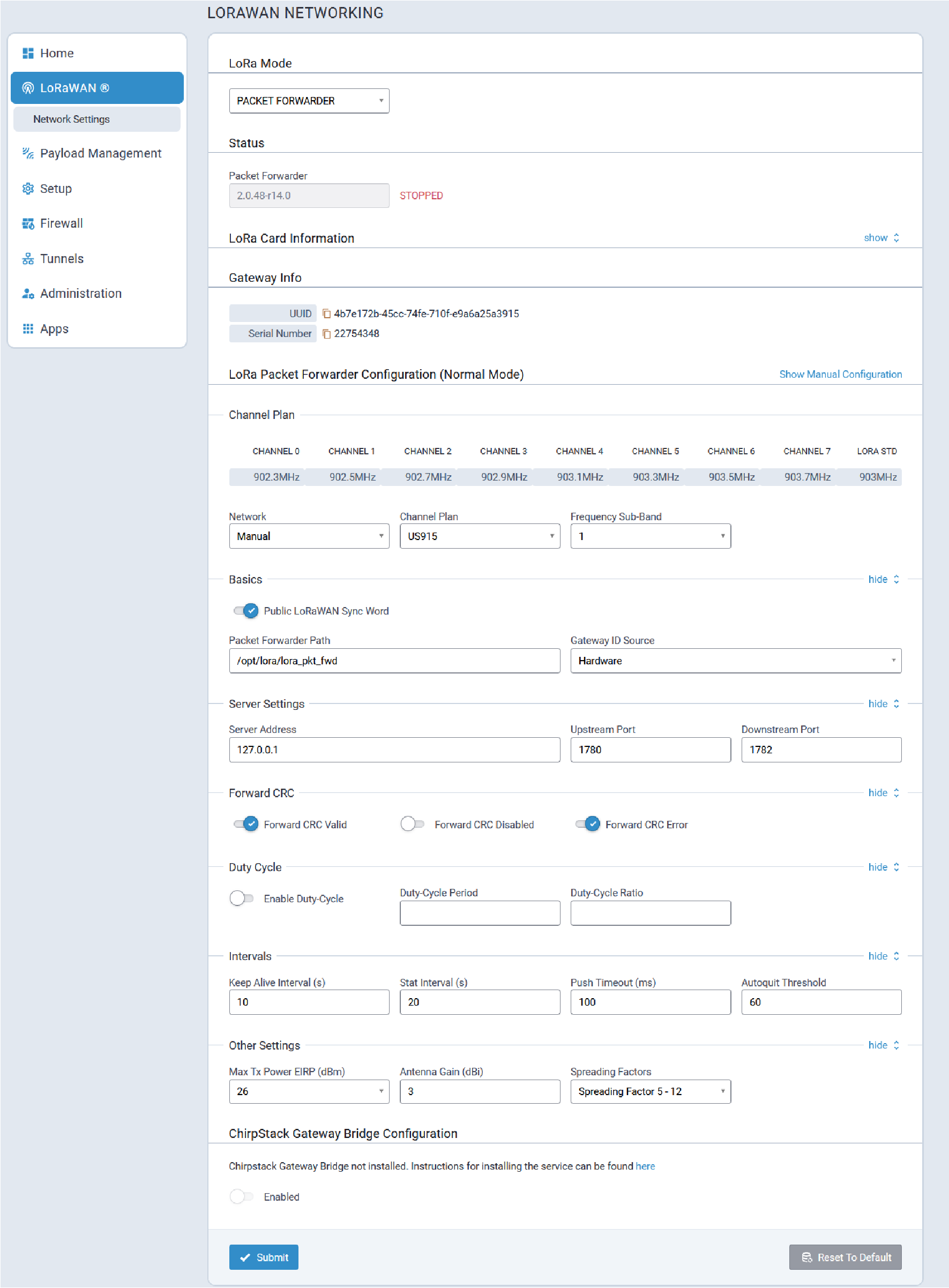
Packet Forwarder Mode
Typical Packet Forwarder mode configuration parameters are shown here:
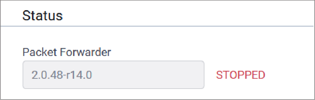
Status
LoRaWan Packet Forwarder status information is shown here:
| Parameter | Default Value | Description |
|---|---|---|
| Packet Forwarder | Depends on latest software version | Packet Forwarder software version |
| Packet Forwarder Status | If configured properly, RUNNING | Packet Forwarder status. Values include RUNNING, RESTARTED, or DISABLED. |
LoRa Card Information
Typical LoRa Card parameter information is provided here:
| Parameter | Default Value | Description |
|---|---|---|
| Gateway EUI | N/A | Gateway ID of Conduit, queried from the LoRa card (if present). |
| Frequency Band | Depends on LoRa card | Frequency band set based on the installed LoRa peripheral. |
| FPGA Version | Depends on LoRa card | FPGA firmware version of the installed LoRa card. |
| Upgrade FPGA | N/A | Click on link to upgrade FPGA firmware on the LoRa card, if a later version is available. |
| Current Version | Depends on LoRa Card | Current FPGA firmware version of the installed LoRa card. |
| Upgrade Version | Depends on LoRa Card | Upgrade version of FPGA firmware if available. If this field displays an upgrade version, click Start to upgrade the firmware. If this field displays No Options Available, then you already have the latest version and you can click Cancel. |
Gateway Info
Typical Gateway Info is shown here:
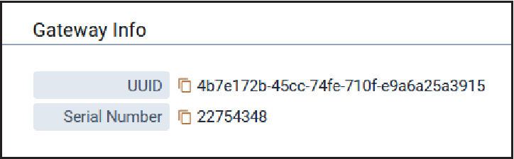
| Parameter | Default Value | Description |
|---|---|---|
| UUID | N/A |
Universally Unique Identifier (128-bit ID) |
| Serial Number | N/A | Serial number for the Conduit® AP 300 |
LoRa Packet Forwarder Configuration (Normal Mode)
To manually configure the Packet Forwarder, click on the Show Manual Configuration link as shown below.
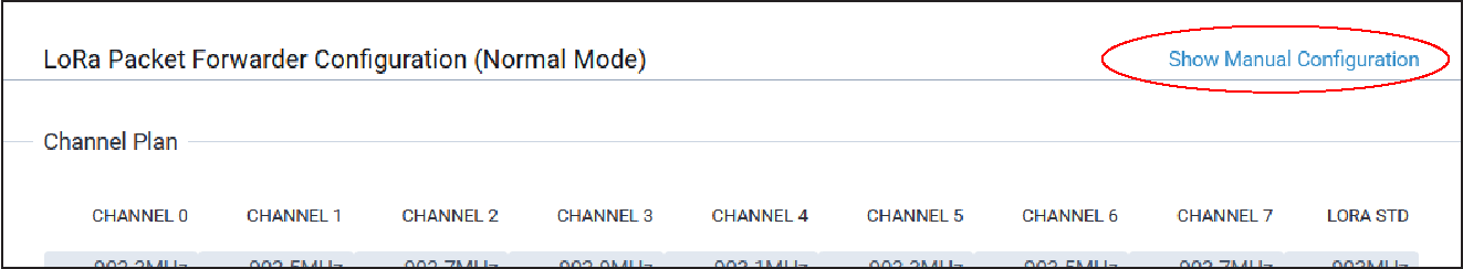
For a Dual Packet Forwarder, both cards may be manually configured provided two LoRa cards are installed. This allows different channel plans or network servers to be configured for each forwarder.
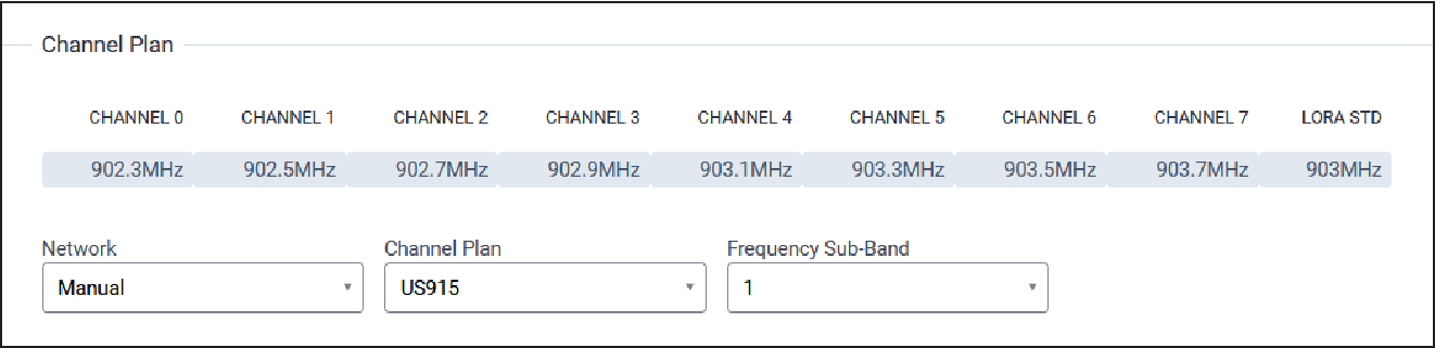
Channel Plan
Typical Channel Plan configuration parameters are shown here:
| Parameter | Default Value | Description |
|---|---|---|
| Network | Manual | Select the network for Packet Forwarder mode including Manual (user
determined), Radio Bridge Chirpstack, The Things Network, Senet, and
Loriot. Note: For Manual configuration, if SR
paths are not provided, the system automatically finds/specifies
them.
|
| Channel Plan | US915: 915AU915: 915, AS923-1: 915, AS923-2: 915, AS923-3: 915, AS923-4: 915, KR920: 915, EU868: 868, IN865: 868, RU864: 868, ISM2400: 2400 |
LoRaWAN channel plan used for the upstream and downlink frequencies and datarates. Values are US915, EU868, IN865, AU915, AS923-1, AS923-2, AS923-3, AS923-4, KR920, RU864, or ISM2400. Available channel plans depend on the type of LoRa card installed. For more details on each Channel Plan, refer the RP2-1.0.3 LoRaWAN® Regional Parameters document on the LoRa Alliance website, https://lora-alliance.org/. |
| Frequency Sub-Band | 1 |
For US and AU only, 8 sub-bands are available. |
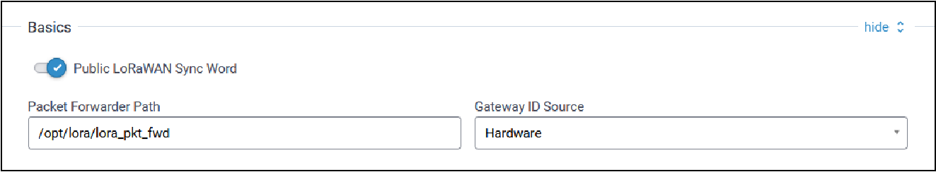
Basics
Typical Basic configuration parameters are shown here:
| Parameter | Default Value | Description |
|---|---|---|
| Public LoRaWAN Sync Word | Disabled |
Enables/disables public mode:
|
| Packet Forwarder Path | opt/lora/lora_pkt_fwd |
Path to the packet forwarder binary file to execute. |
| Gateway ID Source | Manual | Valid values are:
|
Server Settings
Typical Server Settings configuration parameters are shown here:
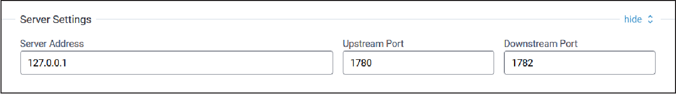
| Parameters | Default Value | Description |
|---|---|---|
| Server address | N/A | Server IP address to forward received uplink packets and transmit
received downlink packets. The system provides the default address for
The Things Network (based on your channel plan) and Semtech
Demo. Refer to the router addresses table of The Things Network for the list of specific addresses based on channel plan https://www.thethingsnetwork.org/docs/gateways/packet-forwarder/semtech-udp/. If you choose The Things Network with the AS923 channel plan, there
are four different addresses available.
Note: No server addresses are available for The Things Network when
using IN865 or RU864 channel plans.
|
| Upstream Port | N/A | IP Port to send received uplinks to. The system provides default ports for The Things Network and Semtech Demo. |
| Downstream Port | N/A | IP Port to connect to network server for downlink packets. The system provides default ports for The Things Network and Semtech Demo. |
Forward CRC
Typical Forward CRC (cyclic redundancy check) configuration parameters are shown here:
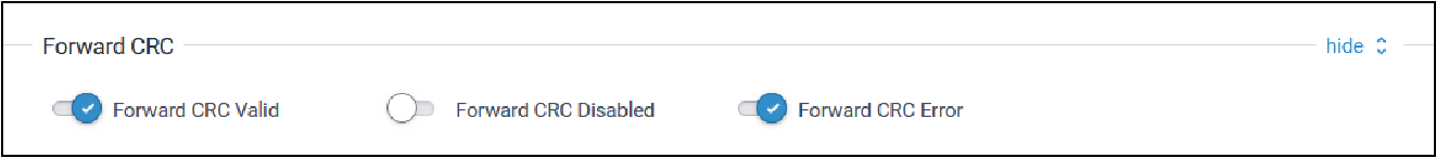
| Parameter | Default Value | Description |
|---|---|---|
| Forward CRC Valid | Enabled | When enabled, packets received with CRC Valid are sent to the network server. |
| Forward CRC Disabled | Disabled | When enabled, packets received with CRC Disabled are sent to the network server. |
| Forward CRC Error | Enabled | When enabled, packets received with CRC Errors are sent to the network server. |
Duty Cycle
Typical Duty Cycle configuration parameters are shown here:
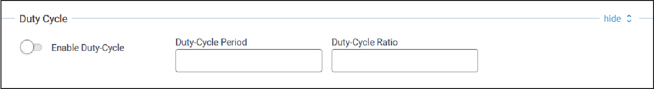
| Parameter | Default Value | Description |
|---|---|---|
| Enable Duty-Cycle | Disabled | When enabled, the gateway configures and enforces duty‑cycle window limits on transmissions. |
| Duty-Cycle Period | 60 | Number of minutes in sliding windows for duty‑cycle restrictions (for EU only). |
| Duty-Cycle Ratio | N/A | Amount of time on‑air allowed per window. |
Intervals
Typical Intervals configuration parameters are shown here:
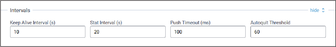
| Parameter | Default Value | Description |
|---|---|---|
| Keep Alive Interval (s) | 10 | Interval to send a ping to the network server. |
| Stat Interval (s) | 20 | Interval to update the network server with gateway statistics. |
| Push Timeout (ms) | 100 | Timeout default. |
| Autoquit Threshold | 60 | Number of messages sent without acknowledgment from the network server. |
Other Settings
Typical Other Settings configuration parameters are shown here:
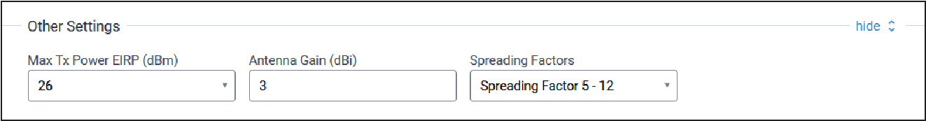
| Parameter | Default Value | Description |
|---|---|---|
| Max TX Power EIRP (dBm) | N/A | Transmit power limit with antenna gain (dBm) |
| Antenna Gain (dBi) | 3 | Gain of configured antenna Valid values are -128 to +128 dBi |
| Spreading Factors | Spreading Factors 5 - 12 | TBD |
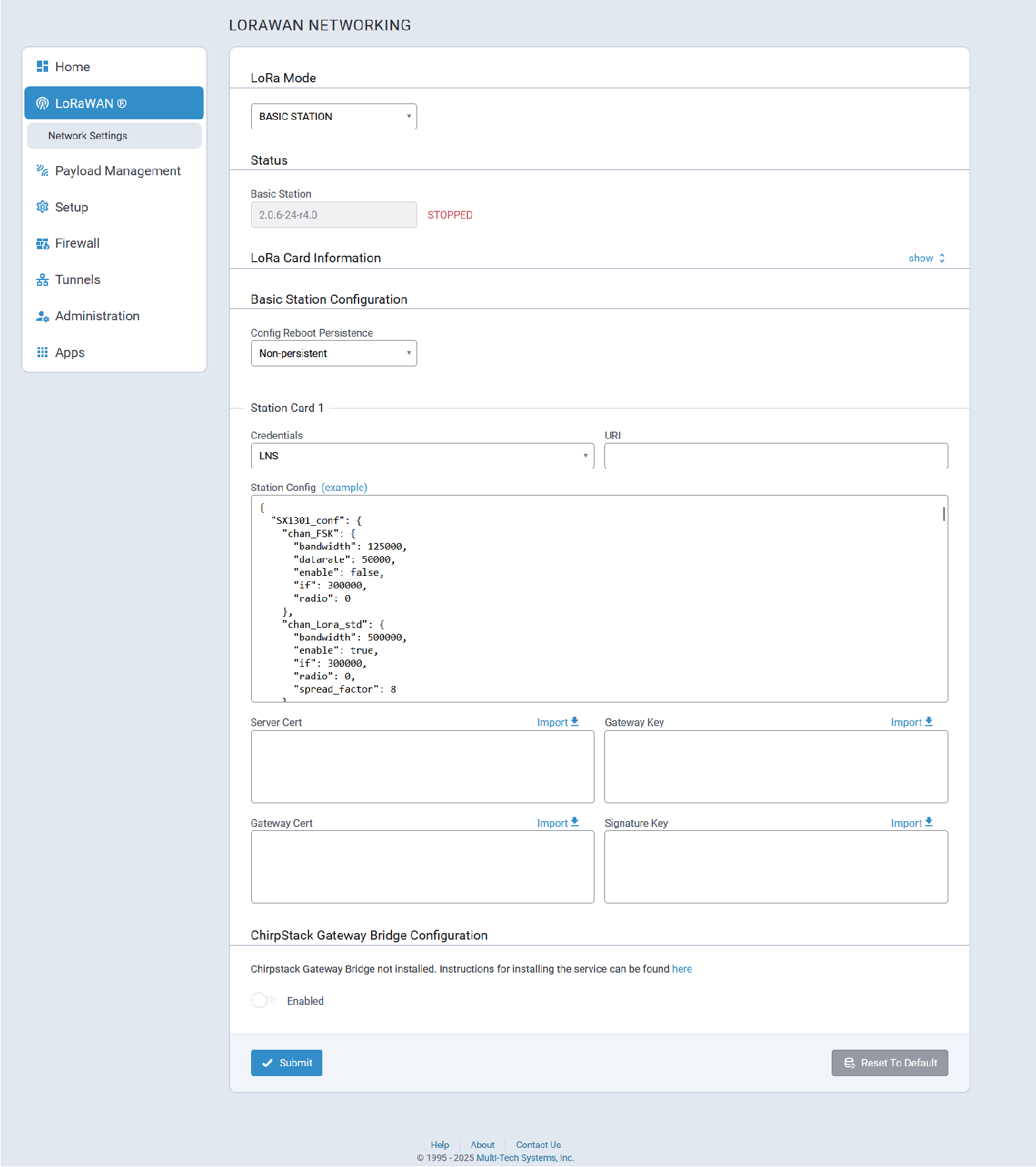
Basic Station Mode
Typical Basic Station mode configuration parameters are shown here:
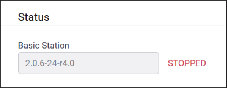
Status
LoRaWan Basic Station status information is shown here:
| Parameter | Default Value | Description |
|---|---|---|
| Basic Station | Depends on latest software version | Basic Station software version (For LoRa cards - 868 and 915 only) |
| Basic Station Status | If configured properly, RUNNING | Basic Station status. Values include RUNNING, RESTARTED, or DISABLED. |
LoRa Card Information
Typical LoRa Card parameter information is provided here:
| Parameter | Default Value | Description |
|---|---|---|
| Gateway EUI | N/A | Gateway ID of Conduit, queried from the LoRa card (if present). |
| Frequency Band | Depends on LoRa card | Frequency band set based on the installed LoRa peripheral. |
| FPGA Version | Depends on LoRa card | FPGA firmware version of the installed LoRa card. |
| Upgrade FPGA | N/A | Click on link to upgrade FPGA firmware on the LoRa card, if a later version is available. |
| Current Version | Depends on LoRa Card | Current FPGA firmware version of the installed LoRa card. |
| Upgrade Version | Depends on LoRa Card | Upgrade version of FPGA firmware if available. If this field displays an upgrade version, click Start to upgrade the firmware. If this field displays No Options Available, then you already have the latest version and you can click Cancel. |
Basic Station Configuration
Typical Base Station Configuration parameters are shown here:
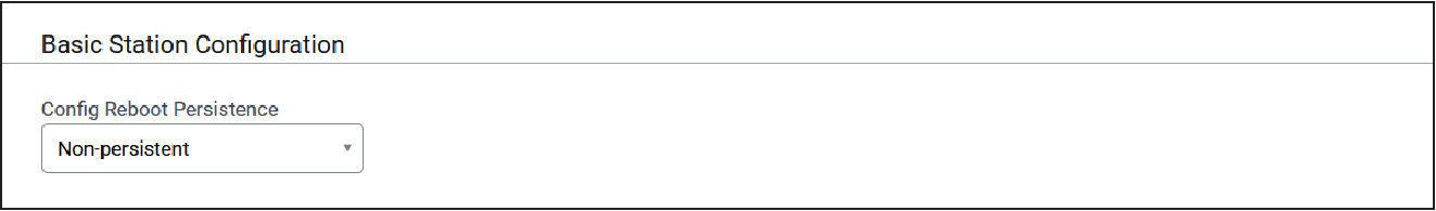
| Parameter | Default Value | Description |
|---|---|---|
| Config Reboot Persistence | TBD | TBD |
Station Card
Typical Station Card configuration parameters are shown here:
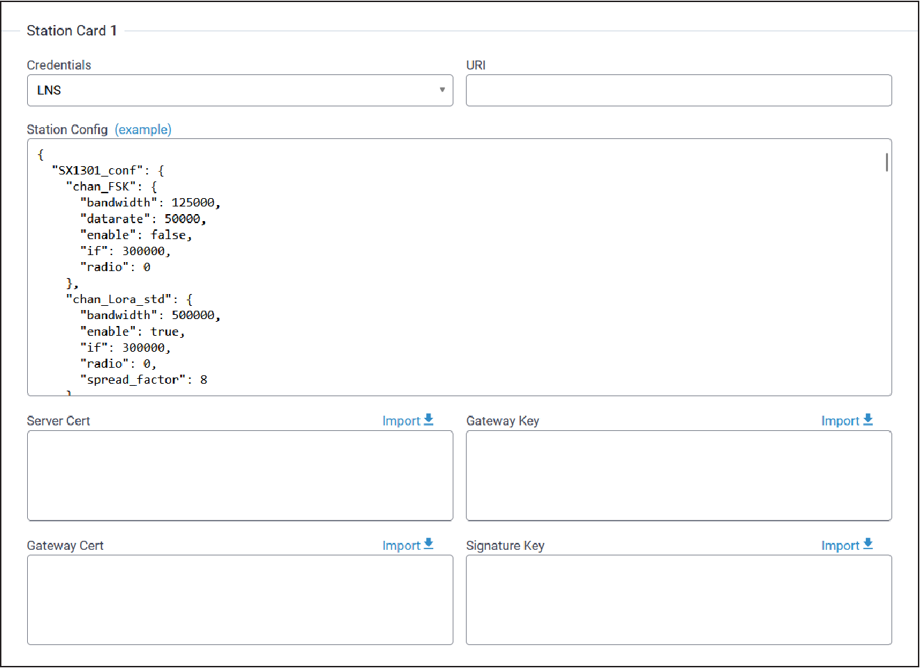
| Parameter | Default Value | Description | |
|---|---|---|---|
| Credentials | LNS | Choose connection method to reach network server. Select from LNS or CUPS. | |
| URI | N/A | URI to connect to CUPS or LNS server. | |
| Station Configuration | Example | Station configuration for the gateway. See included example file. | |
| Server Cert | N/A | Server certificate used to authenticate CUPS or LNS server. | |
| Gateway Key | N/A | Client key used by server to authenticate gateway. | |
| Gateway Cert | N/A | Client certificate used by server to authenticate gateway. | |
| Signature Key | N/A | Signature key used by server to authenticate gateway. |
Key Management
For Local Network Settings, after you change these fields, click Submit. Then, click Save and Apply to save your changes.
Join Server
Choose the location of your join server.
| Parameter | Default Value | Description |
|---|---|---|
| Location | Cloud Key Store | Choose Remote or local Join Server to handle OTA join requests. Select from drop-down either Cloud Key Store or Local Keys. |
Add End Device Credentials
In order to use this section, you must choose Local Keys under Join Server and click on Add New to add new end-device credentials.
| Parameter | Default Value | Description |
|---|---|---|
| Dev EUI | N/A | Enter Device EUI. |
| App EUI | N/A | Enter App EUI. |
| App Key | N/A | Enter App Key. |
| Class | A | Select Device Class from A, B, or C. |
| Device Profile | N/A | Select Device Profile from drop-down. |
| Network Profile | N/A | Select Network Profile from drop-down. |
Settings (for Cloud Key Store)
| Parameter | Default Value | Description |
|---|---|---|
| Join Server URL | https://join.devicehq.com/api/m1/joinreq | Join Server address (You can verify the join server by clicking the Test button.) |
| Enable Lens API | Disabled (Unchecked) | Enable Lens API to use Lens portal to manage LoRaWAN network. |
| Lens API URL | https://lens.devicehq.com/api/ | Lens API URL. |
| Check-In Interval | 3600 | Number of seconds between device check-in to Lens cloud. |
| Gateway EUI | N/A | Gateway EUI (Extended Unique Identifier) |
| UUID | N/A | Universally Unique Identifier (128-bit ID) |
| Serial Number | N/A | Device serial number |
Messages (available using Cloud Key Store)
| Parameter | Default Value | Description |
|---|---|---|
| Network Stats | Enabled | Send periodic network stats to Lens servers. |
| Packet Metadata | Enabled | Send metadata on uplink and downlink packets to Lens servers. |
| Packet data | Disabled | Send data from uplink and downlink packets to Lens servers. |
| Gateway Stats | Enabled | Send periodic gateway stats to Lens servers. |
| Local Join Metadata | Enabled | Send periodic gateway stats to Lens servers. |
| DeviceHQ | Enabled | Allows Lens to control DeviceHQ connectivity settings (optional). |
Gateway Info (available using Cloud Key Store)
| Parameter | Default Value | Description |
|---|---|---|
| Gateway EUI | N/A | Gateway EUI (Extended Unique Identifier) |
| UUID | N/A | Universally Unique Identifier (128-bit ID) |
| Serial Number | N/A | Device serial number |
Traffic Manager (available using Cloud Key Store)
| Parameter | Default Value | Description |
|---|---|---|
| JoinEUI Filter | N/A | Applied to received Join Requests to limit the number of messages sent to Join Server from unwanted devices (Read-only display of logic downloaded from Lens settings). |
| DevEUI Filter | N/A | Applied to received Join Requests to limit the number of messages sent to the Join Server from unwanted devices (Read-only display of logic downloaded from Lens settings). |
Local Network Settings
| Parameter | Default Value | Description |
|---|---|---|
| Enabled | Checked (enabled) | Enable or disable Local Network Settings. |
| Default Device Profile | N/A | Default device profile to use for newly joined end-devices
authenticated with the Local Network Settings, AppEUI and
AppKey.
For information about LoRaWAN profiles, refer to Profiles. |
| Network ID (AppEUI) | Name | Specify Network ID format from local application network ID or App EUI. Select from drop-down: Name or EUI. |
| Name | Uses local device name | Gateway device name |
| Default Network Profile | DEFAULT-CLASS-A | Default network profile to use for newly joined end-devices
authenticated with the Local Network Settings, AppEUI and
AppKey.
For information about LoRaWAN profiles, refer to Profiles. |
| Network Key (AppKey) | Passphrase | Choose Network Key from Passphrase or Key. |
| Passphrase | N/A | Enter Passphrase if used. |
| Key | N/A | Enter Key if used (128-bit hexadecimal value). |
Spectral Scan Configuration
| Parameter | Default Value | Description |
|---|---|---|
| Enabled | Unchecked (disabled) | Enable or disable Spectral Scan. |
| Scan Settings | ||
| Samples | 10000 | Total number of RSSI points. |
| Bandwidth | 250 | Channel bandwidth in kHz. |
| Step | 100000 | Frequency step between start and stop (in Hz). |
| Offset | 0 | Offset in dB to be applied to resultant data |
| Floor | -120 | Threshold in dB below which results are ignored. |
| Scheduling | ||
| Start | 9:00 | Start time for scans in UTC time. Leave blank to use current time. |
| Interval | 1 | Time period, in minutes, between run sets. |
| Stop | Never | Stop criteria for scans. Valid values are:
|
| Duration | 1 | Duration, in hours, of continuous scans.
When Stop=After
Duration, configure Duration=0 to run one
single scan. |
| Scan Sets to Run | 0 | Scan limit.
This parameter is enabled when Stop=After
Number of Scans. |
| Scan Sets - First set range is required and two default ranges are provided. Others are optional up to 5 max. Each range set is independent and flexible. Enter start and stop range and click Add to add that range as an additional set. Click Remove to delete one. | ||
| Start 1 | 902100000 | Required Start frequency 1 in Hz |
| Stop 1 | 903900000 | Required Stop frequency 1 in Hz |
| Start 2 | 923000000 | Optional Start frequency 2 in Hz |
| Stop 2 | 928000000 | Optional Stop frequency 2 in Hz |
| Start 3 | N/A | Optional Start frequency 3 in Hz |
| Stop 3 | N/A | Optional Stop frequency 3 in Hz |
| Start 4 | N/A | Optional Start frequency 4 in Hz |
| Stop 4 | N/A | Optional Stop frequency 4 in Hz |
| Start 5 | N/A | Optional Start frequency 5 in Hz |
| Stop 5 | N/A | Optional Stop frequency 5 in Hz |
Gateways
This section displays all active and configured gateways. The following information displays:
| Parameter | Description |
|---|---|
| Gateway EUI | Gateway EUI (Extended Unique Identifier) |
| IP address | Gateway IP address |
| IP Port | Port used for LoRaWAN Gateway |
| Version | Protocol version of Packet Forwarder |
| Last Seen | Time of last update, Minutes or hours ago |
| Options | Additional statistics and details for Gateway option in last five minutes. Click info icon for details. |
Packets Received
| Parameter | Description |
|---|---|
| Gateway EUI | Gateway EUI (Extended Unique Identifier) |
| Channels 1 -10 | Number of packets received on this channel |
| CRC | Cyclic Redundancy Check failed |
| Adding Total | Count of packets on all channels including CRC errors |
Network Statistics
| Parameter | Description |
|---|---|
| Join Request Responses | Average Join Request Response in milliseconds: 90%, 70%, 30% |
| Join Packets | Number of Okay packets, Duplicates and MIC fails, Unknown, Late, Total |
| Transmitted Packets | Pkt (Packets) 1st Wnd (Window), Pkt 2nd Wnd, ACK Pkt, Total, Join 1st Wnd, Join 2nd Wnd, Join Dropped, Join Total |
| Received Packets | MIC Fails, Duplicates, CRC Errors, Total |
| Scheduled Packets | 1st Wnd, 2nd Wnd, Dropped, Total |
Duty Cycle Time-On-Air Available (seconds - only available for EU)
| Parameter | Description |
|---|---|
| Gateway EUI | Gateway EUI (Extended Unique Identifier) |
| Bands 0-3 | Channel bands |
Devices
This section allows users to add new end-devices. To add a new end-device:
- Go to LoRaWAN > Devices.
- Under End Devices, click Add New.
- Enter the following fields:
- Dev EUI - the end-device EUI (Extended Unique Identifier)
- Name - the name of the end-device
- Class - LoRaWAN operating class of end-device. Is communicated to network server on Join. The end-device must be configured out-of-band for operating class. A, B, or C are currently supported. (A, B, or C).
- Serial Number - Serial number of end-device
- Product ID - Product ID for end-device
- Hardware Version - Hardware version for the end-device
- Firmware Version - Firmware version for the end-device
- LoRaWAN Version - Software version for LoRaWAN server
- Click Finish.
- The new end-device displays under the End Devices list including some device details and statistics.
- To edit the device, click the pencil icon, or to delete it, click the X icon associated with that device.
- To delete all devices, click the Delete All button.
Device Sessions
The normal join process involving properly configured and registered gateways and end-devices creates sessions FOTA (Firmware Over-the-Air) automatically.
However, you can use the Device Sessions section, if you want to create a session manually, otherwise known as ABP (Activation by Personalization). The manual session includes only the gateway and end-devices. The server is not involved.
To add a new session manually:
- Go to LoRaWAN > Devices.
- Under Sessions, click Add New.
- Enter the following fields:
- Dev EUI - End-device EUI (Extended Unique Identifier)
- Dev Addr - Network device address assigned to end-device
- Class - Device Class (B or C)
- App EUI - Application EUI
- Join EUI - Join Request EUI
- Net ID - Network ID
- App Session Key - Pre-shared application session key
- Net Session Key - Derived network session key based on pre-shared application key
- Multicast Session - Select from:
- No (i.e., not a multicast session)
- Class B
- Class C
- Click Finish.
- The new session displays under the Sessions list including some device
details and statistics.
- Dev EUI - End-device EUI (Extended Unique Identifier)
- Dev Addr - Network device address assigned to end-device
- Up FCnt - Packet counter of last received packet
- Down FCnt - Packet counter of last sent packet
- Last Seen - Time of last packet received
- Joined - What is the device joined to, Cloud or local version
- Details - Additional session information (click on info icon)
- Multicast Session - Select from:
- No (i.e., not a multicast session)
- Class B
- Class C
- To edit the session, click the pencil icon, or to delete it, click the X icon associated with that session.
- To delete all sessions, click the Delete All button.
Device Groups
This page allows you to create Device Groups in order to perform mass firmware upgrade OTA and multicast messaging to all devices in that group.
The Groups table displays existing groups. Use the View, Edit, or Remove buttons to see, modify, or delete an existing group in the table.
To create a new device group:
- Go to LoRaWAN > Device Groups.
- Click the Add New button.
- The Add Group dialog box appears. Enter your desired Group Name.
- You can also enter an optional Group EUI. If you do not provide one, the system generates a Group EUI automatically.
- Select the desired end device(s) to include in your group by clicking the box next to each Device EUI.
- Click Add.
To import your device group:
- Click Import.
- Click Choose File and browse to select your desired file.
- Click Import.
To export all your device groups, click Export All.
Groups table fields
| Item | Description |
|---|---|
| Name | Device Group Name (user-defined) |
| EUI | Optional Device Group EUI (the system generates one for you if undefined) |
| Size | Number of devices in the group |
| Options | Edit and Delete options |
Profiles
When connected to the LoRaWAN server, the profiles can be downloaded from the cloud. There are two-kinds of profiles: End-Device and Network.
Make profile changes in the Lens cloud and the device updates during a periodic check-in or when end-device associated with the profile joins or rejoins the network.
See existing profiles under the End-Device Profiles and Network Profiles lists. Refer to tables for profile details. Click Refresh to update the list.
Settings provided in the device profile must reflect the default settings of the end-device when it is first joined to the network. The end-device should be in this default configuration. Any deviation between the device profile and the actual default end-device settings may result in lost downlinks to the end-device due to non-matching Rx window parameters.
To add a new device profile:
- Go to LoRaWAN > Profiles.
- Under End-Devices Profiles, click Add New.
- Configure the following parameters as required:
- Profile ID - Enter the desired profile name
- Max EIRP
- Max Duty Cycle - Select from the drop-down including DEFAULT or a range of options from 100% to 0.003%.
- MAC Version.
- RF Region - Select from the drop-down including DEFAULT, US915, AU915, AS923, KR920, EU868, IN865, and RU864.
- Region Version.
- Supports Class C (Check box to enable. If this is enabled, then you may
enter a value for the following field.)
- Timeout Class C
- Supports Class B (Check box to enable. If this is enabled, the following
fields appear and you may enter values for them.)
- Ping Slot Period
- Ping Slot Datarate
- Ping Slot Frequency
- Supports Join (check box to enable)
- Support 32 Bit FCnt (check box to enable)
End-Device Profiles (edit/add new)
| Parameter | Description |
|---|---|
| Profile ID | Profile name |
| Max EIRP | Maximum transmit power of the end-device |
| Max Duty Cycle | Maximum duty-cycle of the end-device |
| MAC Version | LoRaWAN version supported by end-device Note: MAC commands and network messages are
different for LW1_0 and LW1_1.
|
| RF Region | End-device region or channel plan |
| Region Version | Revision of Regional Parameters specification |
| Supports C | True when the end-device can use class C
mode |
| Timeout C | Time for the end-device to reply to a confirmed downlink before retransmission |
| Supports B | True when the end-device can use class B
mode |
| Timeout B | Time for the end-device to reply to a confirmed downlink before retransmission |
| Ping Slot Period | How often the end-device opens class B windows Valid value: 1 (once per second) up to 128 (once per beacon period) |
| Ping Slot Datarate | Data rate used for class B window |
| Ping Slot Frequency | Frequency used for class B window |
| Supports Join | True when the end-device supports OTA join |
| Rx1 Delay | Default delay between the end of the Tx window and the beginning of
the first Rx window Note: When Rx1 Delay is not specified, the
LoRaWAN default for the selected channel plan is
used.
|
| Rx1 DR Offset | Default data rate offset of the first Rx window Note: When Rx1 DR Offset is not specified,
the LoRaWAN default for the selected channel plan is
used.
|
| Rx2 DR Index | Default data rate of second Rx window Note: When
Rx2 DR Index is not specified, the LoRaWAN default for
the selected channel plan is used.
|
| Rx2 Frequency | Default frequency of second Rx window Note: When
Rx2 Frequency is not specified, the LoRaWAN default for
the selected channel plan is used.
|
| Preset Frequencies | Additional channels configured at the end-device |
| Supports 32 Bit FCnt | True when the end-device supports 32 bit
counters |
Network Profiles
Settings provided in the network profile reflect the settings of the end-device to be received in MAC commands after it is first joined to the network. These are the desired settings for the end-device to operate with. Any deviation between the network profile and the default end-device settings are sent to the end-device in successive MAC commands until all settings have been relayed.
To add a new network profile:
- Go to LoRaWAN > Profiles.
- Under Network Profiles, click Add New.
- Configure the following parameters as required:
- Profile ID – Enter the desired profile name
- Max Duty Cycle - Select from the drop-down including DEFAULT or a range of options from 100% to 0.003%
- Class- Select from the drop-down including A, B, or C
- Timeout Class C
- Rx1 Delay
- Rx1 DR Offset - Select from drop-down which varies with your selected channel plan.
- Rx2 DR Index - Select from drop-down which varies with your selected channel plan.
- Rx2 Frequency
- Channel Mask
- Redundacy
Network Profiles (edit/add new)
| Parameter | Description |
|---|---|
| Profile ID | Profile name |
| Max Duty Cycle | Maximum duty-cycle of the end-device |
| Class | Operating class for end-device
Valid values are:
|
| Timeout C |
Time for the end-device to reply to a confirmed downlink before retransmission |
| Rx1 Delay | Default delay between the end of the Tx window and beginning of
the first Rx window Note: When Rx1 Delay is not
specified, the LoRaWAN default for the selected channel plan
is used.
|
| Rx2 DR Index | Default data rate of the second Rx window Note: When Rx2 DR Index is not
specified, the LoRaWAN default for the selected channel plan
is used.
|
| Rx2 Frequency | Default frequency of the second Rx window Note: When Rx2 Frequency is not
specified, the LoRaWAN default for the selected channel plan
is used.
|
| Channel Mask | The bitmask to enable channels
The United States uses a
20-character bitmask structured as follows:
Australia uses a 20-character bitmask. All others use a 4-character bitmask. For example, in the EU, the
mask to enable all channels is |
| Redundancy | The number of times an unconfirmed uplink should be repeated |
Packets
This section shows three lists: transmitted, recent join requests, and recently received packets on the LoRa network. Each packet includes relevant packet details.
Packets (Transmitted)
| Parameter | Description |
|---|---|
| Device EUI | End-device EUI (Extended Unique Identifier) transmitting the uplink packet or destination of the downlink packet |
| Freq | Frequency used to transmit packet |
| Datarate | Datarate used to transmit packet |
| SNR | Signal to noise ratio of received packet |
| CRC | Cyclic redundancy check failed |
| RSSI | Received signal strength |
| Size | Size in bytes of packet |
| FCnt | MAC packet counter |
| Type | Type of packet includes these possible values:
|
| Tx/Rx Time | Time packet was sent or received |
| Details | Additional packet details Note: Click on the
Info icon to view the dialog.
|
Recent Join Requests
| Parameter | Description |
|---|---|
| Join EUI | 8-byte EUI (Extended Unique Identifier) found in the join request |
| Nonce | Join nonce provided by end-device in the Join Request |
| Elapsed | Round trip time in milliseconds for the Join Server to service the join request |
| Result | If the result of the request is valid, it displays:
Success.
If the result is an error, one of the following is
displayed:
|
Recent Rx Packets
| Parameter | Description |
|---|---|
| Time | Time packet was received |
| Freq | Frequency used to transmit packet |
| Datarate | Data rate used to transmit packet |
| CRC | Cyclic redundancy check failed |
| SNR | Signal to noise ratio of received packet |
| RSSI | Received signal strength |
| Size | Size in bytes of packet |
| Type | Type of packet includes these possible values:
|
| Data | Actual data in packet (payload) |
| Details | Additional packet details Note: Click on the
Info icon to view the dialog.
|
Downlink Queue
Downlink packets can be manually sent to an end-device.
The packet remains in the queue until sent. Once it has been transmitted/received, the packet displays under Packets.
To manually send a downlink packet:
- Go to LoRaWAN > Downlink Queue. Click on Add New.
- Configure the following information for the new Queue Item:
- Dev EUI - receiving end-device EUI (Extended Unique Identifier)
- App Port - port field set in the downlink packet
- Data Format - encoding scheme for the packet (select either Hex or Base64).
- Data - the payload (data being transmitted)
- Ack Attempts - number of allowed downlink request
ackretries - RxWindow - specify the Rx Window to use for downlink. Valid values
are:
0: no priority1: First Rx window2: Second Rx window
- Click Finish.
- The new Queue Item displays under the Downlink Queue list including
some device details and statistics.
- Dev EUI - receiving end-device EUI (Extended Unique Identifier)
- App Port - port field set in the downlink packet
- Size - total packet minus header
- Ack - number of retries to receive ACK from end-device
- RxWnd - the Rx Window to use for downlink:
0: no priority1: First Rx window2: Second Rx window
- Queued - Time packet has been added to the queue
- Details - additional statistics displayed related to the packet
- To edit the item, click the pencil icon, or to delete it, click the X icon associated with that item.
- To delete all items, click the Delete All button.
Operations
- FOTA
- Multicast Messaging
The device offers the option of FOTA using your LoRaWAN network. To use this feature, you must properly configure your LoRa network and end-devices (must be joined to the network). You may set a countdown for an immediate update or schedule the upgrade for a specific time. You can also update multiple devices on your LoRa network.
The device also offers the option of Multicast Messaging over the LoRaWAN network.
To perform FOTA:
- Go to LoRaWAN > Operations.
- Under Operations Settings, select FOTA in the Operation Type drop-down.
- Click Browse and select your Firmware Upgrade File (.bin).
- Under the Fragment Description field, enter the fragment description for the FOTA session in HEX format.
- You have the option to specify a Setup Time In by clicking Change. Setup time
specifies how long from the time scheduled before the Multicast Setup Process
begins. Under Setup Time Input from the drop-down, select either:
- Countdown to Setup from Now: Enter Number of Days plus hours, minutes and seconds in HH:MM:SS (default: 30 seconds) OR
- Specify Future Date and Time: Select your desired Date and Time.
- Otherwise, click Hide to hide Setup Time Input details. Click Change to show and modify.
- You have the option to specify a Launch Time In. Launch time specifies how
long the Multicast Process runs before starting firmware transmission. Under
Launch Time Input from drop-down, select either:
- Countdown to Launch from Setup: Enter Number of Days plus hours, minutes and seconds in HH:MM:SS (default: 90 seconds) OR
- Specify Future Date and Time: Select your desired Date and Time.
- Choose the desired Target End-Devices to receive the upgrade. Select either a previously-saved End-Device Group or Individual Devices from the drop-down on the right. Check the box near your desired device or group to designate it for upgrade. You can also check Select/Deselect All box to select or deselect all groups in the list.
- Click the Settings tab, if you wish to change the defaults for the following
FOTA parameters
- Delete Successful Logs (default: checked)
- Multicast Group ID
- Number of Parity Fragments per Session (default: 100)
- Sleep Delay between Setup Messages (default: 1000 microseconds)
- Sleep Delay between Data Fragments (default: 1500 microseconds)
- Sleep Delay between Parity Fragments (default: 3000 microseconds)
- Maximum Packet Size
- After configuring FOTA, click Schedule to finalize your FOTA update.
- Once the scheduled upgrade is submitted, you can track its progress through the Progress tab. A progress bar appears at the top of the page. The progress bar shows the transfer of the file from the PC to the device. Once completed, the page switches to the Progress tab. The job displays in either Scheduled, Active, or Completed Jobs lists depending on the job phase and timing.
To perform the Multicast Messaging:
- Go to LoRaWAN > Operations.
- Under Operations Settings, select Message in the Operation Type drop-down.
- Select from either Textbox or File under Payload Source.
- Select from either Hexadecimal or Base64 under Payload Format.
- Enter the message contents under Payload.
- Enter the Port from a range of 1-220 (default: 1).
- Under Transmission Setup, you have the option to specify a Setup Time
Input by clicking Change. Setup time specifies how long from the time
scheduled before the Multicast Setup Process begins. Expand the Setup Time
Input drop-down and select from the following options:
- Countdown to Setup from Now: Enter Number of Days plus hours, minutes, and seconds formatted as HH:MM:SS (default value: 30 seconds)
- Specify Future Date and Time: Configure the desired Date and Time.
- Otherwise, click Hide to hide Setup Time Input details. Click Change to show and modify.
- You have the option to specify a Launch Time Input. Launch time specifies how
long the Multicast Process runs before starting message transmission. Expand the
Launch Time Input drop-down and select from the following options:
- Countdown to Launch from Setup: Enter Number of Days plus hours, minutes, and seconds formatted as HH:MM:SS (default value: 90 seconds)
- Specify Future Date and Time: Configure the desired Date and Time.
- Choose the desired Target End-Devices to receive the message. Select either a previously-saved End-Device Group or Individual Devices from the drop-down on the right. Check the box near the desired device or group to designate it to receive the message. You can also check Select/Deselect All box to select or deselect all groups in the list.
- Click the Settings tab to change the defaults for the following message
parameters:
- Delete Successful Logs (default value: checked)
- Multicast Group ID
- Sleep Delay between Setup Messages (default value: 1000 microseconds)
- Sleep Delay between Data Fragments (default value: 1500 microseconds)
- Maximum Packet Size
Note: The following parameters are constants for Multicast Messaging and cannot be modified:- Number of Parity Fragments per Session: value is 100
- Sleep Delay between Parity Fragments value is 3000 microseconds
- After configuring Multicast Messaging, click Schedule to schedule your message.
- Once the message is submitted, you can track its progress through the Progress tab. A progress bar appears at the top of the page. The progress bar shows the transfer of the message from the PC to the device. Once completed, the page switches to the Progress tab. The job displays in either Scheduled, Active, or Completed Jobs lists depending on the job phase and timing.
Payload Management
This chapter provides an overview about how to configure Payload Management settings such as BACnet Devices, sensors, and BACnet objects to receive BACnet data from LoRa sensors.
A typical application is illustrated here:
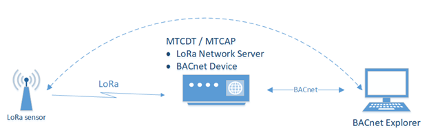
To get data from the LoRa sensor through mPower:
- Verify the device has the BACnet license. BACnet payload management requires a
license which is installed on your mPower device when it ships from the factory. If
the Payload Management pages are not available, contact your account manager for a
license.Note: For information about adding a license, refer to Licensing.
- Configure the following Network Settings:
- Go to Network Settings > Network Server.
- Set LoRa Mode to Network Server.
- Set the Channel Plan for your region.
- Make sure the Packer Forwarder and the Network Server are running.
- Key Management settings:
- Set the Join Server to Local Join Server.
- Configure Local Network Setting.
- Configure Local Network Setting.
- Go to Network Settings > Network Server.
- Set up and connect the sensor.Note: This process is dependent upon the specific sensor being used. Refer to the sensor manufacturer's documentation for further information.
- Open the LoRaWAN > Packets page. If the LoRaWAN network and sensor are configured properly, a Join Request from the sensor appears in the Recent Join Requests pane with the Success result. You will see Packets sent by the sensor in the Packets pane.
- Click Refresh to update the data on the page.
- Go to the LoRaWAN > Devices page. A new entry with the sensor Device EUI has been added to the End Devices and Sessions panes.
- Configure BACnet.Note: For complete information refer to BACnet Configuration.
- Add sensors.Note: For complete information, refer to Add Sensor.
- Add/create BACnet objects.Note: For complete information, refer to Add a BACnet Object.
- Configure a BACnet Explorer to get sensor data via BACnet.Note: This process is dependent upon the specific BACnet Explorer is being used. Refer to the software developer's documentation for further information.
BACnet Configuration
The BACnet Configuration page is illustrated here:
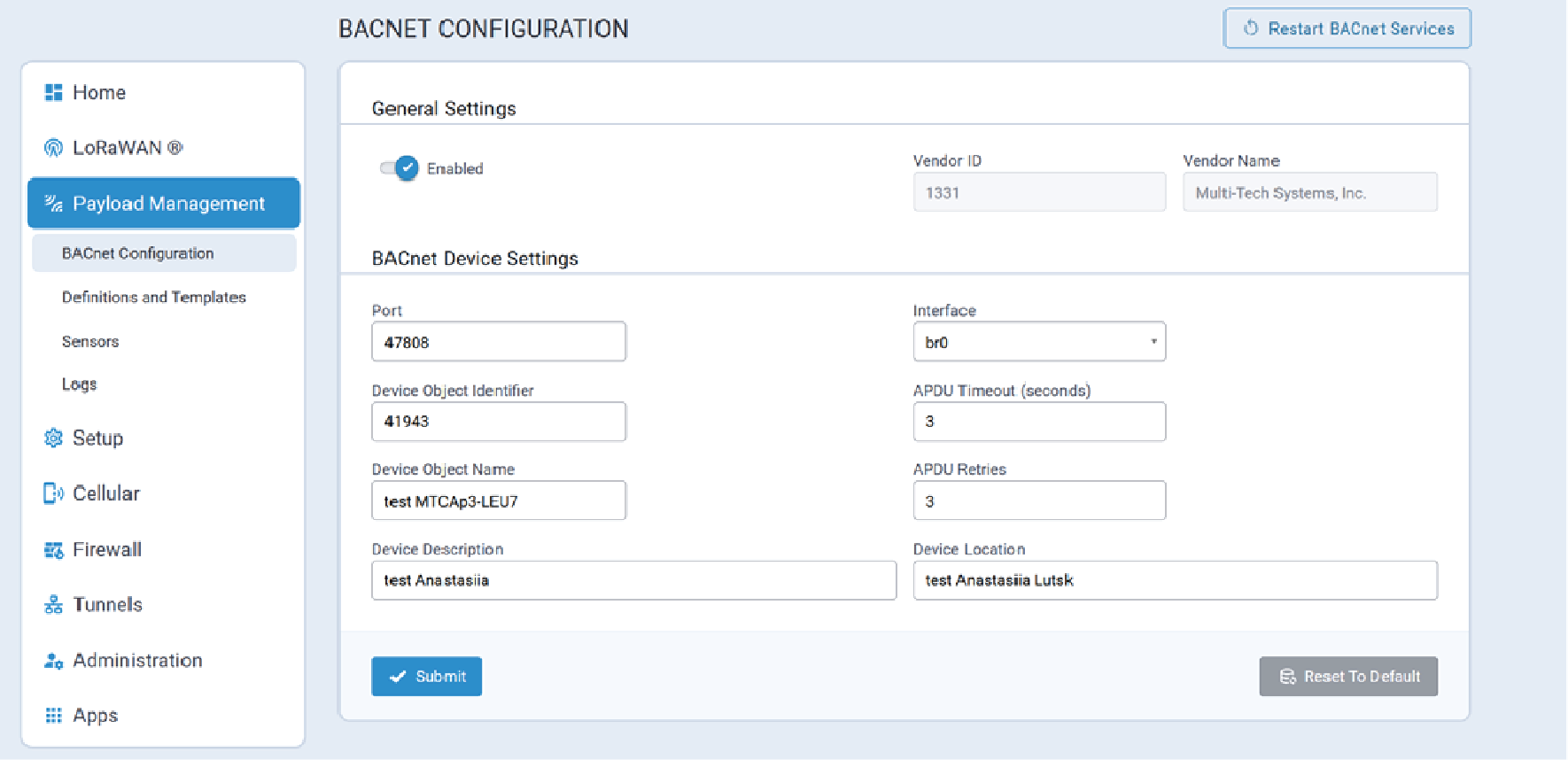
Configuration Parameters
BACnet configuration parameters are described below.
| Parameter | Valid Values | Description |
|---|---|---|
| Enabled | Valid values are:
|
Enables/disables BACnet operation. |
| Vendor ID | ||
| Vendor Name |
| Parameter | Valid Values | Description |
|---|---|---|
| Port | Numeric value from 1 to 65535, inclusive. | |
| Interface | ||
| Device Object Identifier | Numeric value from 1 to 4194302, inclusive. | |
| APDU Timeout (seconds) | Numeric value from 1 to 65, inclusive. | |
| Device Object Name | Character string. Maximum length: 128 characters |
|
| APDU Retries | Numeric value from 1 to 255, inclusive. Default value: 3 |
|
| Device Description | Optional. Character string.Maximum length: 128 characters |
|
| Device Location | Optional. Character string.Maximum length: 128 characters |
Restart BACnet Services
- Click on the button at the top of the configuration page
- Selecting the Restart BACnet Services option included on the Commands
Menu:Note: The Restart BACnet Services command is available from the Command menu only when there is a valid Payload Management license.
 button at the top of the configuration page
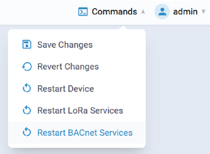
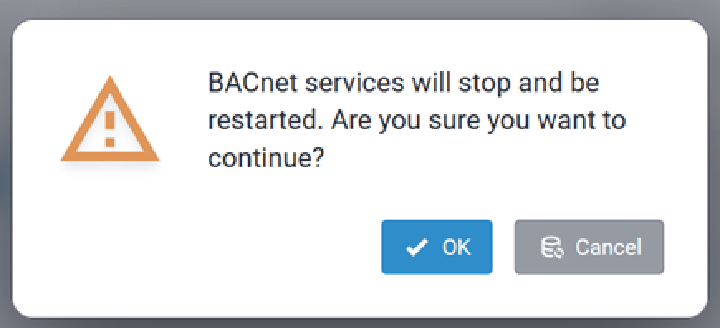
Click OK to continue.
Once the service has successfully restarted, the following message is displayed:

If BACnet services are not running when a restart is initiated, the following error message is returned:

Definitions and Templates
The Definitions and Templates page lists information for all sensors that have been defined in the Conduit® AP 300.
Sensor Definitions
A Sensor Definition is a JSON file with a corresponding sensor decoder file.
- Current sensor definitions
- Default sensor definitions
- Custom sensor definitions
- Imported sensor definitions
The Sensor Definitions tab is illustrated here:
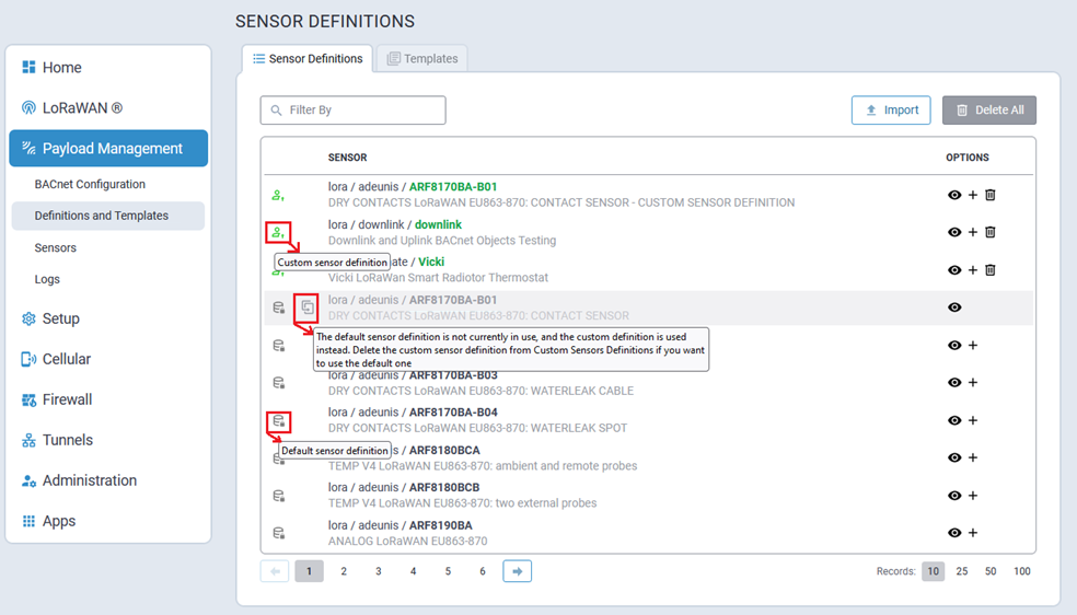
- identifies default sensor definitions
- identifies custom sensor definitions
-
 identifies a custom sensor definition that is currently being overwritten by a custom sensor definition. When this is the case, as illustrated above, a tool tip is displayed when hovering the cursor over this icon.
Note: The Add Sensor control (+) will not be shown for these sensor definitions.
identifies a custom sensor definition that is currently being overwritten by a custom sensor definition. When this is the case, as illustrated above, a tool tip is displayed when hovering the cursor over this icon.
Note: The Add Sensor control (+) will not be shown for these sensor definitions.
| Icon | Option Information |
|---|---|
| View detailed sensor definition information. | |
| + | Add Sensor control to the respective sensor definition. |
| Delete the specified sensor control. |
 button and, when prompted,
confirm deletion.
button and, when prompted,
confirm deletion.Filter the Sensor Definition List
To filter the Sensor Definition list, enter the desired filter term in the Filter By field.
- Source
- Manufacturer
- Type
- Description
Import Sensor Definitions
Importing custom sensor definitions is achieved by uploading a properly formatted Sensor Definition JSON file.
The Sensor Definition file describes the sensor data structure and corresponding sensor decoder that declares the decode Uplink function.
- Description (optional)
- Properties (required)
- Decoder (required)
Example Sensor Definition JSON File Structure
{
    "description" : "Optional description goes here",

    "properties" : {
         "DeviceID"             : {"type" :"string", "size" : 16},
         "DeviceStatus"         : {"type" : "uint8"},
         "BatteryVoltage"       : {"type" : "uint16", "units" : "amp"},
         "CounterA"             : {"type" : "uint16"},
         "CounterB"             : {"type" : "uint16"},
         "SensorStatus"         : {"type" : "uint8"},
         "TotalCounterA"        : {"type" : "uint16"},
         "TotalCounterB"        : {"type" : "uint16"},
         "PayloadCounter"       : {"type" : "uint8"}
         },

    "decoder": "SampleDecoder.js"

  }
To import a custom sensor file, click on the  button. The Details pop-up dialog is
displayed:
button. The Details pop-up dialog is
displayed:
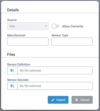
| Parameter | Required/Optional | Value |
|---|---|---|
| Manufacturer | Required | Case sensitive character string Maximum length: 15 characters Must start with a letter and include only alphanumeric characters, hyphens, and underscores. |
| Sensor Type | Required | Case sensitive character string Maximum length: 32 characters Must start with a letter and include only alphanumeric characters, hyphens, and underscores. |
| Allow Overwrite | Optional | When importing a variation of an existing sensor type, enable this field to use the new sensor definition file. |
| Sensor Definition | Required | Path to the Sensor Definition JSON file to be imported |
| Sensor Decoder | Required | Path to the Sensor Decoder file to be imported. |
Download Sensor Definitions
You can download both default (pre-installed) and custom sensor definitions and decoders that are available in the system. This allows you to back up existing configurations, review files offline, reuse them in other environments, or create custom versions of predefined sensors.
To download a sensor definition and decoder:
-
Locate the sensor in the list.
-
Click the Download icon in the Options column.
-
The system downloads a ZIP file containing the sensor definition and decoder files.
The downloaded ZIP archive always includes the matched pair of files, ensuring the sensor definition and its corresponding decoder remain synchronized.
Edit Sensor Definitions and Decoders
You can edit sensor definitions and decoders that you have imported into the system directly in the Web UI. The Web UI provides a guided, visual workflow for editing, testing, and synchronization.
When the Editor window is open, the system disables the automatic session timeout. This prevents users from being logged out unexpectedly while working in the editor.
- Sensor Definitions tab, click the Edit icon in the Options column.
- The Editor window opens.
- JS Decoder panel
- Uplink Test panel
- Downlink Test panel
- Definition panel
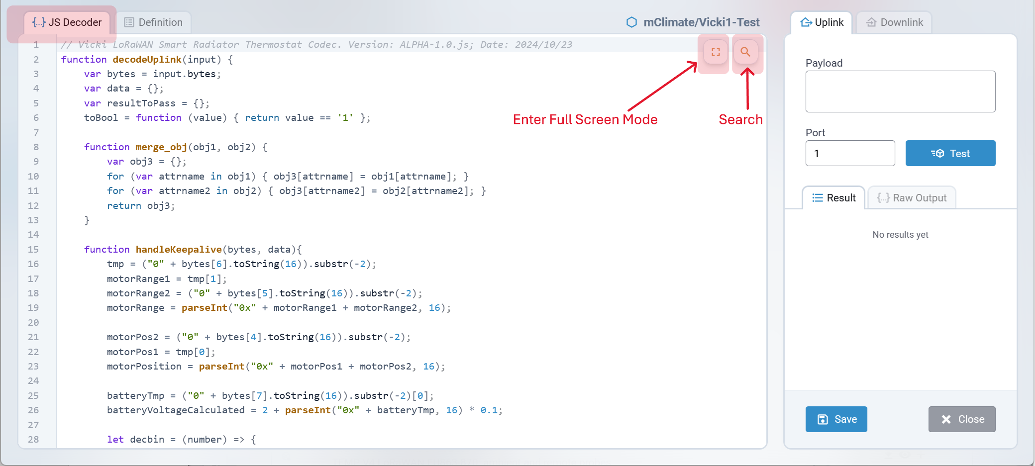
JS Decoder Pane
The JS Decoder pane is used to edit the JavaScript code for sensor decoders. It supports syntax highlighting, which automatically applies colors and styles to functions, variables, keywords, and other language elements to improve code readability and make debugging easier.
The editor does not enforce code validation or restrictions. You can edit and save any content, including incomplete or experimental code.
The JS Decoder pane has Search and Full Screen Mode options.
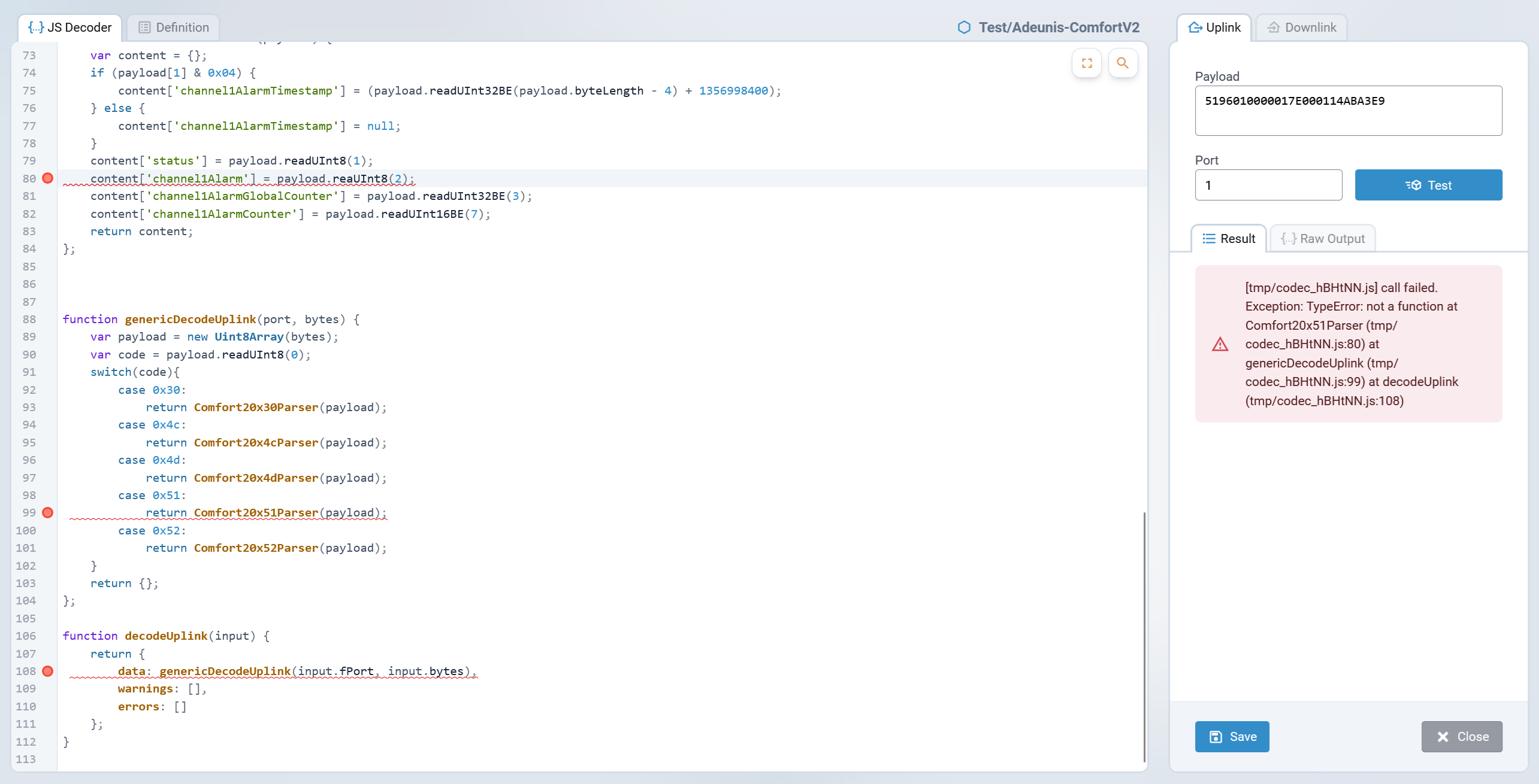
Uplink Test Pane
The Uplink test pane allows you to decode payloads using the sensor decoder and verify that the decoded output matches the expected values.
To test an uplink payload:
-
Enter a valid payload in the Payload field.
-
The Port field is set to
1by default and accepts any value from1to65535. Change the port if the decoder requires a specific port for decoding. -
Click Test.
If the decoder fails to decode the payload, the Editor displays an error message and highlights the corresponding issue in the JS Decoder pane.
When the decoder decodes the payload successfully, the results show a list of properties with their corresponding types and decoded values. These results are displayed in two read-only views:
-
Result tab: Table view of decoded properties.
-
Raw Output tab: JSON view of the decoded data.
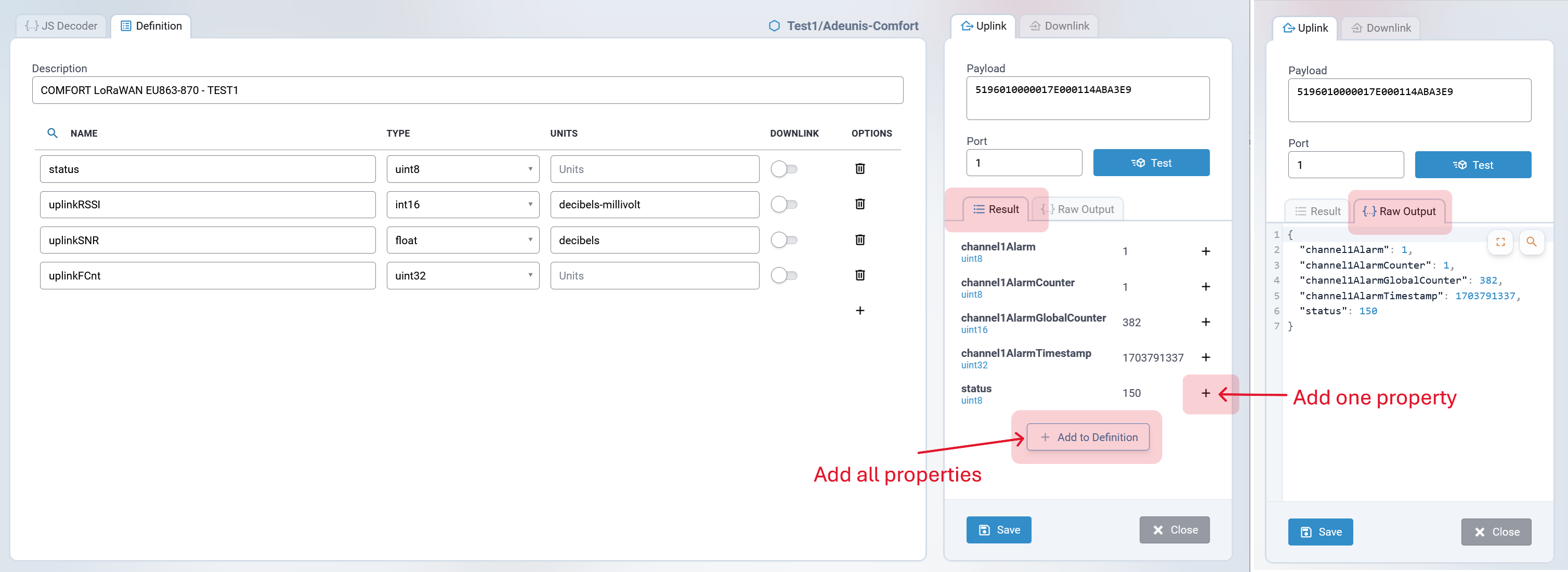
- Click + Add to Definition to add all properties.
- Click the Add (+) icon next to a specific property to add it individually.
Any properties added from the Uplink test pane are automatically highlighted in the Definition pane, making it easy to track newly added fields.
Downlink Test Pane
The Downlink pane allows you to test how the sensor decoder encodes downlink messages and to view the command that will be sent to the sensor.
Use this pane to verify that the encoded result matches the expected output. If the result is correct, you can add the downlink property directly to the sensor definition.
To add a downlink property:
-
Click + Add to Definition.
-
The Definition tab opens automatically.
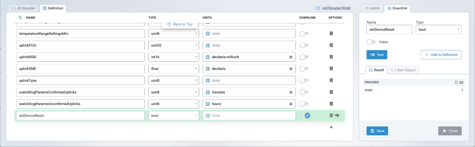
A new downlink property is added to the end of the property list using the Name and Type specified in the Downlink Test pane.
This workflow ensures that tested downlink commands are accurately reflected in the sensor definition.
Adding Uplink and Downlink Properties That Already Exist in the Sensor Definition
When you add a property from the Test Results pane that already exists in the sensor definition, the Editor applies the following rules:
-
The Editor does not create a duplicate property. If a property with the same name already exists, it highlights the existing property in the Definition pane so you can easily locate it.
-
The Editor does not change the Units value of the existing property.
-
The Editor does not update the property type for existing downlink properties.
- The Editor does not update the property type for existing uplink
properties when the type is set to
stringorbool.
The Editor updates the property type for uplink properties only when the type retrieved during decoding has a higher priority than the type defined in the sensor definition. The following list shows the supported types ordered by priority, from lowest to highest:
-
int8 -
uint8 -
int16 -
uint16 -
int32 -
uint32 -
float
Examples:
-
If the existing type is
int8and the type retrieved during testing isuint8, the Editor updates the property type touint8when adding it from the Test Results pane. -
If the existing type is
uint16and the type retrieved during testing isint32, the Editor updates the property type toint32when adding it from the Test Results pane. -
If the existing type is
int16and the type retrieved during testing isint8, the Editor does not change the property type when adding it from the Test Results pane. -
If the existing type is
bool, the Editor does not change the property type when adding it from the Test Results pane. -
If the existing type is
string, the Editor does not change the property type when adding it from the Test Results pane.
This behavior ensures that your sensor definitions remain stable while still allowing more accurate data types to be applied when better information becomes available during testing.
Definition Pane
The Definition pane allows you to view, add, edit, and delete sensor properties in a sensor definition.
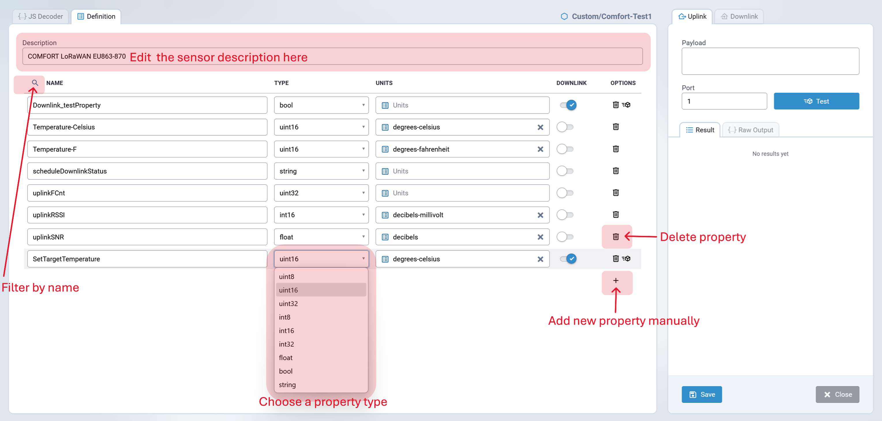
To manually add a new property, click the Add (+) icon at the bottom of the list and complete the following fields:
-
Name (required): Accepts alphanumeric characters (A–Z, 0–9), hyphens (-), and underscores (_). Maximum length is 128 characters.
-
Type (required): Select one of the following predefined data types:
-
uint8
-
uint16
-
uint32
-
int8
-
int16
-
int32
-
float
-
bool
-
string
-
-
Units (optional): Empty by default. Accepts alphanumeric characters (A–Z, 0–9), hyphens (-), and underscores (_). Maximum length is 128 characters.
Click the list icon in the Units field to open the list of BACnet-supported engineering units. Double-click a unit to insert it, or enter a value manually.
-
Data Flow Direction: Select Uplink (default) or Downlink.
The Editor does not perform validation on entered properties and does not limit the number of properties in a sensor definition. It also allows duplicate properties (same name, type, unit, and data flow direction) and allows all properties to be deleted, including saving a sensor definition with no properties.
Automatically Managed Properties
The Editor automatically manages the following properties:
-
uplinkRSSI
-
uplinkSNR
-
uplinkFCnt
-
scheduleDownlinkStatus
The properties uplinkRSSI, uplinkSNR, and uplinkFCnt must always be present in the sensor definition.
If the sensor definition contains at least one downlink property, scheduleDownlinkStatus must also be present.
When a sensor definition is opened, the Editor automatically creates any missing required properties:
-
uplinkRSSI
-
uplinkSNR
-
uplinkFCnt
-
scheduleDownlinkStatus
Behavior of these properties:
-
If you rename or delete one of these properties and save the definition, the Editor recreates it the next time the definition is opened.
-
If you change the Type, Units, or Data Flow Direction of one of these properties, the Editor preserves your changes and does not overwrite them.
-
uplinkRSSI, uplinkSNR, and uplinkFCnt are mandatory metrics used to assess the quality and reliability of the LoRaWAN connection. They are generated by the LoRaWAN gateway or network server and added automatically to the sensor data. Including them in every sensor definition allows the system to display both BACnet data and LoRaWAN link health together.
-
scheduleDownlinkStatus is required for sensors that support downlink communication. It tracks whether a downlink command has been scheduled, confirmed, or rejected by the device, which is essential for reliable two-way communication.
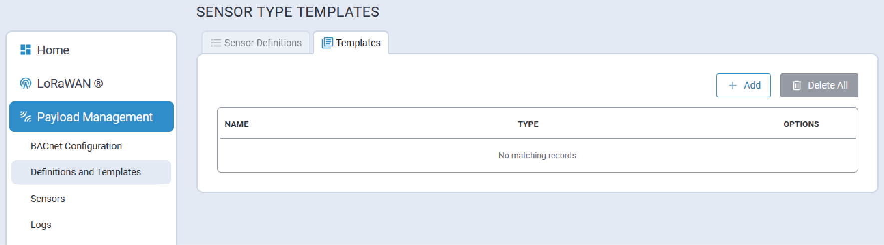
Templates Tab
The Templates tab lists available user-defined Sensor Type Templates.
- Local Join Server (Local End-Device Credentials)
- Managed Sensors list
Additionally, Sensor Type Templates can be used to add the same set of BACnet Objects for each sensor.
Add a Sensor Type Template
By default, there are no pre-defined templates provided. Users must add and configure their own templates in order to utilize templates.
- On the Sensor Type Templates page, click the + Add button. The Add
Sensor Type Template tab is displayed:
- Configure the following parameters for the new template:
Parameter Required/Optional Value General Configuration Name Required Character string Sensor Definition Required Sensor definition to which the template applies.
Select the desired definition from the pull-down list.
LoRaWAN Device Details Class Required The LoRaWAN operating class of the end-device. This is transmitted to the network server on Join. The end-device must be configured out-of-band for operating class.
Valid values are:- A
- B
- C
Device Profile Optional Network Profile Optional BACnet Objects Property N/A Once a Sensor Definition has been selected, the system automatically adds all properties with a corresponding default Object Type. Refer to Supported BACnet Object Types for complete information.
If a different Sensor Definition is selected, this list will automatically be updated to reflect the new selection.
Object N/A The system automatically generates the BACnet Object Name.
Format:
{PropertyName} - {BACnet_Object_Type_abbreviation} - Click Submit.
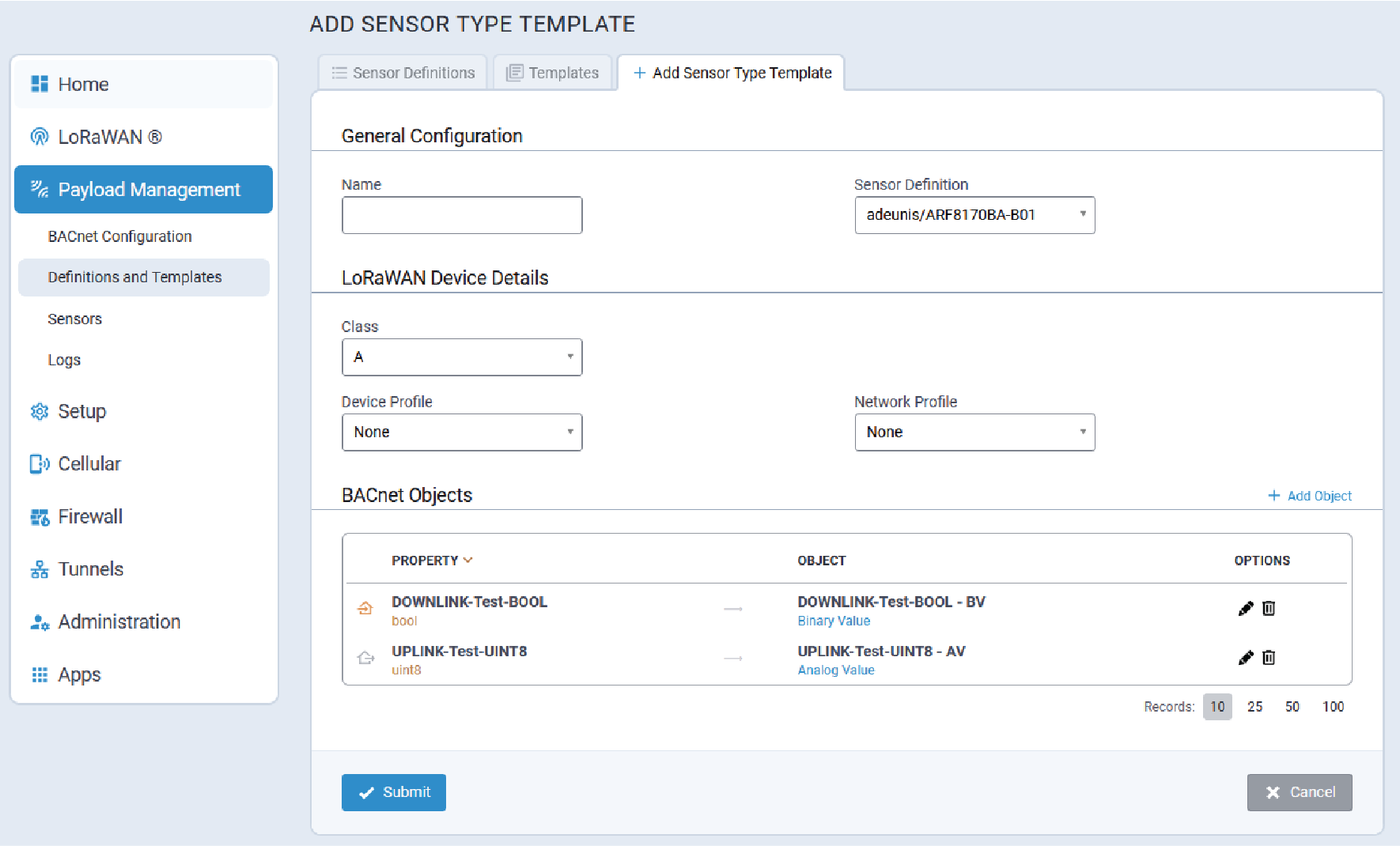
Add a BACnet Object to a Template
To add a BACnet Object to a Sensor Type template, click on the + Add Object link above the list of BACnet objects.
The Add BACnet Object dialog is displayed:
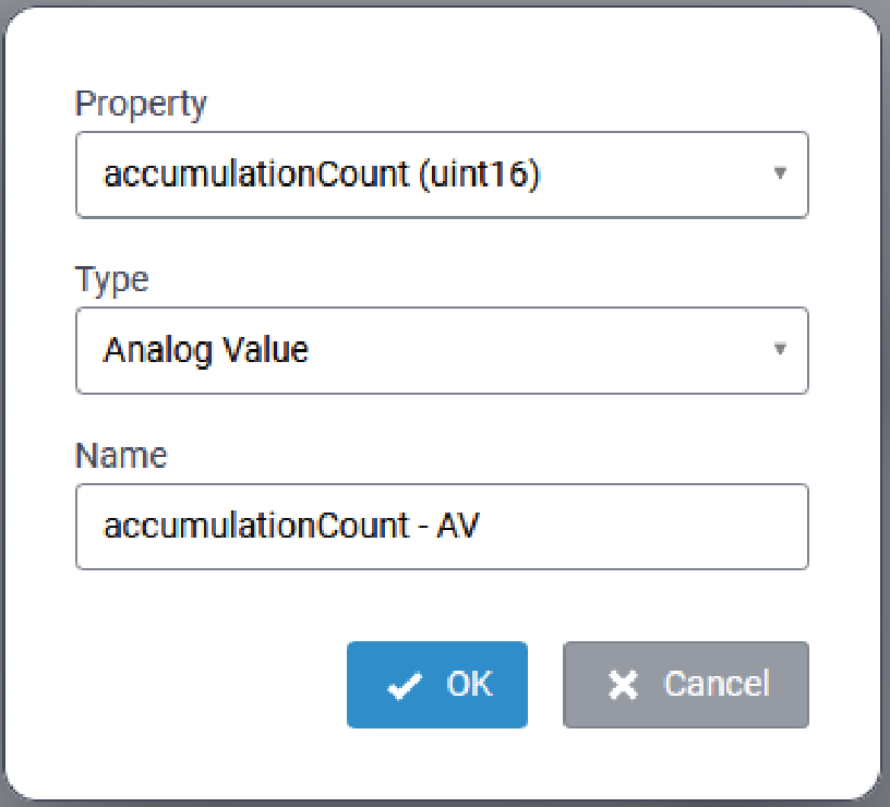
Configure the following parameters:
| Parameter | Required/Optional | Value |
|---|---|---|
| Property | Required | Select the desired Property from the pull-down list. |
| Type | Required | Select the desired Type from the pull-down list. Refer to Supported BACnet Object Types for complete information. |
| Name | Required |
Format: Note: The resulting BACnet Object Name will
include the last four digits of the sensor Device EUI.
|
Once configured, click OK to save and add the object.
Edit a BACnet Object in a Template
BACnet Objects that are automatically added to a template may be edited. To edit a BACnet
object, click the ![]() associated with the object to be edited. The
Edit BACnet Object dialog is displayed:
associated with the object to be edited. The
Edit BACnet Object dialog is displayed:
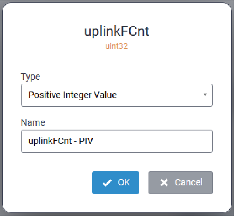
Update the Type and/or Name parameters as required, and click OK to save the changes.
Delete a BACnet Object from a Template
To delete a BACnet object from a template, click the ![]() associated with the object to be deleted. When
prompted, confirm the deletion.
associated with the object to be deleted. When
prompted, confirm the deletion.
Sensors
- Sensors
- BACnet Objects
Sensors Tab
The Sensors tab displays a list of all manages sensors, similar to that shown here:
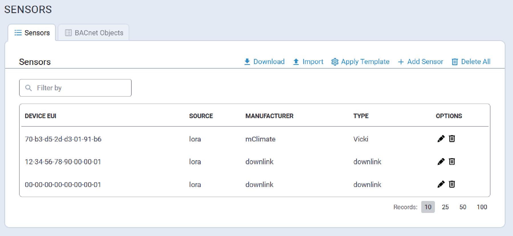
Filter Sensors List
To filter the Sensors list, enter the desired filter term in the Filter By field.
- Source
- Manufacturer
- Type
- Description
View Sensor Details
To view sensor details for a sensor, on the Sensors page click the ![]() associated with the desired sensor. The
Sensor Details page is displayed:
associated with the desired sensor. The
Sensor Details page is displayed:
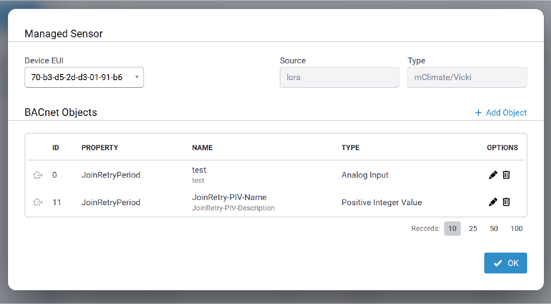
Add Sensor
Perform the following procedure to add a managed sensor:
- On the Sensors tab, click the + Add Sensor link at the top of the page.
- Enter the Device EUI in the format
XX-XX-XX-XX-XX-XX-XX-XX. - Select the sensor Manufacturer from the drop-down list.
- Select the sensor type from the Type drop-down list. These options depend on the Manufacturer selected in the previous step.
- Click Finish to add the sensor.
Apply Template
The use of Sensor Type templates streamlines the addition of LoRaWAN devices to the list of managed sensors.
- Local End-Device credentials are added. Note the following:
- Credentials are added only if the Local Join Server is enabled.
- Local End-Devices are not added, and a warning message is displayed,
if:
- The Local Join Server is disabled
- There is at least one sensor with DevEUI already present in the Local End-Devices list.
Note: Refer to Key Management for additional information. - Sensors are added to the Sensors list using the sensor definition specified by the selected
Sensor Type Template.
- If one or more sensors is being added with a DevEUI that is already in the sensors list, the system will display an error message and stop adding sensors. The user can delete the duplicate sensor and try again.
- BACnet Objects are added for each sensor on the list.
A typical Apply Template tab is shown here:
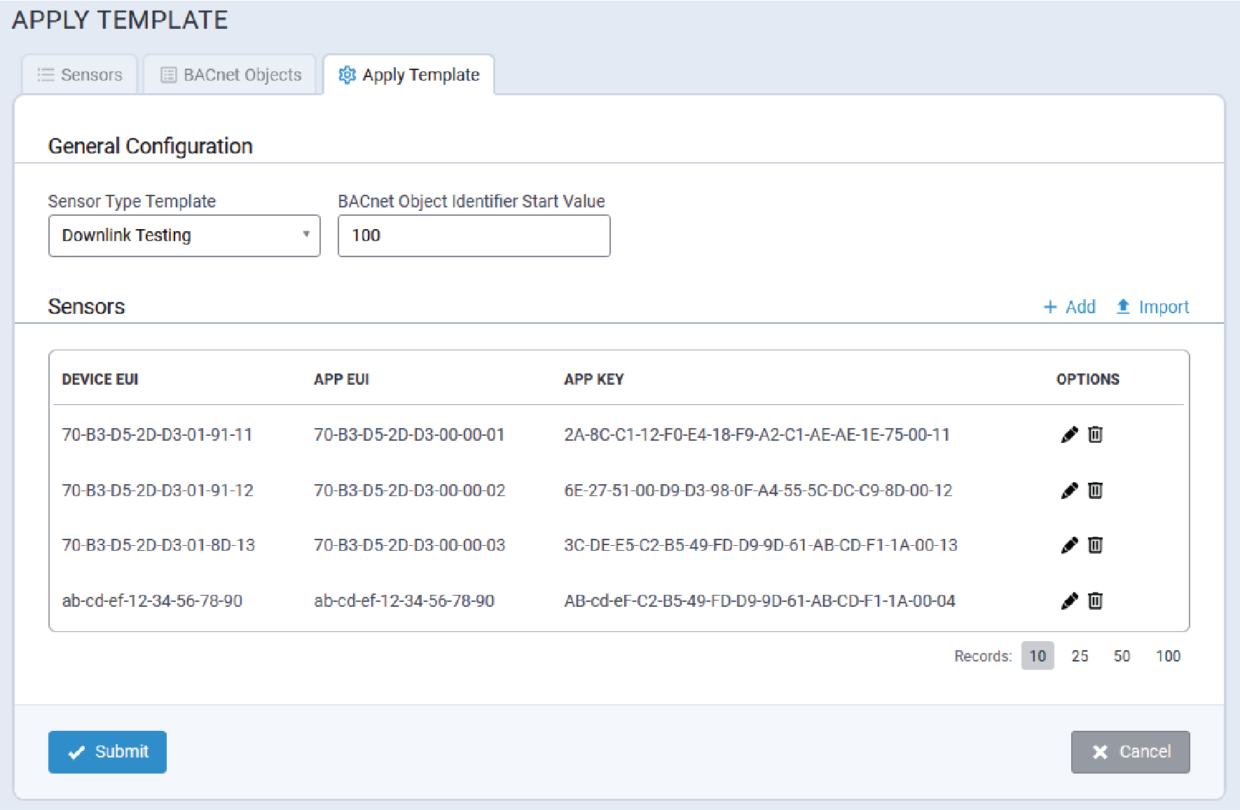
- Select the desired Sensor Type Template from the pull-down.
- Specify the BACnet Object Identifier Start Value.
- The system will increment this value for each new BACnet object added while applying the template.
- If the specified ID value is already in use, the system will skip it and apply a different value.
- Add sensor details using one of the following methods:
- Click + Add to manually add the following sensor information:
- Device EUI
- App EUI
- App Key
Note: Refer to Key Management for additional information. - Click Import to import sensor data from a CSV file.Note: Refer to Sensors Data CSV Files for complete information.
- Click + Add to manually add the following sensor information:
- Click Submit.
Sensors Data CSV Files
Sensor data can be formatted in a CSV file and then uploaded for use with templates. This is particularly helpful when applying a template to a large number of sensors.
Although the system does not require the CSV file to include a header, be aware of the following when creating sensor file:
If the sensor CSV file includes a header, when the file is uploaded the system searches for the DevEUI, AppEUI, and AppKey columns, parses the file, and retrieves only those values that are required. For example:
- If the sensor CSV file does NOT include a header, the first three columns of sensor data must be:
DevEUIAppEUIAppKey
DevEUI,AppEUI, andAppKey.
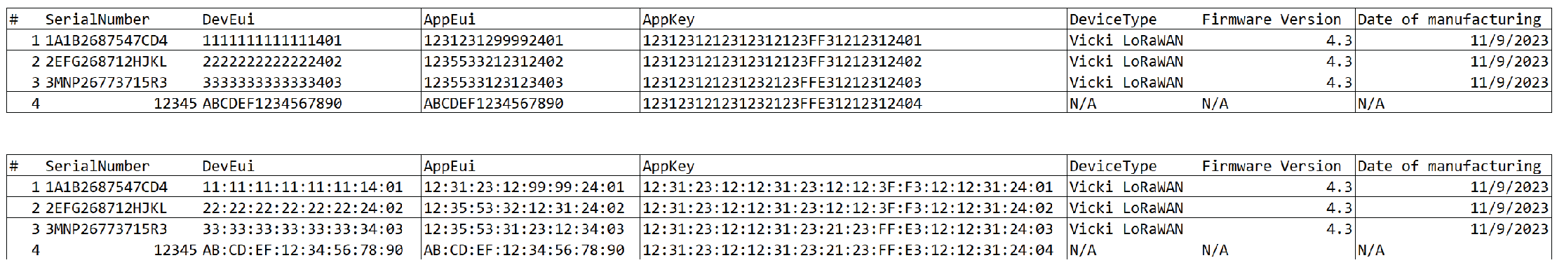

Edit Sensor Details
- Type
- Identifier
- Name
- Description
- On the Sensors page, click on the pencil icon associated with the sensor to be
edited. The Sensor Details dialog is displayed.
- Expand the Device EUI pull-down and select the desired EUI from the list. The system will display all BACnet objects for the selected Device EUI.
- From the list of BACnet Objects, locate the object to be edited, and click on
the corresponding pencil icon to display the BACnet Object details pop-up.

- Edit the fields as required.
- Click OK to save changes.
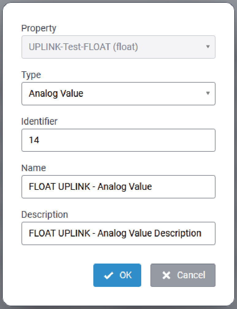
Delete Sensors
To delete a specific sensor, on the Sensors tab, locate the sensor that is to be
deleted and click on the corresponding ![]() icon. When prompted, confirm the deletion.
icon. When prompted, confirm the deletion.
To delete all sensors, click the ![]() Delete All icon/link on the top of the Sensors tab page. When prompted, confirm
the deletion.
Delete All icon/link on the top of the Sensors tab page. When prompted, confirm
the deletion.
Sensor Map JSON Files
mPower stores Sensor maps in JSON format.
Information for each sensor included in the system is structured as follows:
[
   {
      "id" : "",
      "sensor" : "",
      "src" : ""
   }
]| Parameter Name | Optional/Required | Value |
|---|---|---|
id |
Required | The 16-digit sensor Device EUI for the sensor in the format
|
sensor |
Required | The manufacturer's name and sensor model formatted as follows:
|
src |
Required |
This is currently the only supported value. This value is case-sensitive and must be lower case. |
[
   {
      "id" : "11-22-33-44-55-66-77-80",
      "sensor" : "elsys/EMS",
      "src" : "lora"
   },
   {
      "id" : "11-22-33-44-55-66-77-81",
      "sensor" : "elsys/ERSCO2",
      "src" : "lora"
   },
   {
      "id" : "00-10-20-30-40-50-60-70",
      "sensor" : "manufacturer/test",
      "src" : "lora"
   }
]
Import Sensor Map
The Sensor map being imported must be a properly-formatted JSON file as defined in Sensor Map JSON Files.
Perform the following procedure to import a JSON-formatted Sensor map:
- On the Sensors page, click the Import link at the top of the page.
- Click the Folder icon under Choose File and navigate to the desired JSON file.
- Click Import.
- Click Save and Apply.
Download the Sensor Map
- Click the Download link on the top of the Sensors page.
- When prompted, navigate to the directory where the Sensor map JSON file is to be saved.
- Click OK.
BACnet Objects Tab
BACnet Objects define the data transferred from a sensor to the BACnet explorer.
The BACnet Object tab displays the current BACnet Objects Map similar to this:
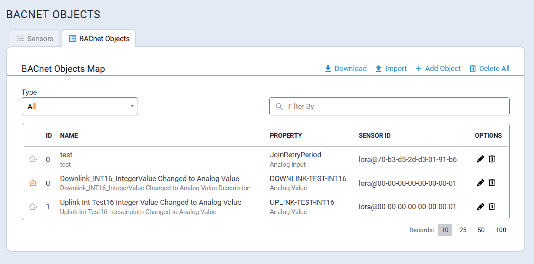
Filter BACnet Object Map
To filter the BACnet object map, enter the desired filter term in the Filter By field.
- Type
- ID
- Name
- Sensor ID
- Property
Edit a BACnet Object
- Type
- Identifier
- Name
- Description
- Within the BACnet Objects Map, click on the pencil icon associated with the
object to be edited. The BACnet Object details pop-up is displayed.
- Edit the fields as required.
- Click OK to save changes.
Add a BACnet Object
Perform the following procedure to add a new BACnet object:
- On the BACnet Objects tab page, click the Add Object link at the top of
the page. The Sensor Details dialog is displayed.

- Expand the Device EUI pull-down and select the EUI for the new BACnet
object.Note: A list of all BACnet objects for the selected EUI is then displayed.
- Click + Add Object. The New BACnet Object properties pop-up dialog is
displayed.

- Configure the following parameters:
Parameter Required/Optional Value Property Required A list of properties corresponding to the selected Device EUI. Type Required Available values are based on the configured Property value.
Refer to Supported BACnet Object Types for complete information.
Identifier Required Unique identifier for BACnet objects of the same type.
Numeric value: 0 - 4194302
Name Required Character string
Maximum length: 128 characters
Description Optional Character string
Maximum length: 128 characters
- Click OK.
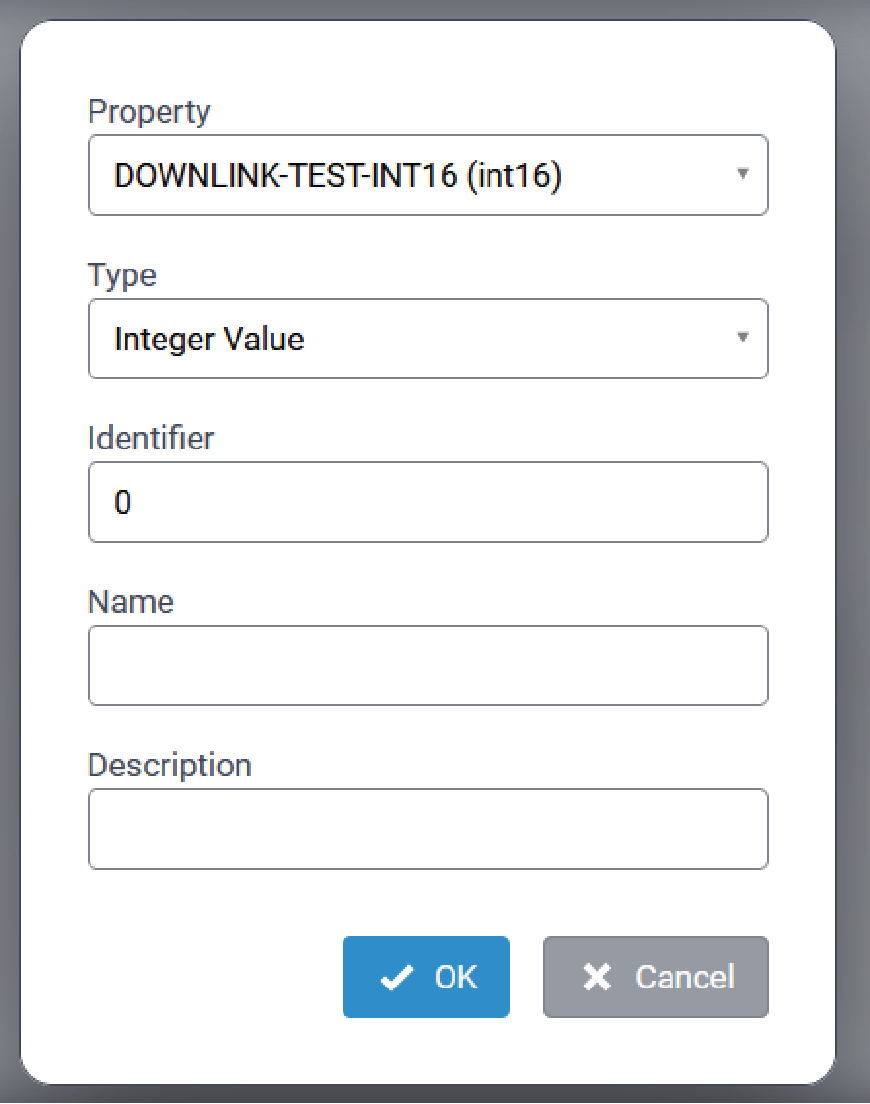
Supported BACnet Object Types
Supported BACnet object types vary based on UPLINK and DOWNLINK properties.
UPLINK BACnet Object Types
| Property Type | Supported BACnet Object Types |
|---|---|
| uint8 |
Analog Value, Analog Input, Positive Integer Value |
| uint16 | Analog Value, Analog Input, Positive Integer Value |
| uint32 | Positive Integer Value |
| int8 | Analog Value, Analog Input, Integer Value |
| int16 | Analog Value, Analog Input, Integer Value |
| int32 | Integer Value |
| float | Analog Value, Analog Input |
| bool | Binary Value, Binary Input |
| string | Character String Value |
DOWNLINK BACnet Object Types
| Property Type | Supported BACnet Object Types |
|---|---|
| uint8 |
Positive Integer Value, Analog Value |
| uint16 | Positive Integer Value, Analog Value |
| uint32 | Positive Integer Value |
| int8 | Integer Value, Analog Value |
| int16 | Integer Value, Analog Value |
| int32 | Integer Value |
| float | Analog Value |
| bool | Binary Value |
| string | Character String Value |
Delete BACnet Objects
To delete a specific BACnet object, on the BACnet Objects page, locate the object
that is to be deleted and click on the corresponding ![]() icon. When prompted, confirm the deletion.
icon. When prompted, confirm the deletion.
To delete all BACnet objects, click the ![]() Delete All icon/link on the top of the BACnet Objects page. When prompted,
confirm the deletion.
Delete All icon/link on the top of the BACnet Objects page. When prompted,
confirm the deletion.
BACnet Object Map JSON Files
mPower stores BACnet Object maps in JSON format. The JSON file includes any combination of the following object-type containers:
{
   "analog-inputs" : [],
   "analog-values" : [],
   "binary-inputs" : [],
   "binary-values" : [],
   "character-string-values" : [],
   "integer-values" : [],
   "positive-integer-values" : []
}
Each object-type container stores configuration details for each object of that type currently defined in the system.
Within each container, the BACnet object information is structured as follows:
[
   {
      "descr" : "",
      "key" : "",
      "name" : "",
      "oid" : 0
   }
]| Parameter | Optional/Required | Value |
|---|---|---|
descr |
Optional | Character string describing the object. This parameter may be empty. |
key |
Required | This value is formatted as follows:
where:
For example:
|
name |
Required | User-assigned name for the BACnet object. |
oid |
Required | Integer value. This value is unique for each BACnet object within an object type (e.g., analog-inputs, integer-values.) BACnet objects of different types may be configured with the same
|
{
   "analog-inputs" :
      [
         {
            "descr" : "",
            "key" : "lora@00-10-20-30-40-50-60-70@UPLINK-TEST-INT16",
            "name" : "UPLINK-TEST-INT16 - AI-6070",
            "oid" : 0
         }
      ],
   "analog-values" :
      [
         {
            "descr" : "",
            "key" : "lora@00-10-20-30-40-50-60-70@DOWNLINK-Test-FLOAT",
            "name" : "DOWNLINK-Test-FLOAT - AV-6070",
            "oid" : 0
         },
         {
            "descr" : "",
            "key" : "lora@00-10-20-30-40-50-60-70@UPLINK-TEST-INT16",
            "name" : "UPLINK-TEST-INT16 - AV-6070",
            "oid" : 1
         },
      ],
   "binary-inputs" :
      [
         {
            "descr" : "",
            "key" : "lora@00-10-20-30-40-50-60-70@UPLINK-Test-BOOL",
            "name" : "UPLINK-Test-BOOL - BI-6070",
            "oid" : 0
         }
      ],
   "binary-values" :
      [
         {
            "descr" : "",
            "key" : "lora@00-10-20-30-40-50-60-70@DOWNLINK-Test-BOOL",
            "name" : "DOWNLINK-Test-BOOL - BV-6070",
            "oid" : 0
         },
         {
            "descr" : "",
            "key" : "lora@00-10-20-30-40-50-60-70@UPLINK-Test-BOOL",
            "name" : "UPLINK-Test-BOOL - BV-6070",
            "oid" : 1
         }
      ],
   "character-string-values" :
      [
         {
            "descr" : "",
            "key" : "lora@00-10-20-30-40-50-60-70@DOWNLINK-TEST-STRING",
            "name" : "DOWNLINK-TEST-STRING - CSV-6070",
            "oid" : 0
         },
      ],
   "integer-values" :
      [
         {
            "descr" : "",
            "key" : "lora@00-10-20-30-40-50-60-70@DOWNLINK-TEST-INT16",
            "name" : "DOWNLINK-TEST-INT16 - IV-6070",
            "oid" : 0
         },
         {
            "descr" : "",
             "key" : "lora@00-10-20-30-40-50-60-70@DOWNLINK-TEST-INT32",
             "name" : "DOWNLINK-TEST-INT32 - IV-6070",
             "oid" : 1
         },
         {
            "descr" : "",
            "key" : "lora@00-10-20-30-40-50-60-70@DOWNLINK-TEST-INT8",
            "name" : "DOWNLINK-TEST-INT8 - IV-6070",
            "oid" : 2
         }
      ],
   "positive-integer-values" :
      [
         {
            "descr" : "",
            "key" : "lora@00-10-20-30-40-50-60-70@DOWNLINK-Test-UINT16",
            "name" : "DOWNLINK-Test-UINT16 - PIV-6070",
            "oid" : 0
         },
         {
            "descr" : "",
            "key" : "lora@00-10-20-30-40-50-60-70@DOWNLINK-Test-UINT32",
            "name" : "DOWNLINK-Test-UINT32 - PIV-6070",
            "oid" : 1
         }
      ]
}
Import BACnet Object Map
BACnet Objects may be added by importing a JSON-formatted BACnet Objects map.
The BACnet Objects map being imported must be a properly-formatted JSON file as defined in BACnet Object Map JSON Files.
Perform the following procedure to import a JSON-formatted BACnet Objects map file:
- On the BACnet Objects page, click the Import link at the top of the page.
- Click the Folder icon under Choose File and navigate to the desired JSON file.
- Click Import.
- Click Save and Apply.
Download the BACnet Objects Map
- Click the Download link on the top of the BACnet Objects page.
- When prompted, navigate to the directory where the BACnet Objects map JSON file is to be saved.
- Click OK.
Setup Menu
The Setup menu provides access to the following configuration settings:
- Network Interfaces
- WAN
- DNS
- DHCP
- LLDP
- SMTP
- SNMP
- Time
- Hardware
Network Interfaces
- eth0 is configured as LAN
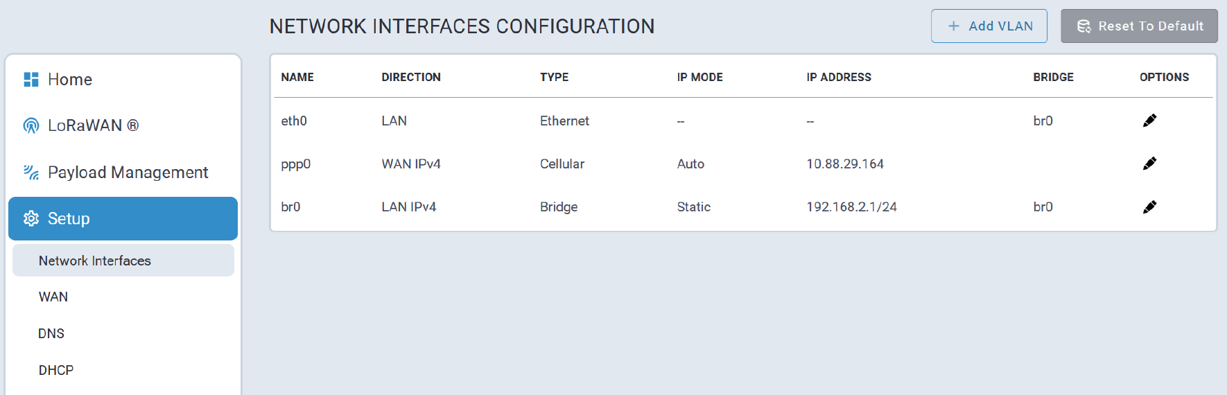
Configure eth0
To update the eth0 interface configuration, select the corresponding pencil icon in the OPTIONS column.
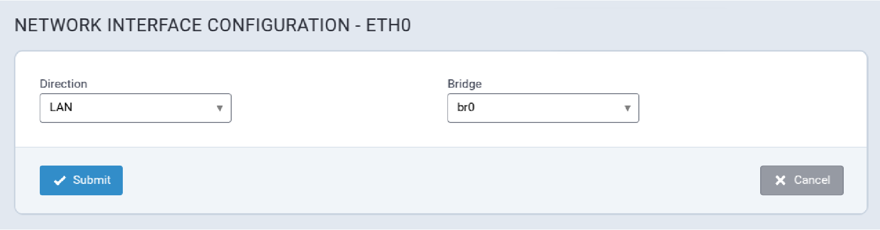
The eth0 interface can be removed from the bridge interface and configured independently by updating the Bridge field:
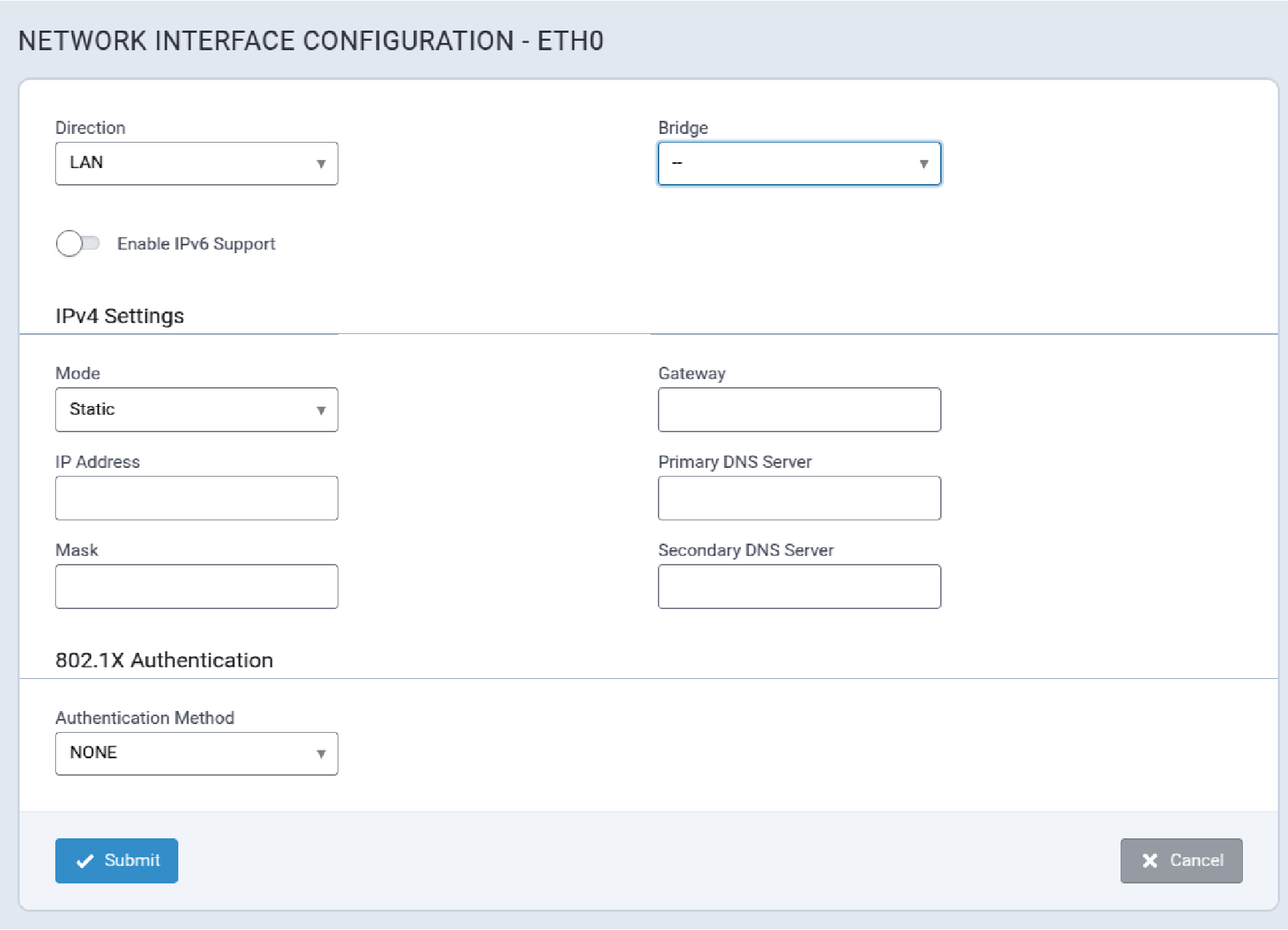
eth0 Configuration Parameters
| Parameter | Valid Values | Description |
|---|---|---|
| Direction | Valid values are:
|
WAN: Requires user-configured values for Gateway and Primary DNS
Server to function effectively. VLAN: Indicates a VLAN interface associated with the eth0 interface. |
| Bridge | Valid values are:
|
br0: eth0 is under the bridge. – :eth0 is independent of the bridge. |
| Enable IPv6 Support | Valid values are:
|
Enable IPv6 on the interface allowing delegated prefix or static IPv6 address settings. |
IPv4 Settings
| Parameter | Valid Values | Description |
|---|---|---|
| Mode | Valid values are:
|
Configures how the IP address for the Conduit® AP 300 will be
defined:
|
| Gateway | Default Route Gateway | |
| IP Address | Static IPv4 address to assign to the interface. | |
| Primary DNS Server | Primary DNS server for the network to which the interface is connected. | |
| Mask | The network mask for the network to which the interface will be assigned. | |
| Secondary DNS Server | Secondary DNS server for the network to which the interface is connected. |
802.1X Authentication
| Parameter | Valid Values | Description |
|---|---|---|
| Authentication Method | Valid values are:
|
Defines the authentication method for the Conduit® AP 300 on the network connected to the interface. |
Configure br0
The bridge (br0) interface has the following configuration options to manage all the LAN interfaces assigned to it:
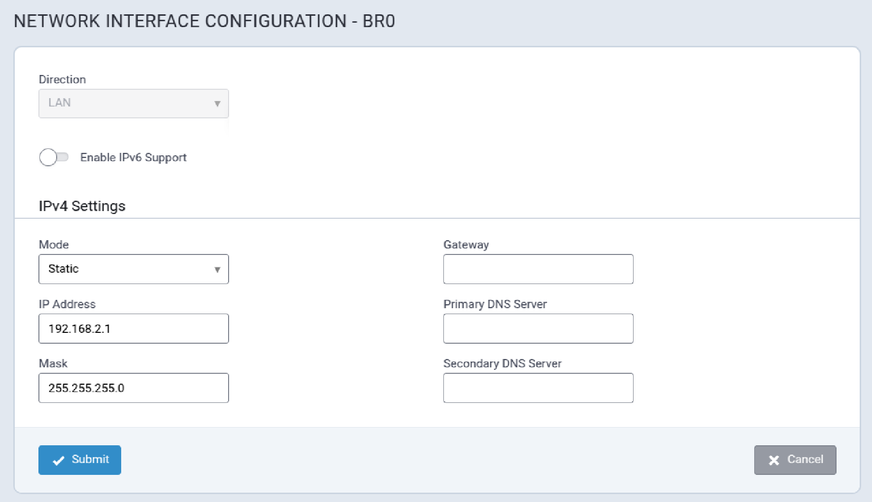
br0 Configuration Parameters
| Parameter | Valid Values | Description |
|---|---|---|
| Direction | Valid values are:
|
WAN: Requires user-configured values for Gateway and Primary DNS
Server to function effectively. VLAN: Indicates a VLAN interface associated with the eth0 interface. |
| Enable IPv6 Support | Valid values are:
|
Enable IPv6 on the interface allowing delegated prefix or static IPv6 address settings. |
IPv4 Settings
| Parameter | Valid Values | Description |
|---|---|---|
| Mode | Valid values are:
|
Configures how the IP address for the Conduit® AP 300 will be
defined:
|
| Gateway | Default Route Gateway | |
| IP Address | Static IPv4 address to assign to the interface. | |
| Primary DNS Server | Primary DNS server for the network to which the interface is connected. | |
| Mask | The network mask for the network to which the interface will be assigned. | |
| Secondary DNS Server | Secondary DNS server for the network to which the interface is connected. |
Add a VLAN Interface
Create a new VLAN interface, and then configure eth0 or WLAN1 to use VLAN with the specified VLAN ID.
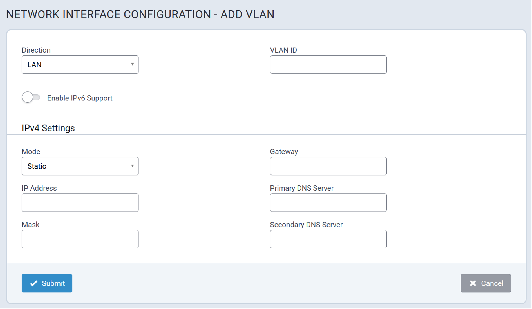
Typical VLAN interfaces are illustrated here:
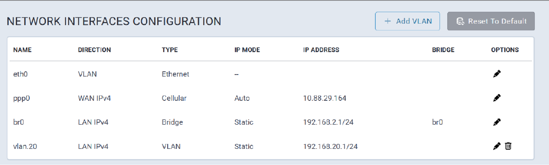
To configure an existing ethernet interface to use VLAN (eth0) select VLAN from the Direction pull-down list as shown here:
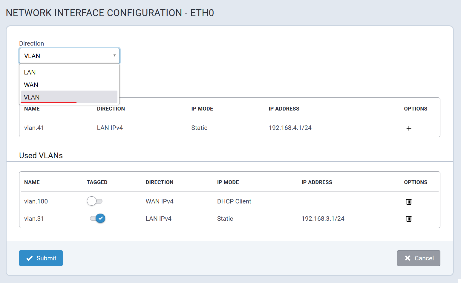
VLAN Configuration Parameters
| Parameter | Valid Values | Description |
|---|---|---|
| Direction | Valid values are:
|
WAN: Requires user-configured values for Gateway and Primary DNS
Server to function effectively. VLAN: Indicates a VLAN interface associated with the eth0 interface. |
| VLAN ID | Numerical value in the range 1 to 4094. | A unique numerical identifier assigned to the VLAN. |
| Enable IPv6 Support | Valid values are:
|
Enable IPv6 on the interface allowing delegated prefix or static IPv6 address settings. |
IPv4 Settings
| Parameter | Valid Values | Description |
|---|---|---|
| Mode | Valid values are:
|
Configures how the IP address for the Conduit® AP 300 will be
defined:
|
| Gateway | Default Route Gateway | |
| IP Address | Static IPv4 address to assign to the interface. | |
| Primary DNS Server | Primary DNS server for the network to which the interface is connected. | |
| Mask | The network mask for the network to which the interface will be assigned. | |
| Secondary DNS Server | Secondary DNS server for the network to which the interface is connected. |
WAN
A typical WAN Configuration page is illustrated here:
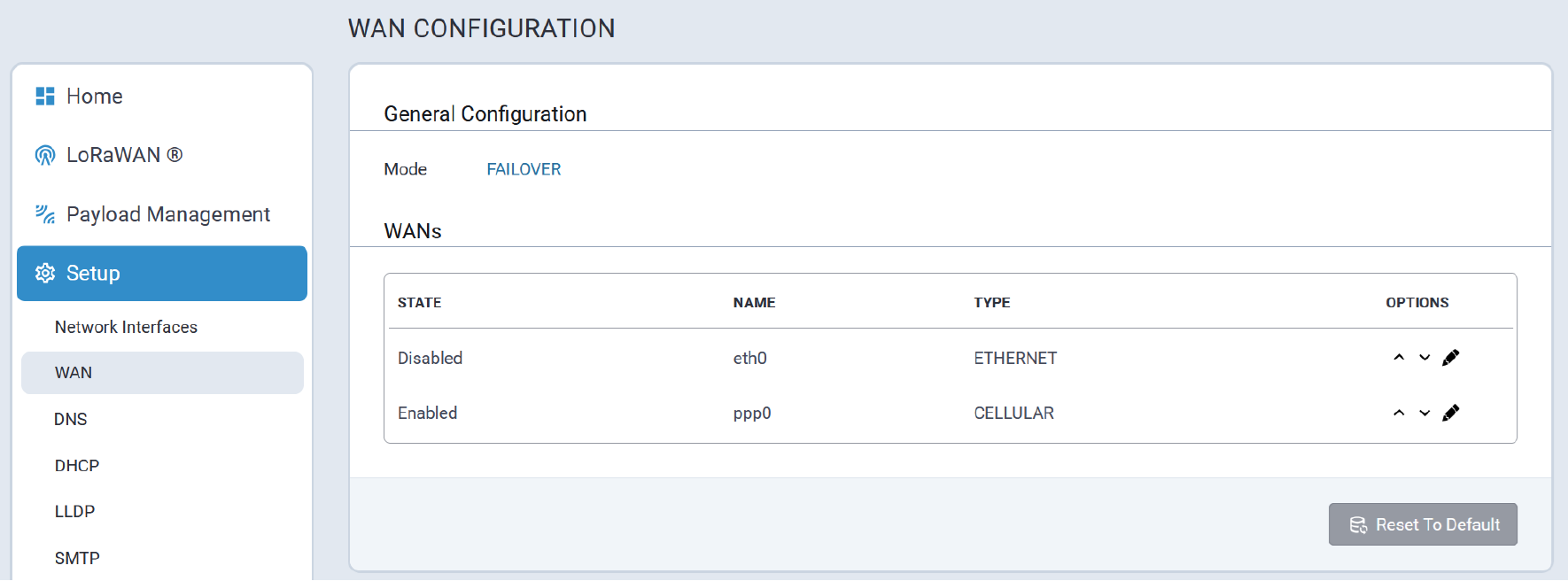
Any VLANs added to the system will also be displayed as shown here:
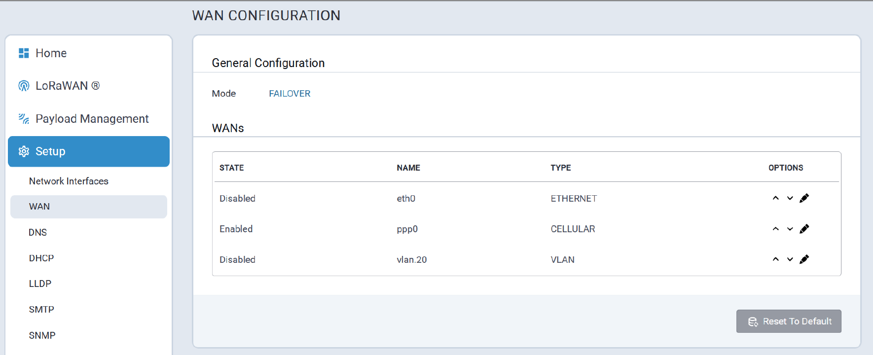
Each WAN interface can be configured for Active or Passive failover with a timeout interval to trigger failover to the next prioritized WAN interface.
Hostname must be specified and Mode Type selected (for example: ICMP for ping, TCP for an actual TCP connect attempt) to verify connectivity. The number of failures is controlled by the ICMP Count setting.
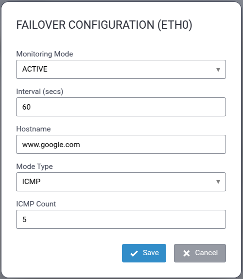
DNS
DNS configuration parameters for the Conduit® AP 300 are accessed via tabs included in this section as illustrated here:
Global DNS
A typical Global DNS Configuration page is illustrated here:
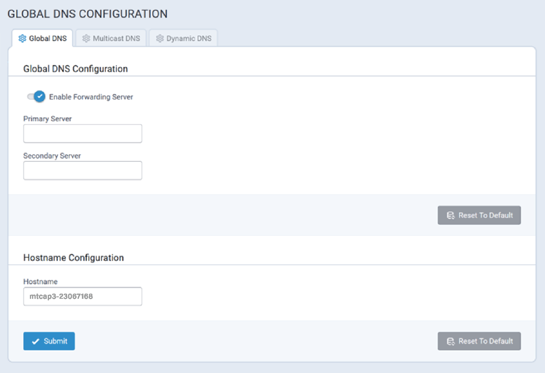
Global DNS enables user-defined DNS servers to be specified which are always used to resolve hostnames regardless of what WAN settings or interface are being used. If the Primary Server and Secondary Server are not specified, the DNS servers will default to those specified in the WAN Configuration setup.
For example, if cellular is the active WAN interface and the DNS settings are obtained from the provider, enabling this feature overrides the DNS server settings obtained from the provider with the settings that are specified here.
Configuration scenarios for Global DNS and Enable Forwarding Server, and the corresponding results (the device refers to a MultiTech device) include:
If Global DNS is not configured and forwarding is enabled, the Conduit® AP 300 acts as a proxy server for any devices on the LAN network(s).
- In this mode, the Conduit® AP 300 uses WAN DNS settings.
- Client Settings: On the client, you must configure the Conduit® AP 300 as the default gateway and DNS server. The easiest way to accomplish this is by using the DHCP server on the Conduit® AP 300.
If Global DNS is configured and forwarding is enabled, DNS requests are forwarded to servers configured in the Global DNS settings.
- The Conduit® AP 300 acts as a proxy.
- Client settings: Clients must be configured the same as in the previous case above.
If Global DNS is configured and forwarding is disabled, the default gateway and DHCP server on clients should point to the Conduit® AP 300, and the DNS servers on the client must use the same DNS as the Global DNS settings.
- Client settings: The client device uses the Conduit® AP 300 as a default gateway and DHCP server, but it must have DNS servers configured to the options that will be used.
- If neither item is configured/enabled, verify the Conduit® AP 300 is properly configure to forward DNS.
Configuration Parameters
Global DNS configuration parameters are described below.
Global DNS Configuration
| Parameter | Valid Values | Description |
|---|---|---|
| Enable Forwarding Server | Valid values are:
|
When enabled, the forwarding server is active and DNS is not supported. |
| Primary Server | IP address for the primary DNS server. | These servers override any DNS servers specified elsewhere in the UI. If no servers are configured, the system defaults to servers defined in WAN Configuration. |
| Secondary Server | IP address for the secondary DNS server. |
Hostname Configuration
Users can change the Hostname of the Conduit® AP 300 from its default value to a user-specified value to distinguish it from other Conduit® AP 300 devices on the network.
Enter the desired name in the Hostname field and click Submit to save the change.
To revert the name back to its default Hostname, click Reset To Default.
Multicast DNS
The Multicast DNS (mDNS) networking protocol resolves hostnames to IP addresses within small networks that do not include a local name server.
mDNS facilitates device access when Ethernet or Wi-Fi as WAN is enabled. Additionally, certain advanced settings may assist devices connected to the Conduit® AP 300 through different network interfaces in resolving each other's IP addresses by hostname.
A typical Multicast DNS configuration screen is illustrated here:
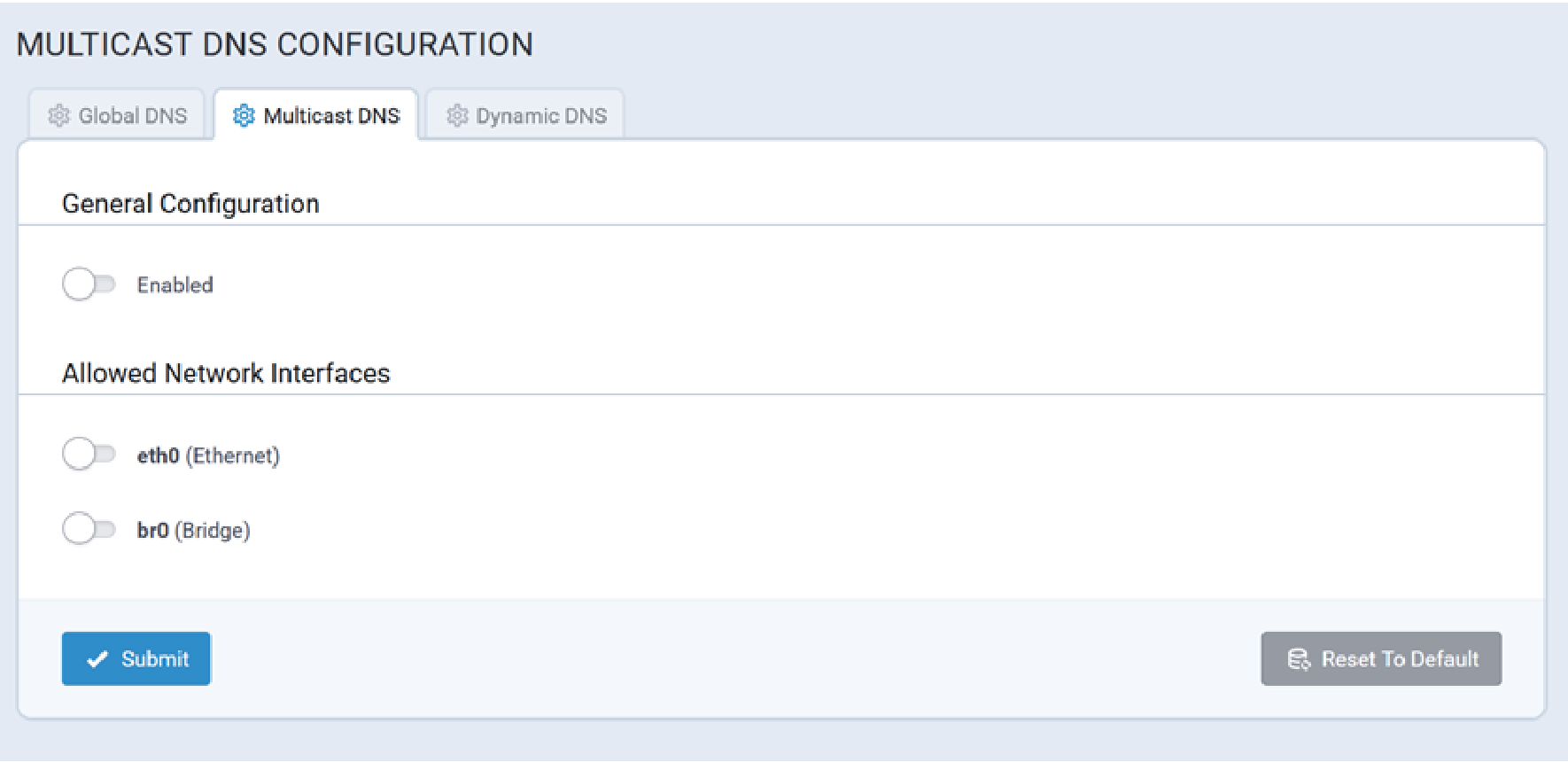
Configuration Parameters
Multicast DNS configuration parameters are described below. After you enable the mDNS feature and select the network interfaces, click Save & Apply to resolve your mPower device's IP address using its hostname to differentiate it from other devices in the same LAN.
General Configuration
By default, mDNS is disabled.
| Parameter | Valid Values | Description |
|---|---|---|
| Enabled | Valid values are:
|
Enables/disables Multicast DNS. Default Value: Disabled |
Allowed Network Interfaces
This list displays all available network interfaces, but not ppp0 (cellular). mDNS is not supported on the cellular network interface (ppp0). By default, all network interfaces are disabled.
| Parameter | Valid Values | Description |
|---|---|---|
| eth0 (Ethernet) | Valid values are:
|
Enables/disables the eth0 (Ethernet) interface. Default Value: Disabled |
| br0 (Bridge) | Valid values are:
|
Enables/disables the br0 (Bridge) interface. Default Value: Disabled |
| vlan.101 (VLAN) | Valid values are:
|
Enables/disables the vlan.101 (VLAN) interface. Default Value: Disabled Note: If a user deletes a virtual local area network (VLAN) interface, it is automatically removed from this list. |
Dynamic DNS
Typical Dynamic DNS configuration settings are illustrated here:
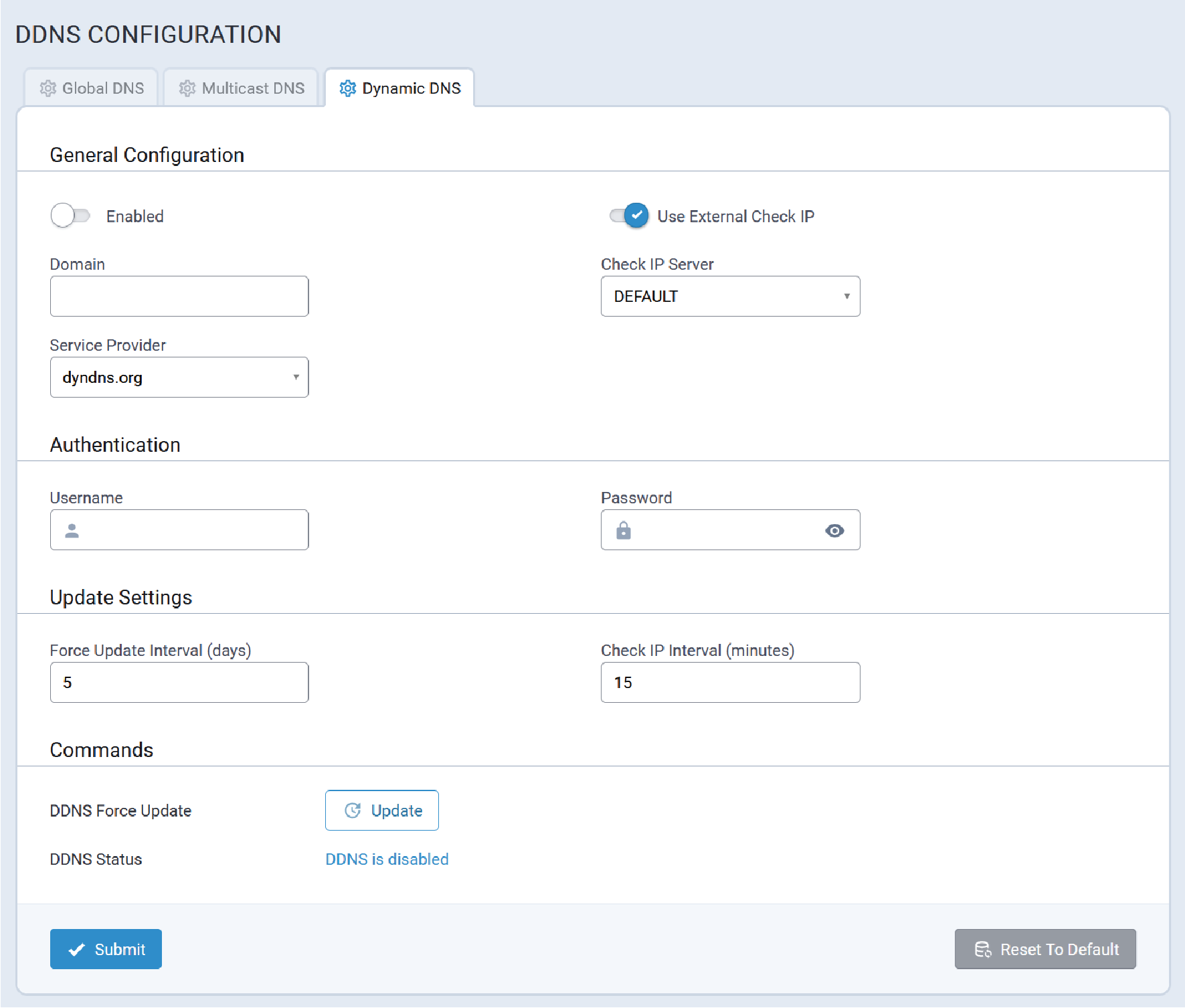
Configuration Parameters
Dynamic DNS configuration parameters are described below.
General Configuration
Refer to the following table for information about each DDNS configuration parameter:
| Parameter | Default Value | Valid Values |
|---|---|---|
| Enabled | FALSE | True, False |
| Use External Check IP | TRUE | True, False |
| Domain | empty | A valid domain name |
| Check IP Server | checkip.dyndns.org | A valid server name or IP Address, max length is 250 characters |
| Service Provider |
Authentication
| Parameter | Default Value | Valid Values |
|---|---|---|
| Username | empty | Max length is 128 characters |
| Password | empty | The value must be from 6 to 64 characters long |
Update Settings
| Parameter | Default Value | Valid Values |
|---|---|---|
| Force Update Interval (days) | 5 | Range is 1 - 30 days |
| Check IP Interval (minutes) | 15 | Range is 1 - 14400 minutes (10 days) |
Commands
| Parameter | Default Value | Value |
|---|---|---|
| DDNS Force Update | ||
| DDNS Status |
DHCP
The Conduit® AP 300 supports the configuration of IPv4 and IPv6 DHCP servers for all network interfaces that are configured as LAN, include new, user-created VLAN interfaces.
DHCP Configuration
A typical DHCP Configuration page is illustrated here:
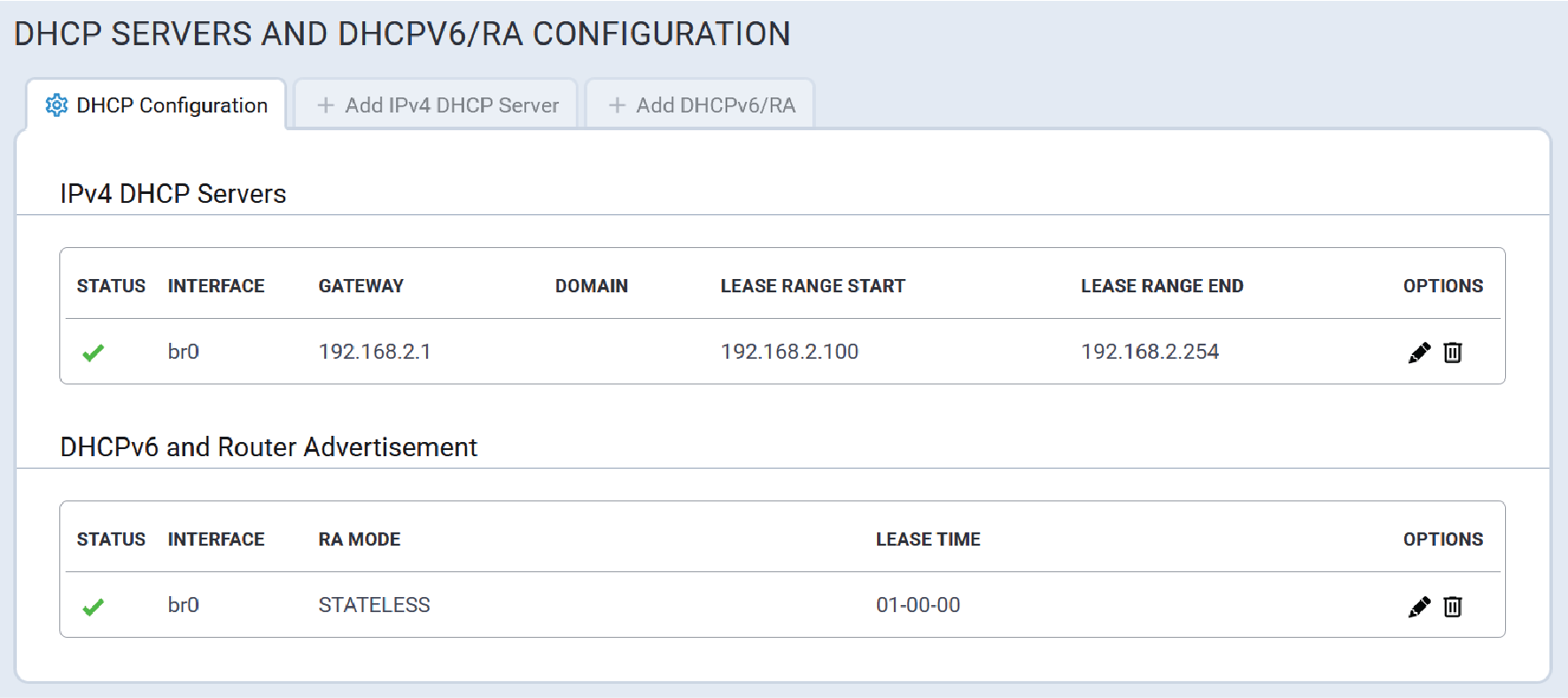
Add IPv4 DHCP Server
A typical Add IPv4 DHCP Server configuration page is illustrated here:
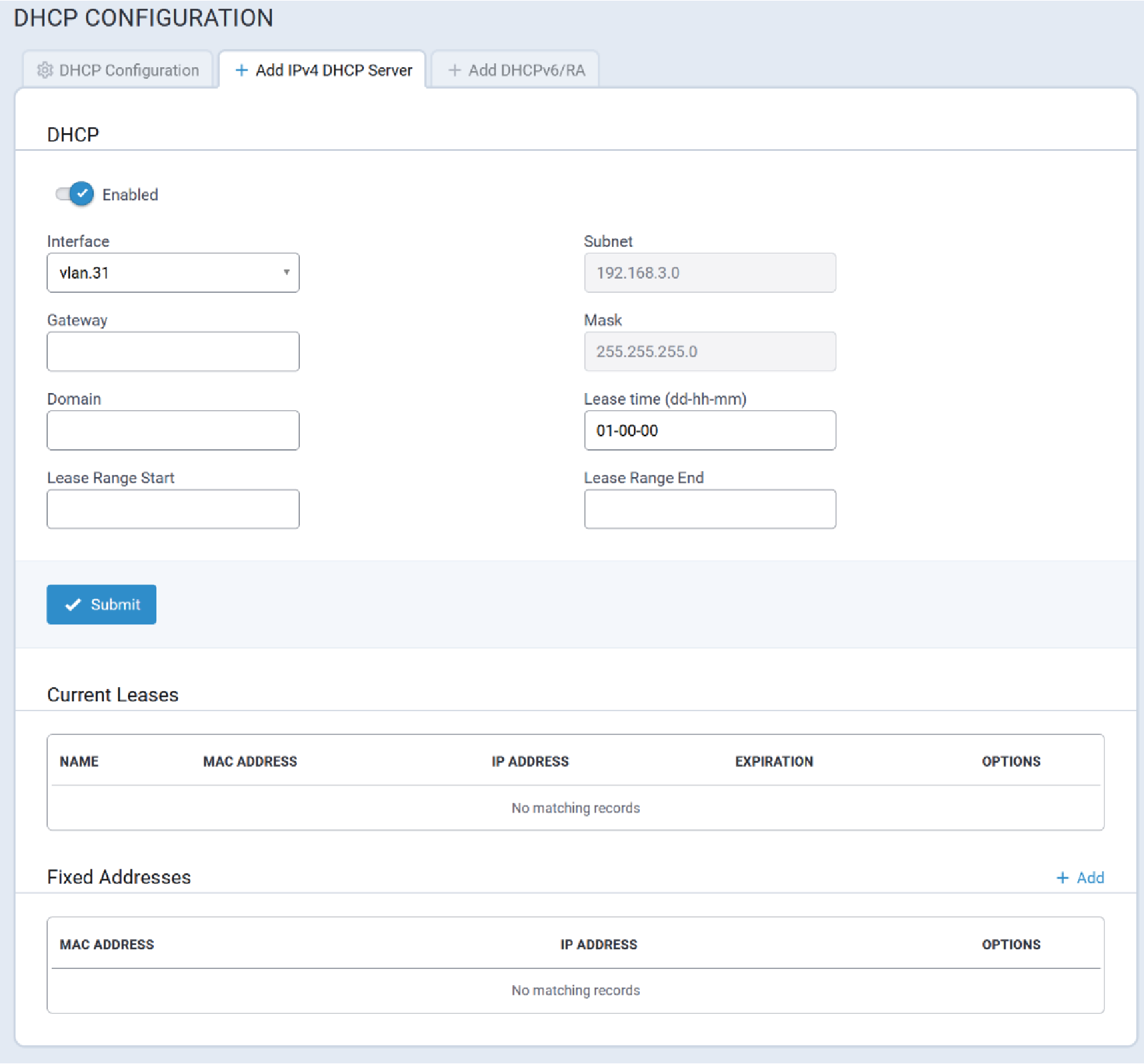
Add DHCPv6/RA
Typical DHCPv6 Router Advertisement (RA) configuration information is illustrated here:
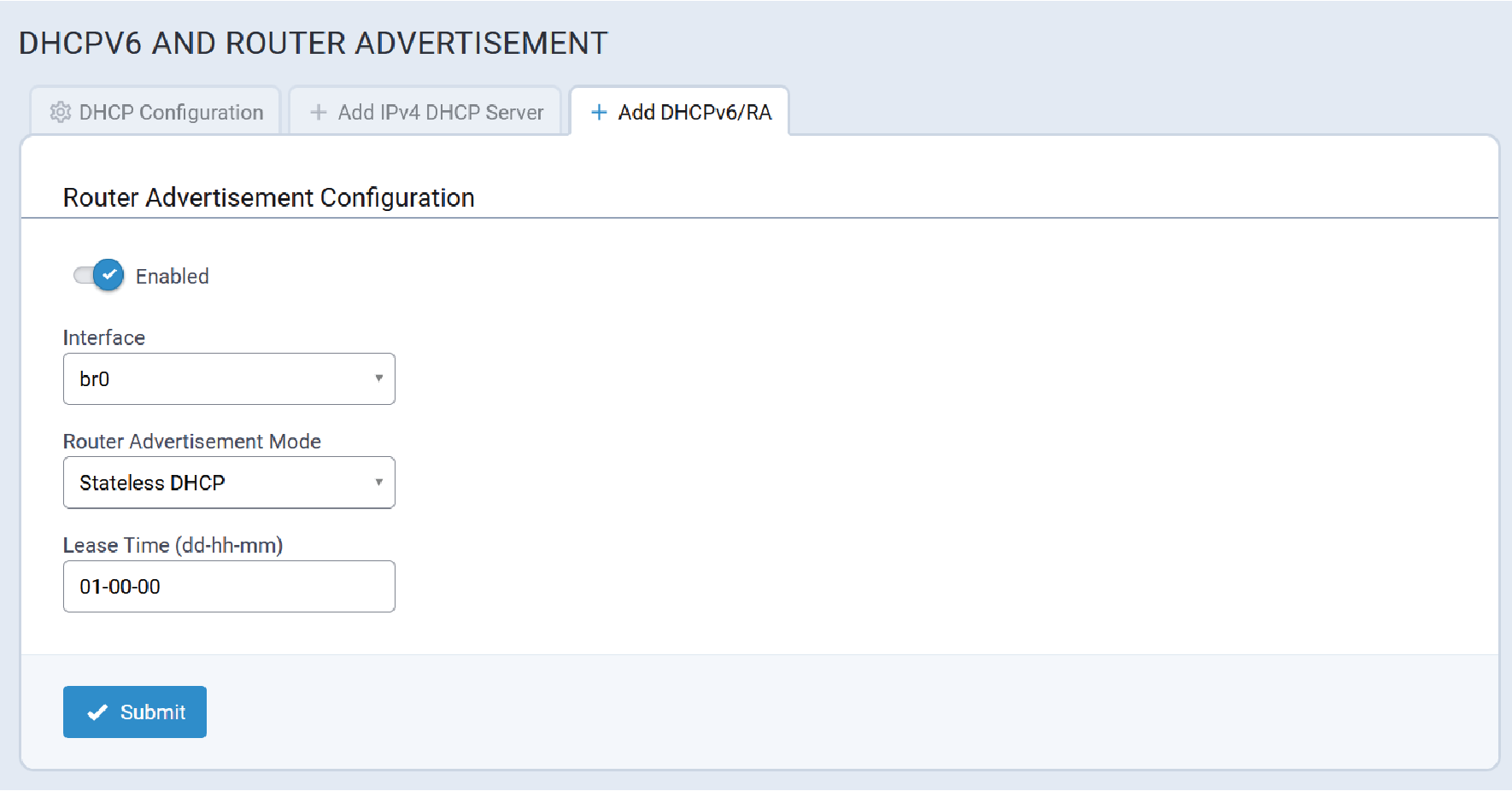
Edit DHCPv6/RA
Information for an existing DHCPv6/RA configuration is modified on this tab. Typical RA settings are illustrated here:
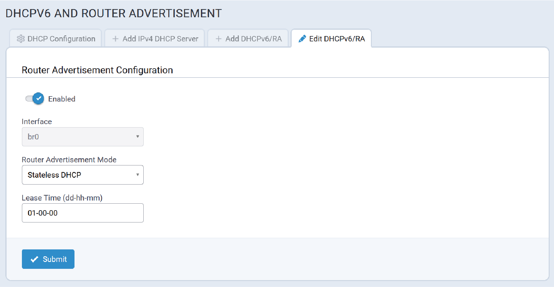
LLDP
Typical LLDP configuration settings for eth0 are illustrated here:
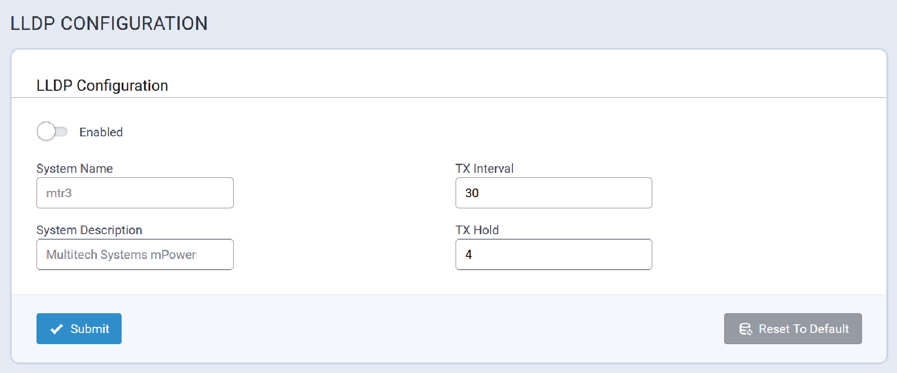
SMTP
The SMTP client is used to send notifications via email to a configured server.
A typical SMTP configuration page is illustrated here:
Typical SMTP configuration values are illustrated here:
Mail Log Tab
The Mail Log displays:
- Messages that are queued for sending
- Deferred messages
- Sent messages
For example, the Mail Log illustrated here shows two messages have been sent.
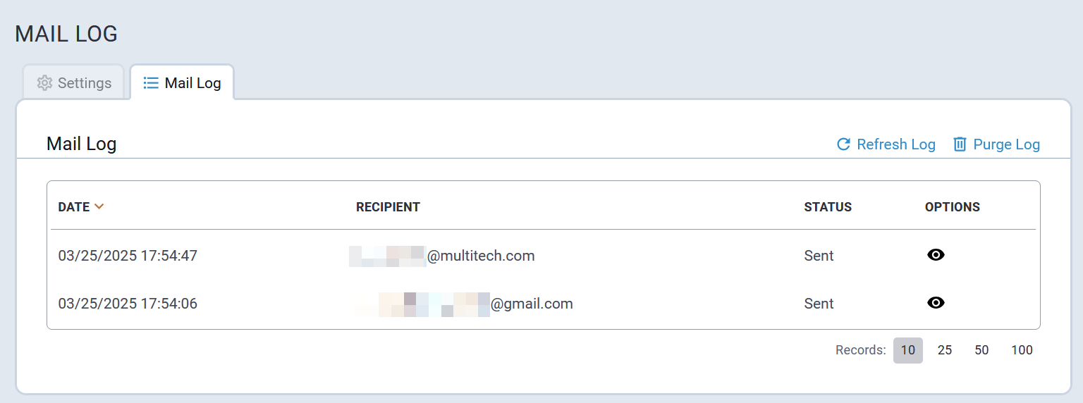
To view the details of a message, click on the ![]() icon in the OPTIONS column that corresponds with the desired
message. A dialog similar to the following will include the message details.
icon in the OPTIONS column that corresponds with the desired
message. A dialog similar to the following will include the message details.
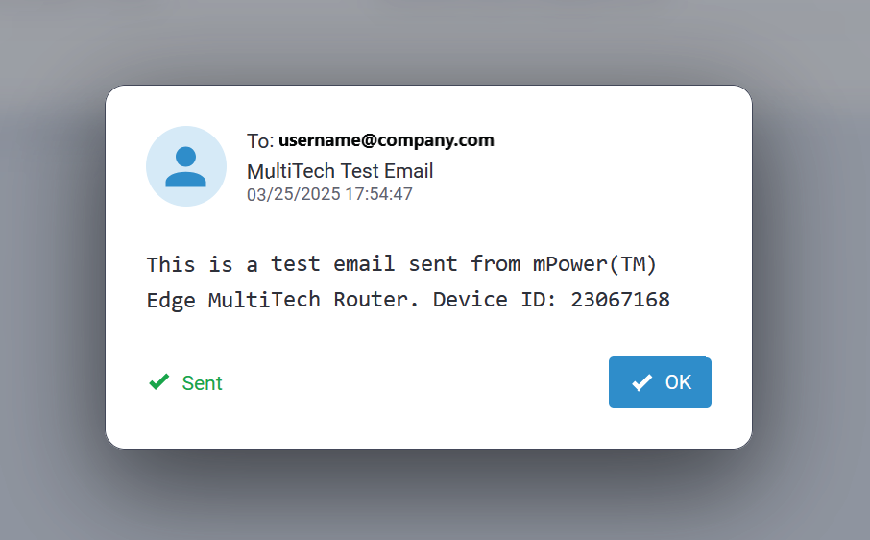
Settings Tab
A typical SMTP Configuration page is illustrated here:
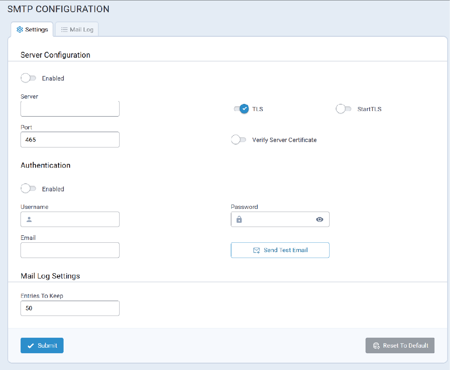
Mail Log Tab
The Mail Log displays:
- Messages that are queued for sending
- Deferred messages
- Sent messages
For example, the Mail Log illustrated here shows two messages have been sent.
To view the details of a message, click on the ![]() icon in the OPTIONS column that corresponds with the desired
message. A dialog similar to the following will include the message details.
icon in the OPTIONS column that corresponds with the desired
message. A dialog similar to the following will include the message details.
SNMP
A typical SNMP Configuration page is illustrated here:
| MIB Parameter | OID | OID Description | Comments |
|---|---|---|---|
| sysDescr | 1.3.6.1.2.1.1.1 | A textual description of the entity. This value should include the full name and version identification of the system's hardware type, software operating-system, and networking software. It is mandatory that this only contain printable ASCII characters. |
The system returns the following information:
|
| sysObjectID | 1.3.6.1.2.1.1.2 | The vendor's authoritative identification of the network management subsystem contained in the entity. This value is allocated within the SMI enterprises subtree (1.3.6.1.4.1) and provides an easy and unambiguous means for identifying the type of box being managed. For example, if vendor "Flintstones, Inc." is assigned the subtree 1.3.6.1.4.1.4242, it could assign the identifier 1.3.6.1.4.1.4242.1.1 to "Fred Router". |
The sysObjectID is 1.3.6.1.4.1.995.16.1.2.1 |
| sysUpTime | 1.3.6.1.2.1.1.3 | The time (in hundredths of a second) since the network management portion of the system was last re-initialized. | The uptime of the snmp service. |
| sysContact | 1.3.6.1.2.1.1.4 | The textual identification of the contact person for this managed node, together with information on how to contact this person. |
Empty by default. Configurable. |
| sysName | 1.3.6.1.2.1.1.5 | An administratively-assigned name for this managed node. By convention, this is the node's fully-qualified domain name. |
Empty by default. Configurable. |
| sysLocation | 1.3.6.1.2.1.1.6 | The physical location of this node ("telephone closet on 3rd floor"). |
Empty by default. Configurable. |
| sysServices | 1.3.6.1.2.1.1.7 | A value which indicates the set of services that this entity primarily offers. The value is a sum which initially has the value zero (0). Then, for each layer, L, in the range 1 - 7, for which a node performs transactions, 2(L - 1) is added to the sum. For example, a node which primarily performs routing functions has a value of (2(3-1)), or 4. In contrast, a node which is a host offering application services has a calculated value of [2(4-1) + 2(7-1)], or 72. Note that in the context of the Internet suite of protocols, values should be calculated accordingly:
For systems including OSI protocols, layers 5 and 6 may also be included. |
mPower devices will return 76. |
Time
The time synchronization feature sets up device time according to the specified system settings. Two different options are used to get the correct time:
- NTP Synchronization
- Cellular Synchronization
A typical Time Configuration page is illustrated here:
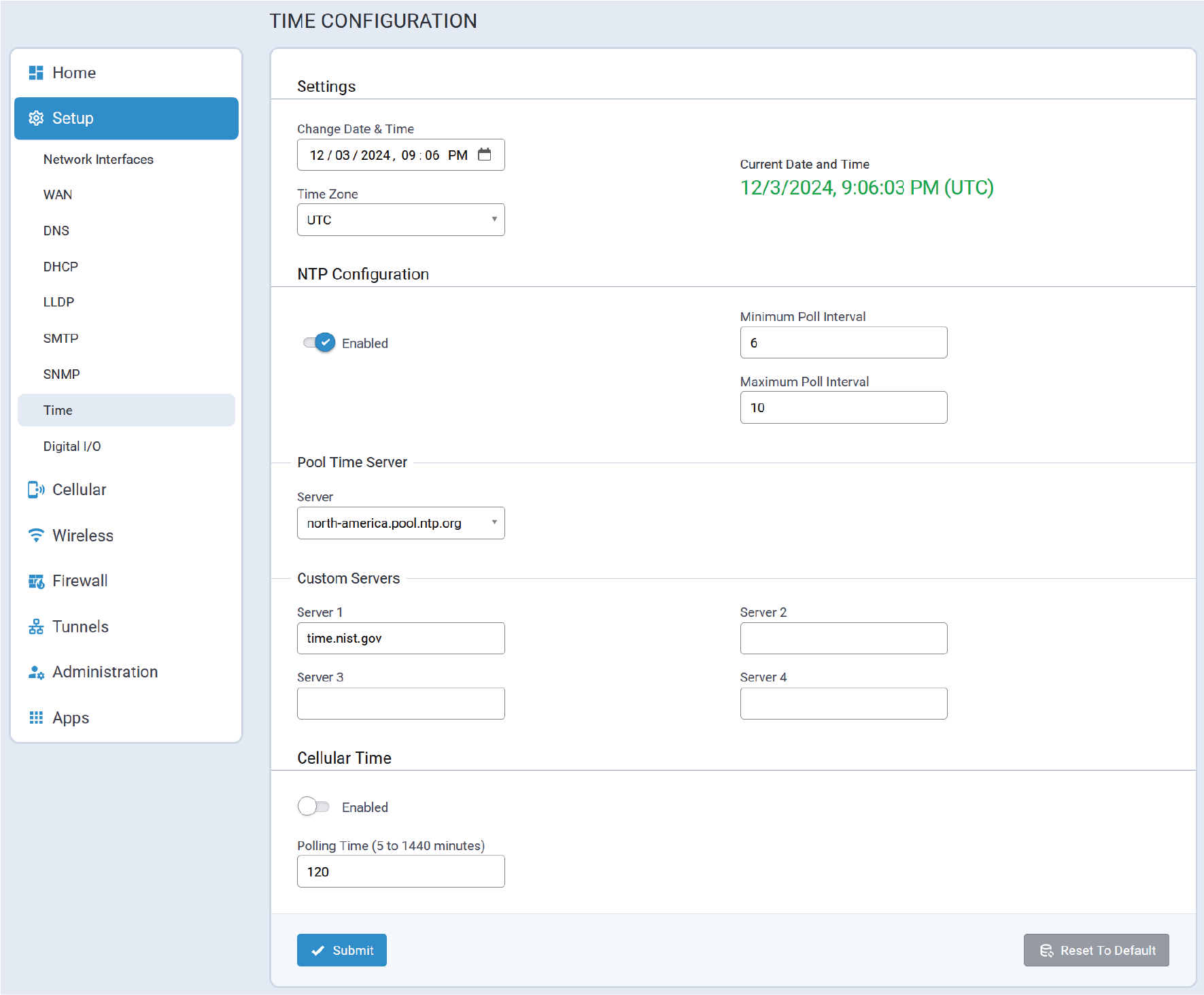
Time Configuration Parameters
Settings
| Parameter | Valid Values | Description |
|---|---|---|
| Change Date & Time | Manually adjust the date and time to correspond with the geographic location of the Conduit® AP 300. | |
| Time Zone | Select the time zone from the pull-down list that corresponds to the geographic location of the Conduit® AP 300. | |
| Current Date and Time | Displays the current date and time. |
| Parameter | Valid Values | Description |
|---|---|---|
| Enabled | Valid values are:
|
Enables/disables Network Time Protocol (NTP)
synchronization. Default Value: Enabled |
| Minimal Poll Interval | Whole numeric values. | Minimum time duration, in minutes, for the Conduit® AP 300 to poll the selected time server to
synchronize its time. Default value: 6 |
| Maximum Poll Interval | Whole numeric values. | Maximum time duration, in minutes, for the Conduit® AP 300 to poll the selected time server to
synchronize its time. Default value: 10 |
| Pool Time Server | ||
| Server | Select the desired pool time server from the pull-down list. | |
| Custom Servers | ||
| Server 1 | URL | URL of a custom time server to be used for time synchronization by the Conduit® AP 300. |
| Server 2 | URL | URL of a custom time server to be used for time synchronization by the Conduit® AP 300. |
| Server 3 | URL | URL of a custom time server to be used for time synchronization by the Conduit® AP 300. |
| Server 4 | URL | URL of a custom time server to be used for time synchronization by the Conduit® AP 300. |
| Parameter | Valid Values | Description |
|---|---|---|
| Enabled | Valid values are:
|
Enables/disables cellular time synchronization. Default Value: Disabled |
| Polling Time | Valid values are:
|
Time duration, in minutes, for the Conduit® AP 300 to poll the cellular network to
synchronize its time. Default value: 120 |
Hardware Configuration
The hardware configuration page is used to enable or disable the USB port, which is disabled by default.
A typical hardware configuration page is illustrated here:

To enable or disable the USB port, use the toggle and then select Submit. After the Save and Apply button turns red, click Save and Apply. A dialog similar to the following will include the requirement to reboot the system.

When the USB port is enabled, and the system detects a connected device, the device Vendor ID and Product Name (VID:PID) and device description are shown on Web UI and is available in /api/stats/extUsb.
Web UI keeps polling the /api/stats/extUSB value every 15 seconds. For example, if the USB device is disconnected, this information will be automatically updated on Web UI within 15 seconds or if the user manually refreshes the page.

The Reset USB Port button is always available, regardless of whether the USB port is enabled or disabled.

Cellular Menu
Cellular features such as Cellular connection, cellular diagnostics, and SMS related functionality are configured within this menu.
Cellular Configuration
- Enables/disables cellular operation
- Configures Connection Monitoring parameters
- Configures Connection Recovery parameters.
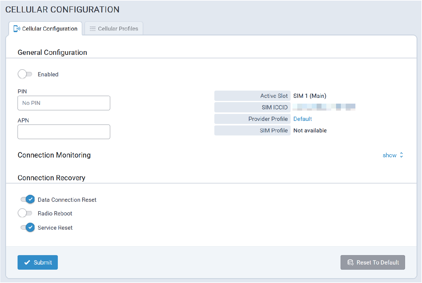
Cellular Configuration Tab
The Cellular Configuration tab includes settings that users must manage in order for their Cellular Connection to work.
General Configuration
The following General Configuration settings are configured in this area:
- Cellular operation is enabled/disabled.
- If the SIM is locked, the PIN must be configured for it.
- If the customer has a custom APN or is using an MVNO, they may be required to manually configure the APN.
Connection Monitoring
Connection Monitoring settings are configured in this area:
- Max Connection Failures – This setting, when enabled, tracks up to the maximum attempts before the additional connection recover activities begin.
- Keep Alive – This is essentially a Ping keep-alive to verify that the data connection is still established and data can be transmitted and received.
- Data Receive Monitor – This is a passive monitor. If the device has not received any packets over the Cellular connection in the configured window it will trigger connection re-establishment activities.
- Network Registration Timeout – If enabled, and the radio is unable to register with the Cellular network in the timeout specified, the Cellular recovery procedures are triggered.
- Roaming Network Timeout – If enabled, if the radio is connected in roaming it will attempt to reconnect to its home network per the timeout setting.
- Signal Quality Timeout – If the RSSI remains below the specified dBm for the timeout period, the recovery procedures are started in order to attempt to find better signal.
Connection Recovery
Connection Recovery settings are enabled/disabled in this area:
- Data Connection Reset – If it is determined that the data connection is not passing traffic the connection will be re-established.
- Radio Reboot – If this is enabled, after all back-off timers have been exercised, and if the data connection has not been re-established successfully during that time, the radio is rebooted.
- Service Reset – Per algorithm, the entire set of processes, counters, etc., will be restarted at a point if Cellular data connectivity cannot be re-established.
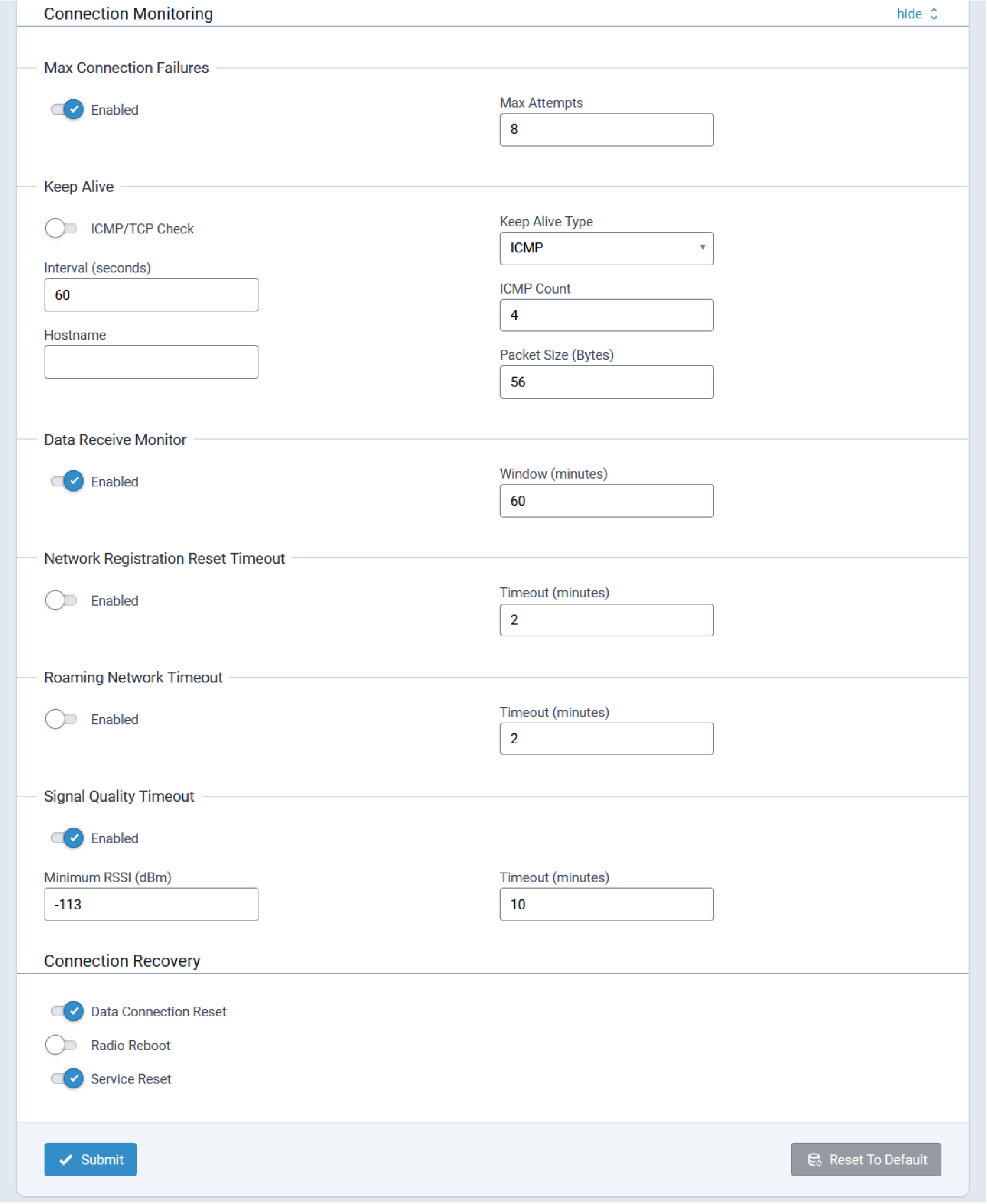
Cellular Profiles Tab
The system supports the configuration of Cellular Provider Profiles and SIM profiles.
The system applies a corresponding Provider Profile and SIM profile based on the settings configured by users.
Default Cellular Profile configuration settings are illustrated here:
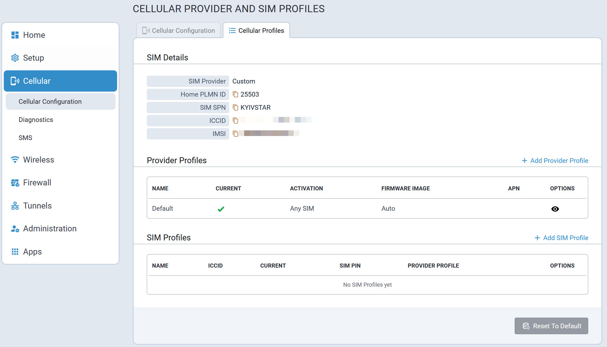
Provider profiles support the configuration of Cellular Management settings such as private network APNs, specific settings for different types of SIMs, etc. What is powerful about these profiles is the ability to customize on a provider basis the configuration values that are not defaults or supported through default behavior.
Add Provider Profile Tab
To create a new Provider Profile, select + Add Provider Profile on the Cellular Profiles tab.
The Add Provider Profile tab is then displayed allowing users to configure the new provider profile.
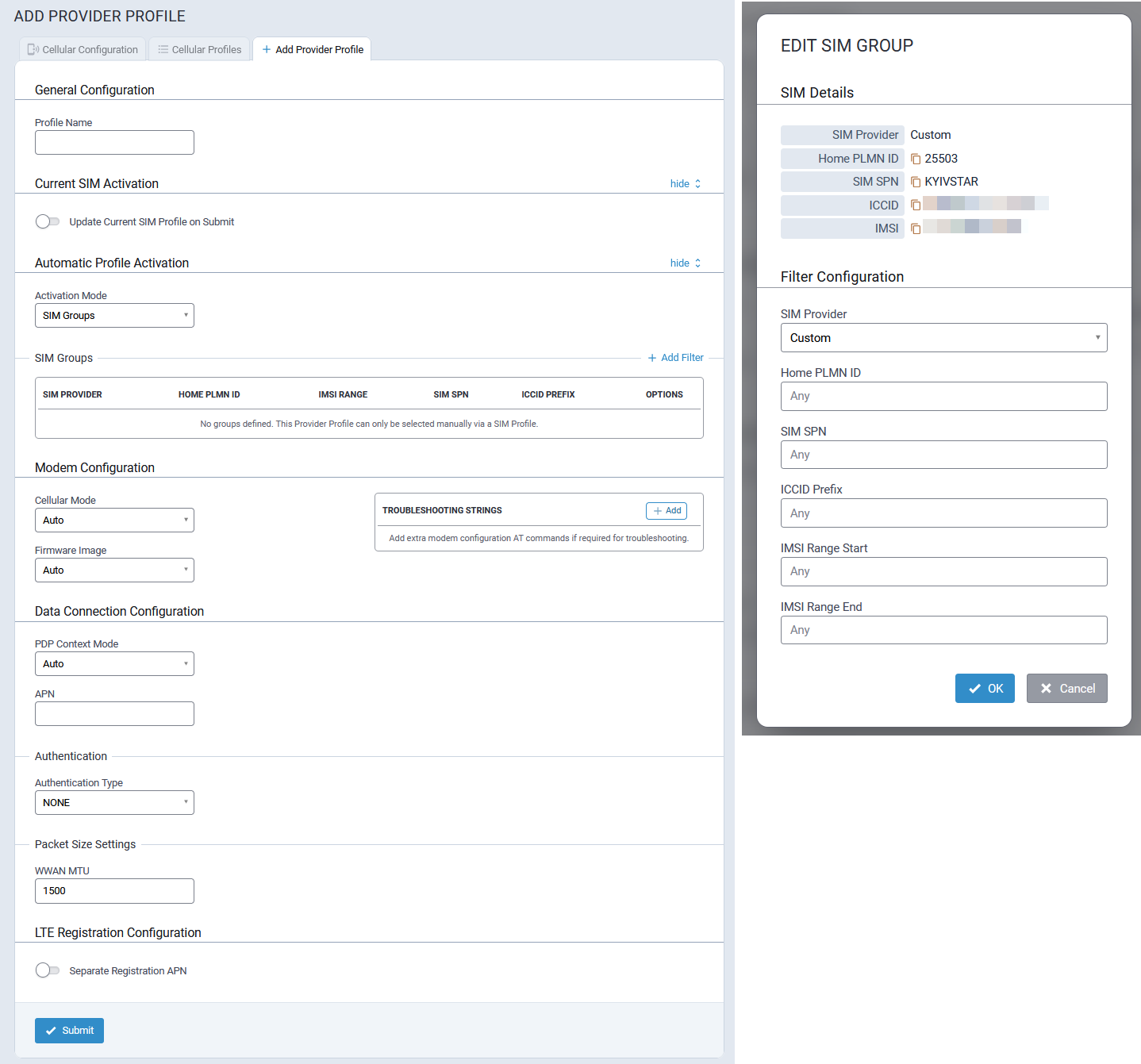
Edit SIM Group
When updating the SIM groups for a profile, what is happening is that each group added is a filter to match only the SIM profiles to be used with the provider profile you are defining groups for. It is possible to have multiple groups which are multiple filters that match different groups of SIMs.
Add SIM Profile Tab
When adding a new provider profile, it is possible to create a SIM group that will be used with that provider profile.
To create a new SIM Profile, select + Add SIM Profile on the Cellular Profiles tab.
The Add SIM Profile tab is then displayed allowing users to configure the new SIM profile.
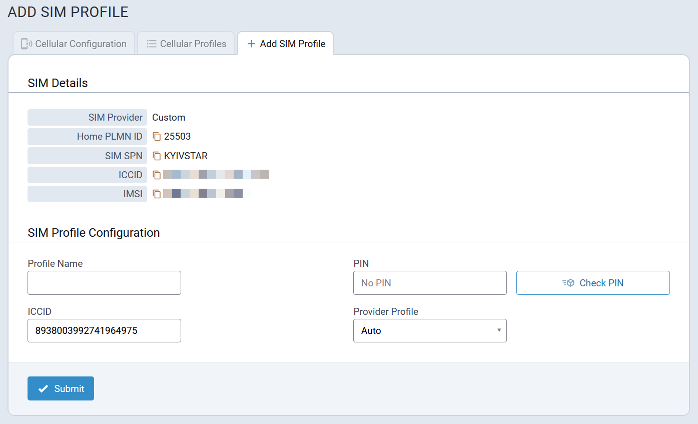
Diagnostics
Cellular Diagnostics includes the following tabs:
- Radio Status
- Cellular Scan
- Diagnostics
- Cell Radio Firmware Upgrade
Radio Status Tab
Typical Radio Status information is illustrated here:
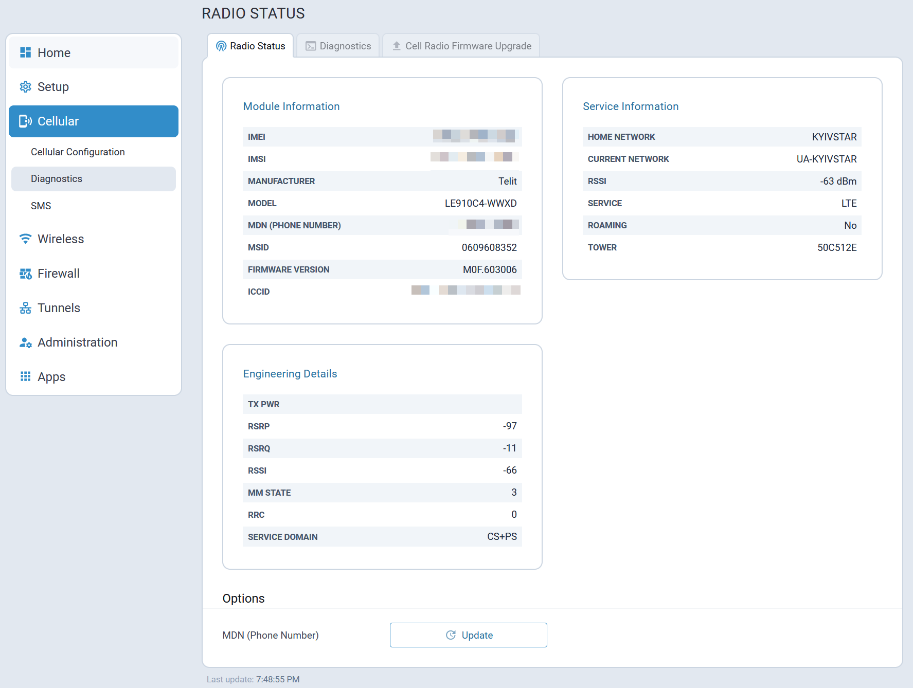
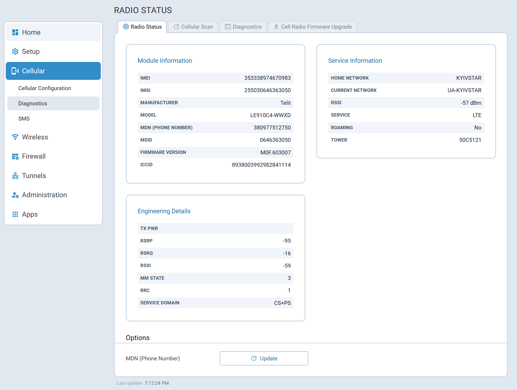
Cellular Scan Tab
The system allows users to manually perform cellular scans for available LTE (4G), WCDMA (3G), and GSM (2G) network types.
A typical Cellular Scan tab is illustrated here:
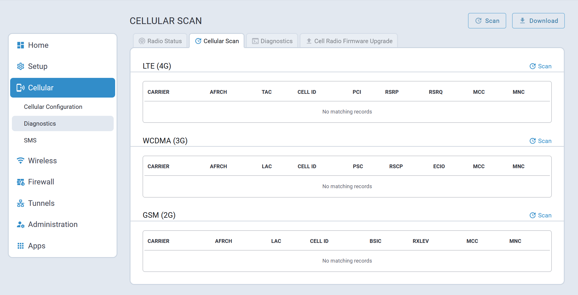
To perform a cellular scan for all available network types (4G, 3G, and 2G), click Scan at the top of the page.
To perform a cellular scan for a particular network type, click Scan in a corresponding network type section on the page. This initiates a scan for only the corresponding network type.
The scan results are displayed in a separate table for each cellular network type.
| Field Name | Description | LTE (4G) | WCDMA (3G) | GSM (2G) |
|---|---|---|---|---|
| CarrierName | The name of the mobile network operator | X | X | X |
| Frequency | The radio frequency band used by the cellular network | X | X | X |
| CellId | The unique identifier for the cell tower | X | X | X |
| MCC | A three-digit code that identifies the country of the network | X | X | X |
| MNC | A two or three-digit code that identifies the mobile operator within a country | X | X | X |
| RAT | Radio Access Technology, the type of cellular network (LTE or 4G, WCDMA or 3G, GSM or 2G) | X | X | X |
| LAC | Location Area Code identifies a group of cell towers in 2G and 3G networks | X | X | |
| BSIC | Base Station Identity Code, a unique code used in GSM (2G) networks to identify the cell | X | ||
| RxLev | Received Signal Level, a measure of signal strength, is primarily used for 2G networks | X | ||
| PSC | Primary Scrambling Code, a unique code used to identify a cell in 3G networks | X | ||
| RSCP | Received Signal Code Power, a measure of signal strength for 3G networks | X | ||
| ECIO | Energy per Chip per Noise, a measure of signal quality and interference for 3G networks | X | ||
| PCI | Physical Cell ID, a unique code used to identify a cell in 4G and 5G networks | X | ||
| TAC | Tracking Area Code, identifies a group of cell towers in 4G and 5G networks | X | ||
| RSRP | Reference Signal Received Power, the primary measure of signal strength for 4G and 5G network | X | ||
| RSRQ | Reference Signal Received Quality, a measure of signal quality and interference for 4G and 5G networks | X |
To download the latest scan results, select Download. The download file is in CSV format with a file name in the following format: cellular_scan_[productID]_[engineeringVersion]_MM-DD-YY.csv
An example of downloaded scan results is illustrated here:
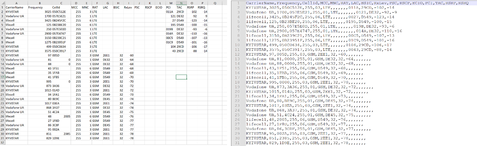
Diagnostics Tab
The Diagnostics tab includes:
- The Radio Terminal in which users can execute AT commands
- Radio Diagnostics feature which allows users to download cellular related logs and details
- Reset Options which allow the modem to be reset
A typical Diagnostics tab is illustrated here:
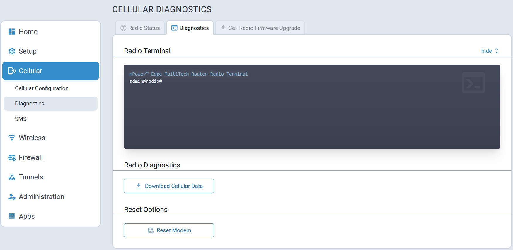
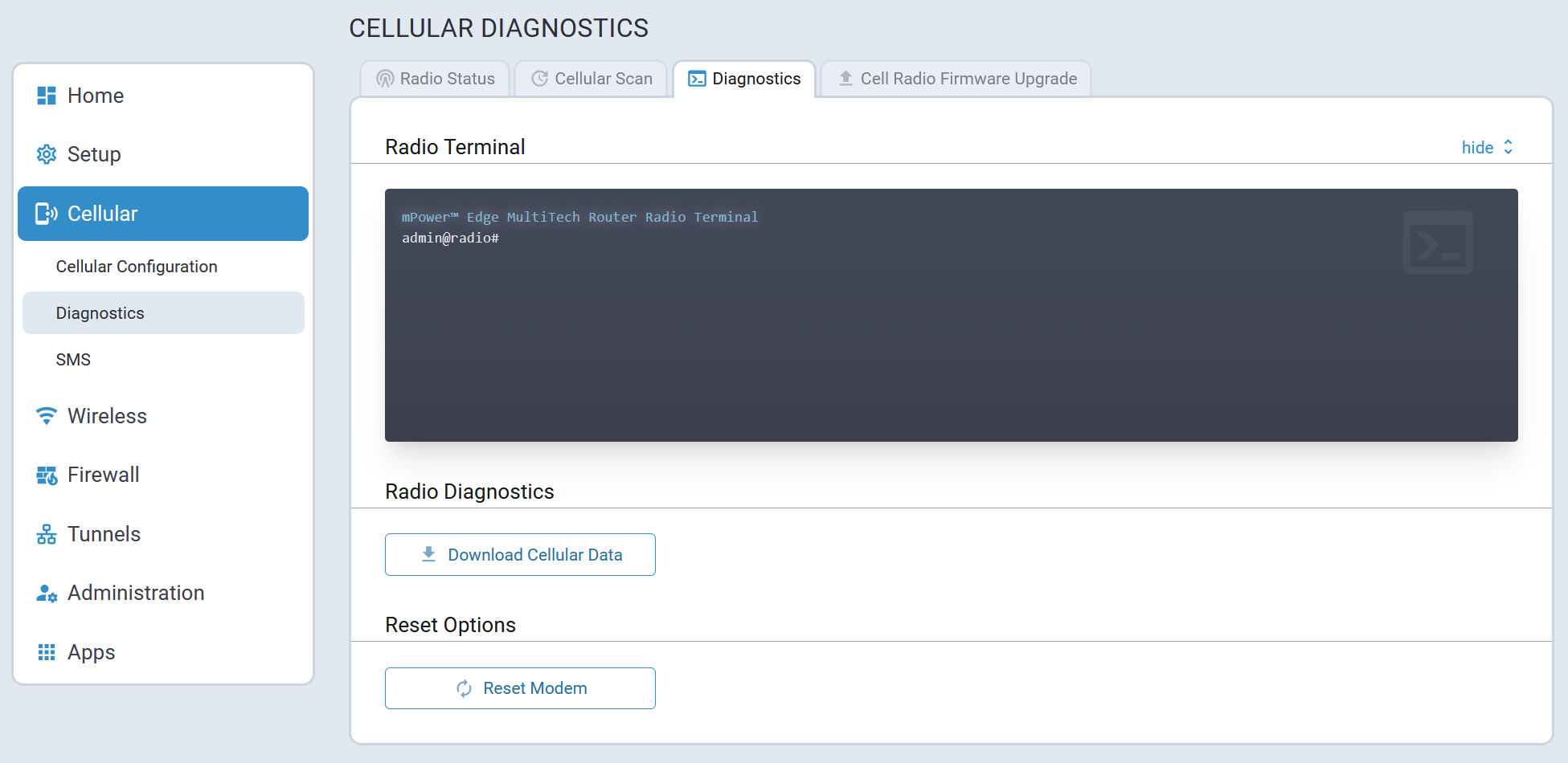
Cell Radio Firmware Upgrade Tab
The system allows users to perform a cellular radio firmware upgrade.
Because cell radio firmware upgrades are treated as critical operations, the device prevents reboot during the upgrade process. If the upgrade process remains active for more than an hour, the system alerts users, logs a possible hang, and then reboots safely.
A typical Cell Radio Firmware Upgrade tab is illustrated here:
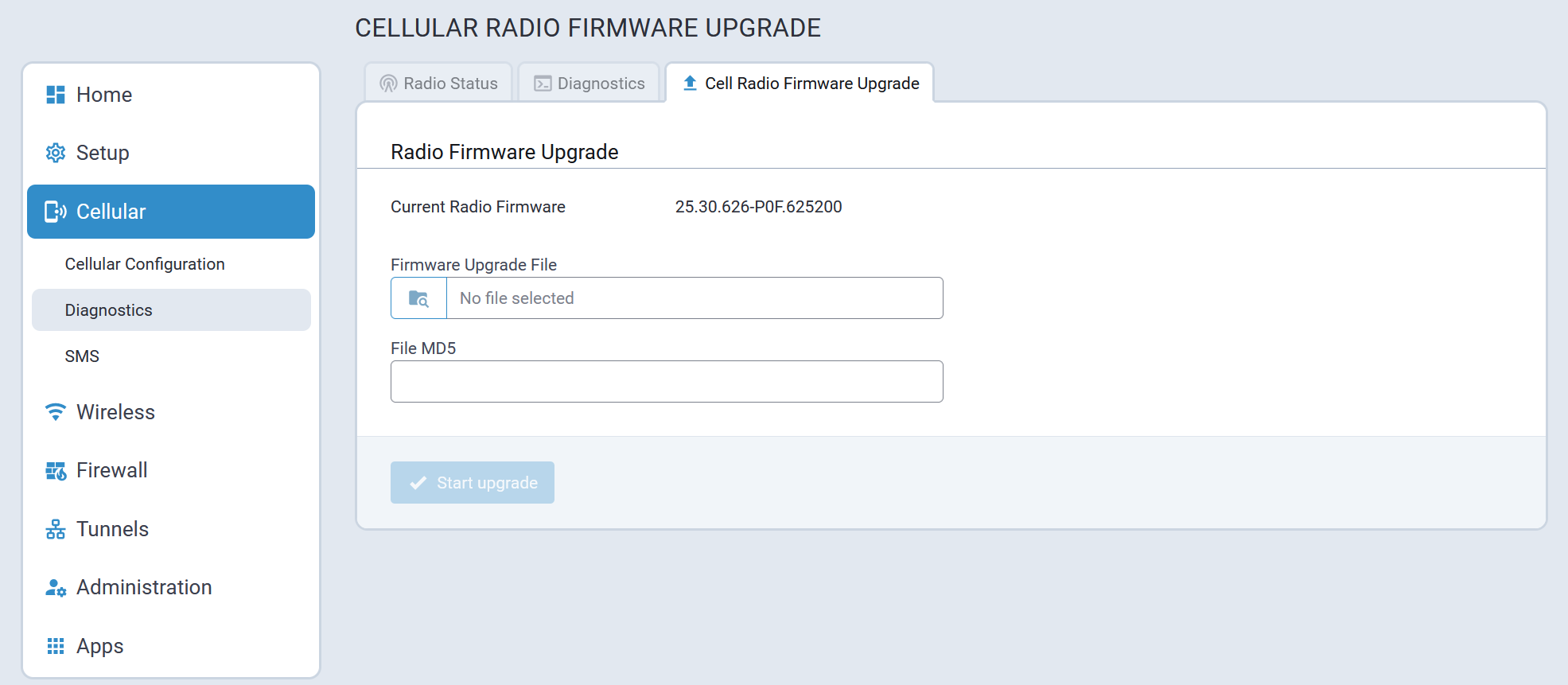
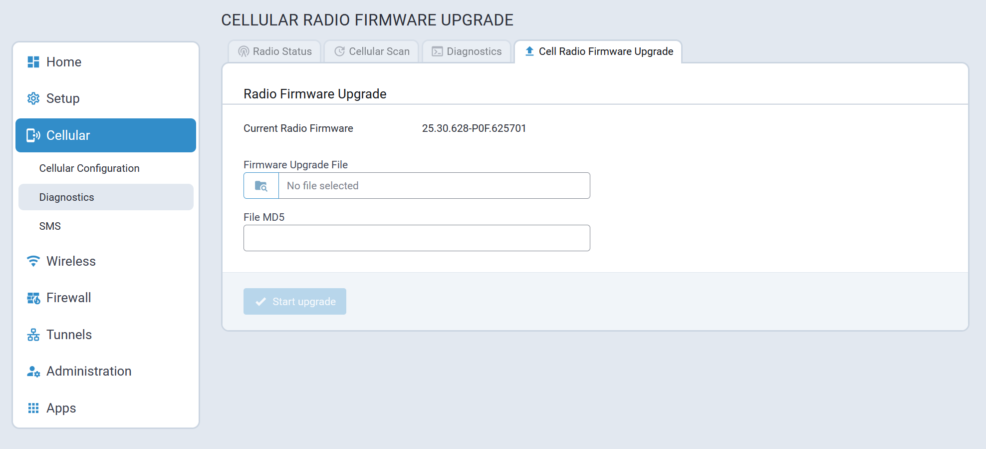
SMS
A typical SMS Configuration page is illustrated here:
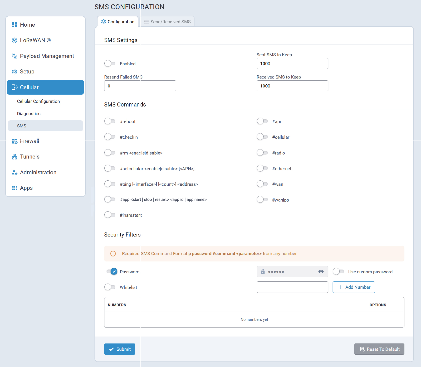
Configuration Tab
#setcellular#apn#cellular#radio
#wifi command
isn't available on devices that don't support WiFi.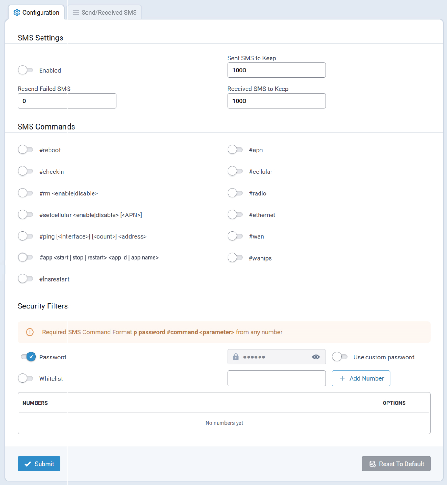
SMS Configuration Parameters
SMS configuration parameters are described in the following sections.
SMS Settings
| Parameter | Description |
|---|---|
| Enabled | Enables the SMS utilities required to send SMS via API and the Web Management interface. |
| Sent SMS to Keep | The total number of sent SMS messages to keep in the Conduit® AP 300's history. |
| Resend Failed SMS | The total number of resend attempts for SMS messages that fail to be sent. |
| Received SMS to Keep | The total number of received SMS messages to keep in the Conduit® AP 300's history. |
SMS Commands
The available SMS Commands for the Conduit® AP 300 are displayed in this section.
#setcellular#apn#cellular#radio
#wifi command
isn't available on devices that don't support WiFi.Review the table for detailed information about each command, which are all:
- Disabled by default.
- Required to be in the listed order.
For example:
#ping [<interface>] [<count>] <address> - Identified as required by arguments with angle brackets < >.
For example:
<address> - Identified as optional by arguments within square brackets [ ].
For example:
[<count>]
| SMS Command | Description |
|---|---|
#reboot |
Reboot the Conduit® AP 300. |
#checkin |
Check in to Device Manager |
#rm <enable | disable> |
Enable or disable remote management using Device Manager. |
#setcellular <enable | disable>
[<APN>] |
Enable or disable Cellular. To configure the Note: Not available when a Conduit® AP 300 is not equipped with a radio modem.
|
#ping [<interface>] [<count>]
<address> |
Ping a specified IP address or hostname using the following attributes:
|
#app <start | stop | restart> <app id | app
name> |
Starts, stops, or restarts a custom application identified by its
app id or app name that has been
installed on the Conduit® AP 300. |
#lnsrestart |
Upon reception, the Conduit® AP 300 restarts the LoRa network server |
#apn |
Retrieve the APN string.
Note: Not available
when a Conduit® AP 300 is not equipped with a
radio modem.
|
#cellular |
Retrieve the cellular connection status.
Note: Not available when a Conduit® AP 300 is not
equipped with a radio modem.
|
#radio |
Retrieve the radio status.
Note: Not available
when a Conduit® AP 300 is not equipped with a
radio modem.
|
#ethernet |
Retrieve the Ethernet interface configuration. |
#wan |
Retrieve the actual WAN transport and WAN priority configuration. |
#wifi |
Retrieve the following WiFi information:
|
#wanips |
Retrieve the IPv4 and IPv6 addresses that are currently assigned to existing WAN network interfaces. |
Security Filters
Security filters involve enabling a security filter password and whitelisting phone numbers to control SMS command execution and ensure only authorized users can execute SMS commands, enhancing system security. The key steps involved are:
- Enable Security Filter Password and Whitelist Phone Number: This ensures that only authorized devices can send commands.
- Use of Whitelisted Cellphones:
- Send messages with a password: For example,
p <password> #ping xxx.xxx.xxx.xxx. - Verify the cellphone receives the status of the ping via an SMS message.
- Messages sent without a password result in the command being ignored.
- Send messages with a password: For example,
- Use of Non-Whitelisted Cellphones:
- Messages sent with or without a password result in the command being ignored by the device.
Send/Received SMS Tab
A typical Send/Received SMS tab is illustrated here:
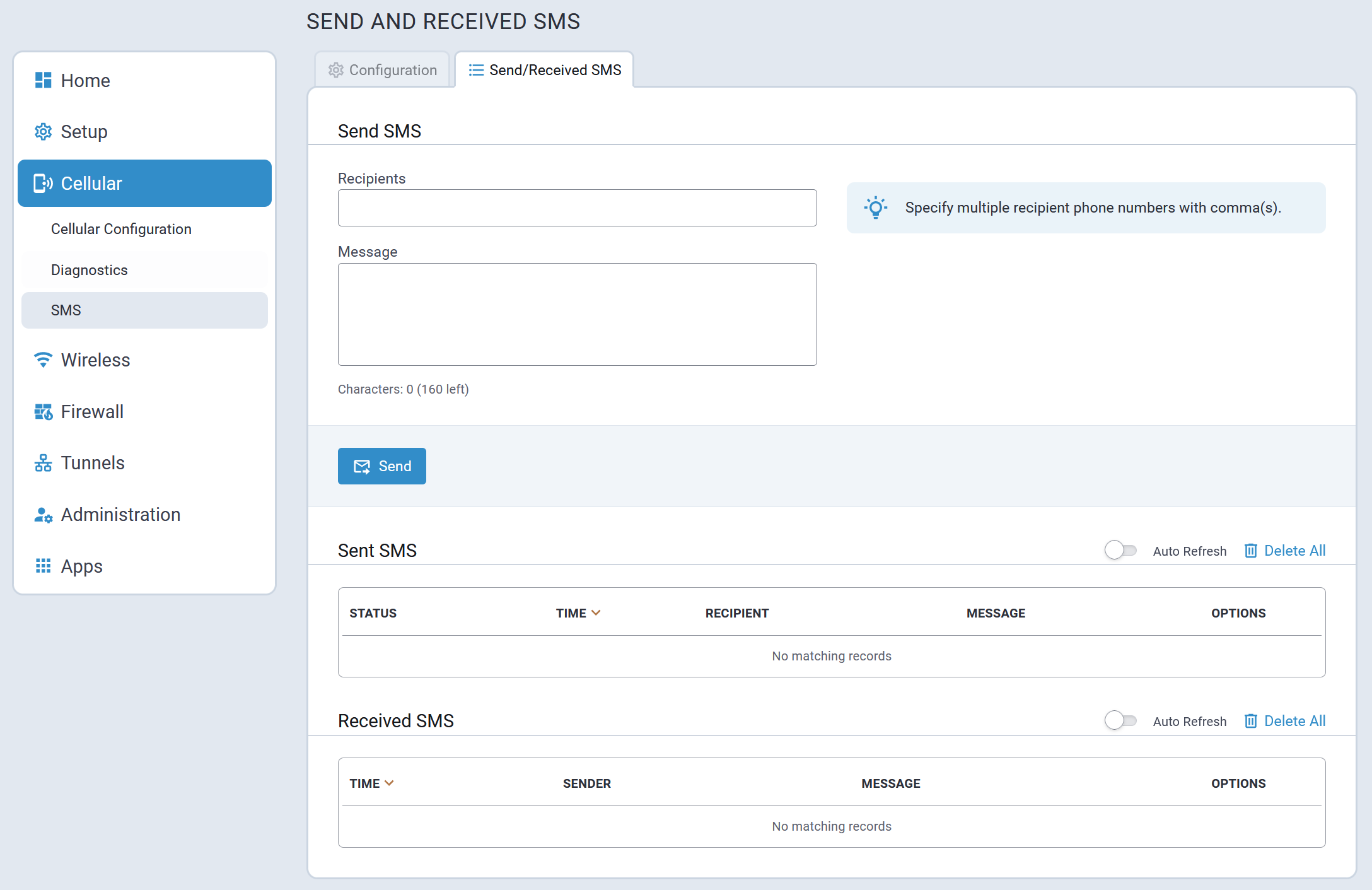
Wireless Menu
- As a Wi-Fi Access Point
- As a Wi-Fi as WAN client
- Concurrently as a Wi-Fi Access Point and Wi-Fi as WAN clientNote: The Conduit® AP 300's Wi-Fi module cannot use different bands or channels for its two functional parts. Therefore, the access point's frequency and channel settings will be the same as the Wi-Fi WAN network's.
Wi-Fi Configuration
A typical Wi-Fi Configuration page is illustrated here:
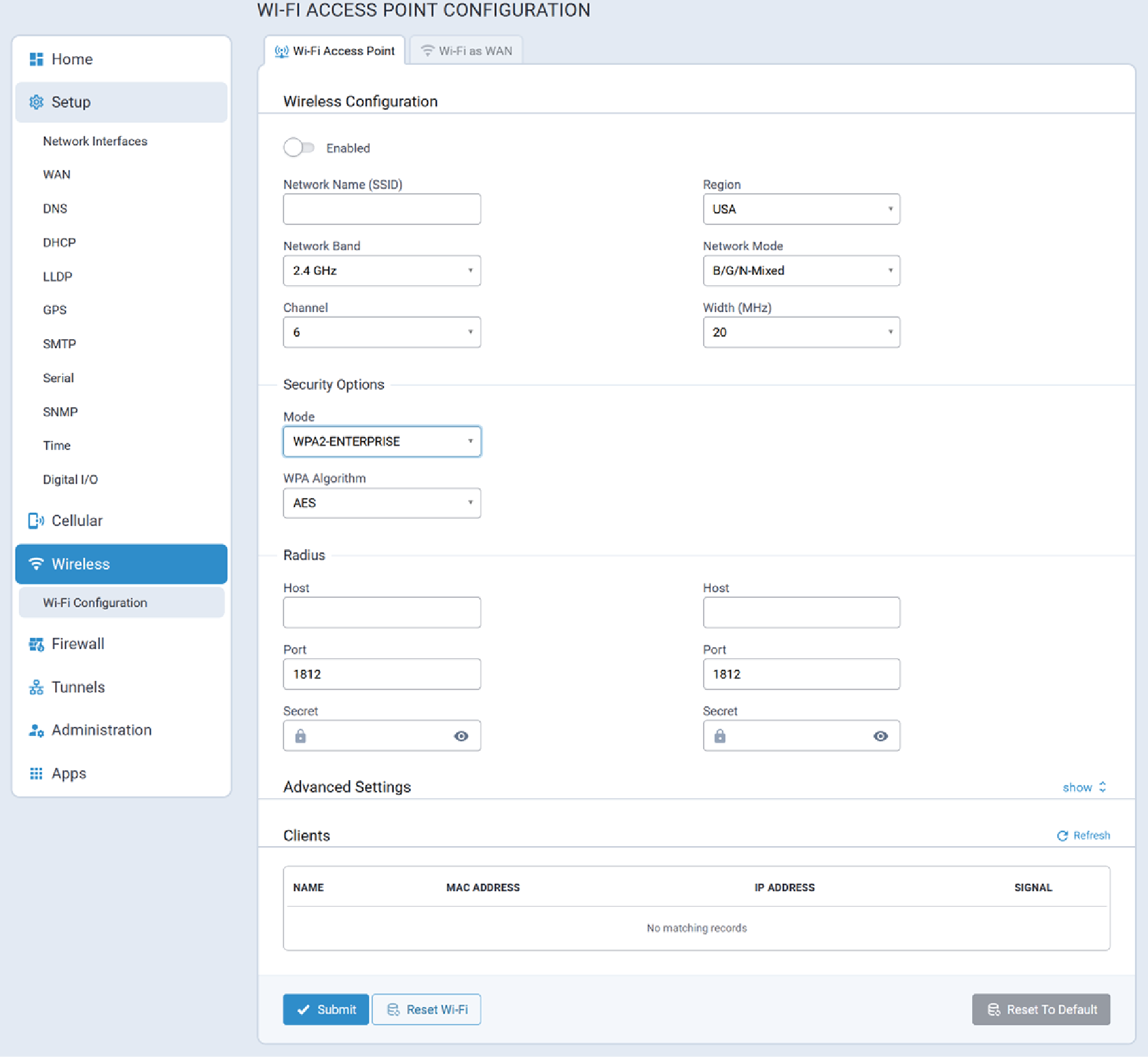
Wi-Fi Access Point Tab
Conduit® AP 300 can support up to 16 clients connected to the Wi-Fi Access Point.
Supported regions are limited to USA and Canada.
A typical Wi-Fi Access Point configuration page is illustrated here:
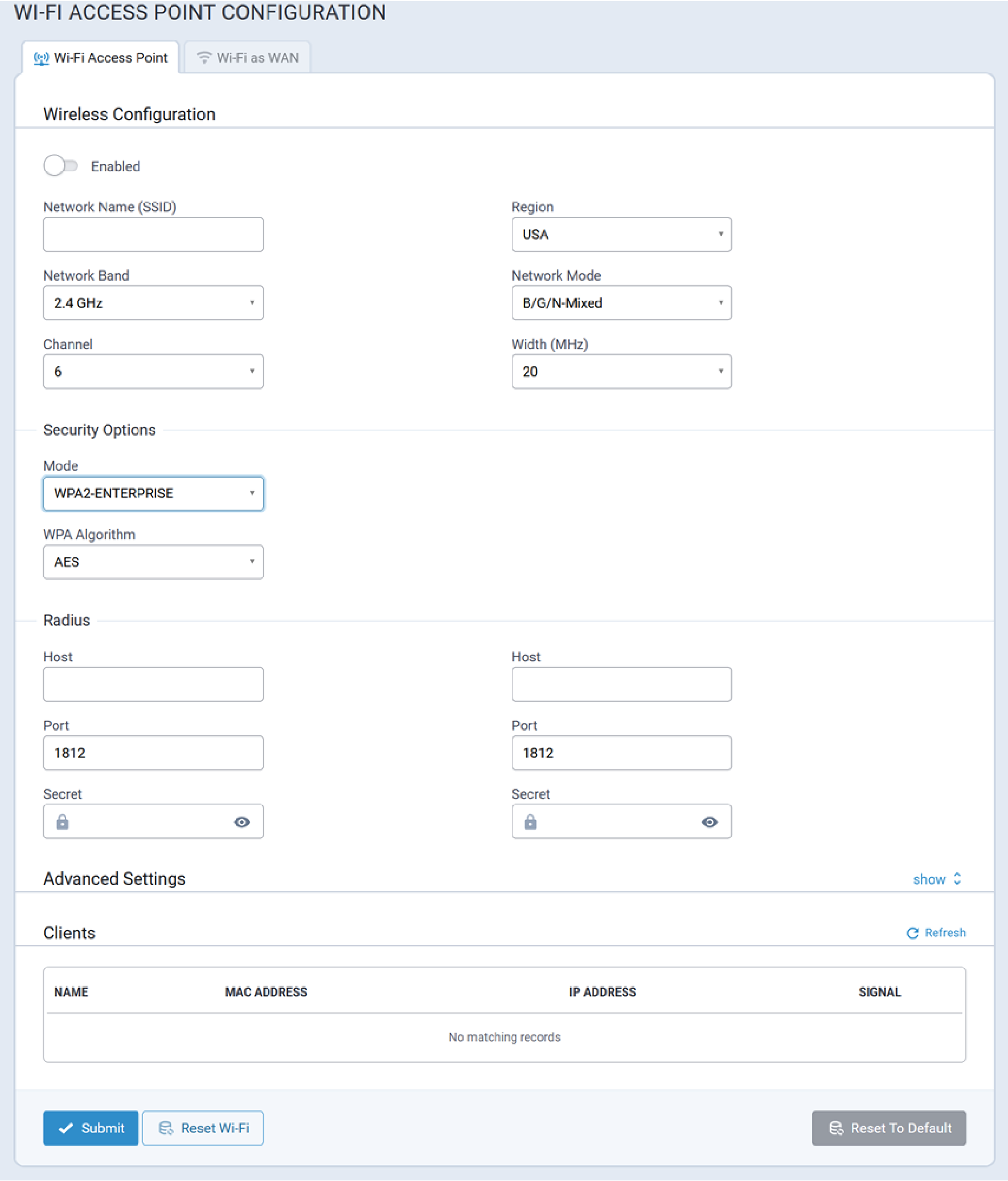
Wi-Fi Access Point Configuration Parameters
Wireless Configuration
| Parameter | Valid Values | Description |
|---|---|---|
| Enabled | Valid values are:
|
Enables/disables Wi-Fi Access Point mode. |
| Network Name (SSID) | User-specified | The user-specified name for the Wi-Fi network. |
| Region | Valid values are:
|
The region in which the Conduit® AP 300 is
operating. Note: When operating in concurrent
mode (i.e., both Wi-Fi Access Point and Wi-Fi as WAN are enabled,)
this parameter will be hidden. The Conduit® AP 300
will use Wi-Fi as WAN configuration information.
|
| Network Band | Valid values are:
|
The radio frequency over which the Conduit® AP 300
will communicate. Note: When operating in concurrent
mode (i.e., both Wi-Fi Access Point and Wi-Fi as WAN are enabled,)
this parameter will be hidden. The Conduit® AP 300
will use Wi-Fi as WAN configuration information.
|
| Network Mode | Valid values are:
|
Note: When operating in concurrent
mode (i.e., both Wi-Fi Access Point and Wi-Fi as WAN are enabled,)
this parameter will be hidden. The Conduit® AP 300
will use Wi-Fi as WAN configuration information.
|
| Channel | Valid values are:
|
The Wi-Fi channel over which the Conduit® AP 300
will communicate. Note: When operating in concurrent mode (i.e., both
Wi-Fi Access Point and Wi-Fi as WAN are enabled,) this parameter
will be hidden. The Conduit® AP 300 will use Wi-Fi
as WAN configuration information.
|
| Width (MHz) | Valid values are:
|
Note: When operating in concurrent
mode (i.e., both Wi-Fi Access Point and Wi-Fi as WAN are enabled,)
this parameter will be hidden. The Conduit® AP 300
will use Wi-Fi as WAN configuration information.
|
Security Options
| Parameter | Valid Values | Description |
|---|---|---|
| Mode | Valid values are:
|
Note: To configure Wi-Fi Enterprise security,
select WPA2-ENTERPRISE. The Radius server that will be
responsible for the authentication must also be configured.
|
| WPA Algorithm | Valid values are:
|
Radius
| Parameter | Valid Values | Description |
|---|---|---|
| Host | IP address | |
| Host | IP address | |
| Port | Port number | |
| Port | Port number | |
| Secret | Connection password | |
| Secret | Connection password |
Advanced Settings
To be provided.
Clients
To be provided.
Wi-Fi as WAN Tab
Typical Wi-Fi as WAN configuration values are illustrated here:
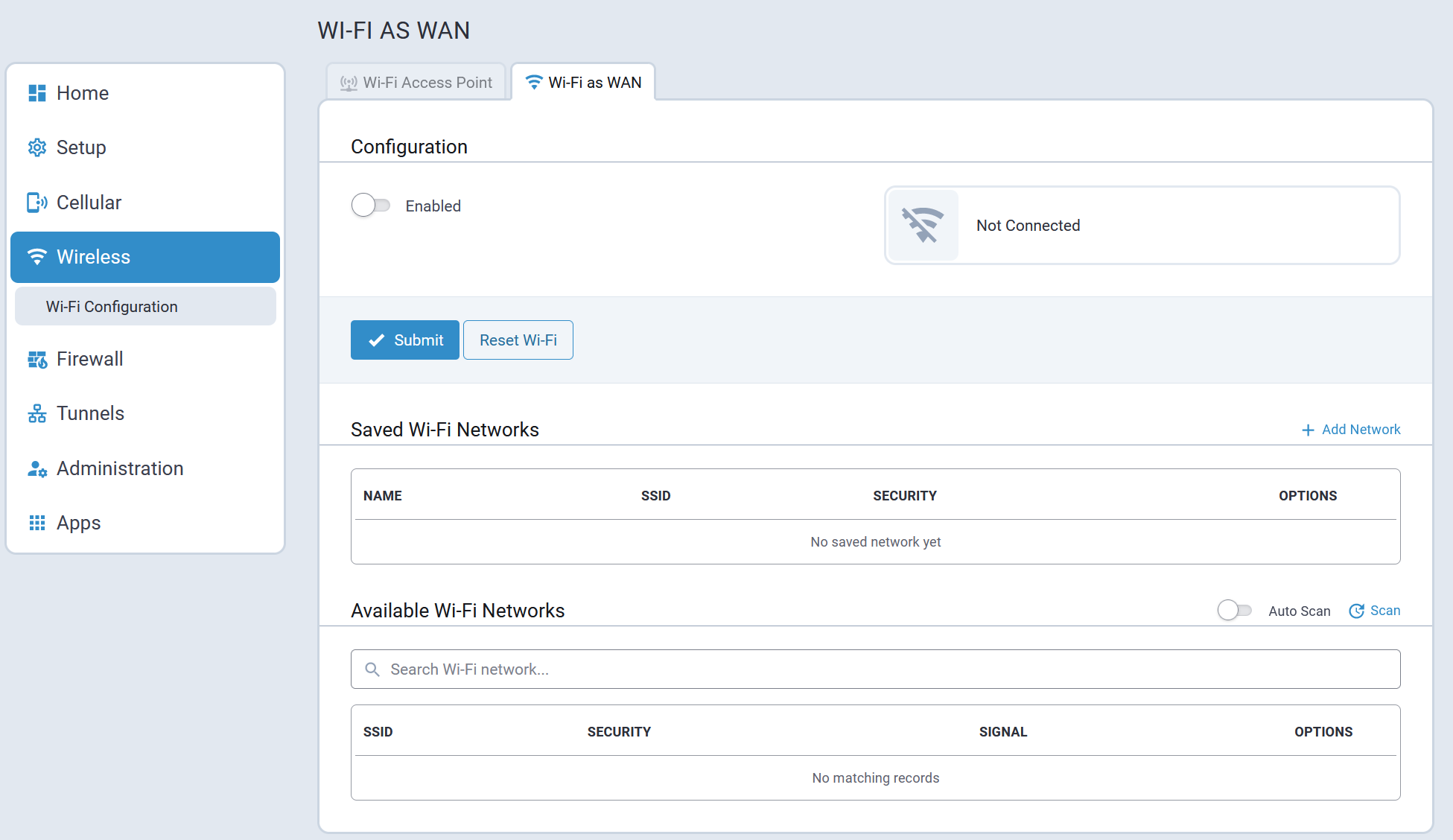
Wi-Fi as WAN Configuration Parameters
Configuration
Adjust the configuration parameters then click Submit. Click Reset Wi-Fi to clear any changes and reset the Wi-Fi as WAN configuration to defaults.
| Parameter | Default | Valid Values | Description |
|---|---|---|---|
| WiFi Connection | Enabled | Valid values are:
|
Enables/disables Wi-Fi as WAN mode. |
| Connection | Not Connected | Valid values are:
|
Shows the Wi-Fi connection status. |
Automatic Roaming
Wi-Fi roaming enhances connection reliability in multi-access point environments by automatically transitioning to the strongest available signal. This feature is disabled by default.
The Roaming Aggressiveness setting controls the switching behavior between access points:
- AGGRESSIVE - Switches quickly to stronger signals but may cause brief disconnections
- BALANCED (default) - Provides optimal balance between signal strength and connection stability
- PASSIVE - Maintains current connection longer, potentially remaining on weaker signals
| Parameter | Default | Valid Values | Description |
|---|---|---|---|
| Automatic Roaming | Enabled | Valid values are:
|
Enables/disables automatic roaming, which enhances connection reliability in multi-access point environments by automatically transitioning to the strongest available signal. This feature is disabled by default. |
| Roaming Aggressiveness | Balanced | Valid values are:
|
Sets the aggressiveness level for the switching behavior between access points when you enable automatic roaming. |
Saved Wi-Fi Networks
- Network Name
- Hidden Network
- SSID
- Security Mode
- Authentication Method
- Username
- Password
Available Wi-Fi Networks
- SSID
- Security
- Signal
Firewall Menu
The device's firewall enforces a set of rules that determine how incoming and outgoing packets are handled. By default, all outbound traffic originating from the LAN is allowed to pass through the firewall, and all inbound traffic originating from external networks is dropped. This effectively creates a protective barrier between the LAN and all other networks.
The following parameters are configured under the Firewall menu:
- Settings
- Trusted IP
- Static Routes
Firewall Rules and Port Forwarding
Firewall Rules and Port Forwarding are performed using nftables.
To print Firewall Rules in the device console use nft list ruleset.
Settings
Firewall Rules and Port Forwarding configuration and status is performed on the following tabs:
- Settings
- Status
Settings Tab
Typical firewall rule configuration settings are illustrated here:
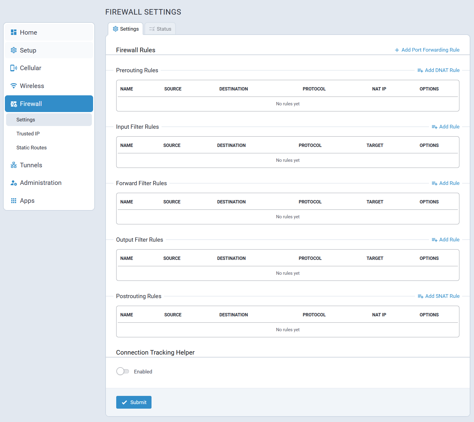
Port Forwarding
The Add Port Forwarding Rule option allows users to create a Port Forwarding rule which comprises two separate firewall rules:
- A prerouting rule
- A forward filter rule
As soon as a user selects Add Port Forwarding Rule, the system automatically creates two separate rules.
If changes to the port forwarding rules are required, each of the corresponding rules should be updated individually. Alternatively, the incorrect rules can be deleted and a new port forwarding rule created by selecting the Add Port Forwarding Rule button.
Typical port forwarding configuration settings are illustrated here:
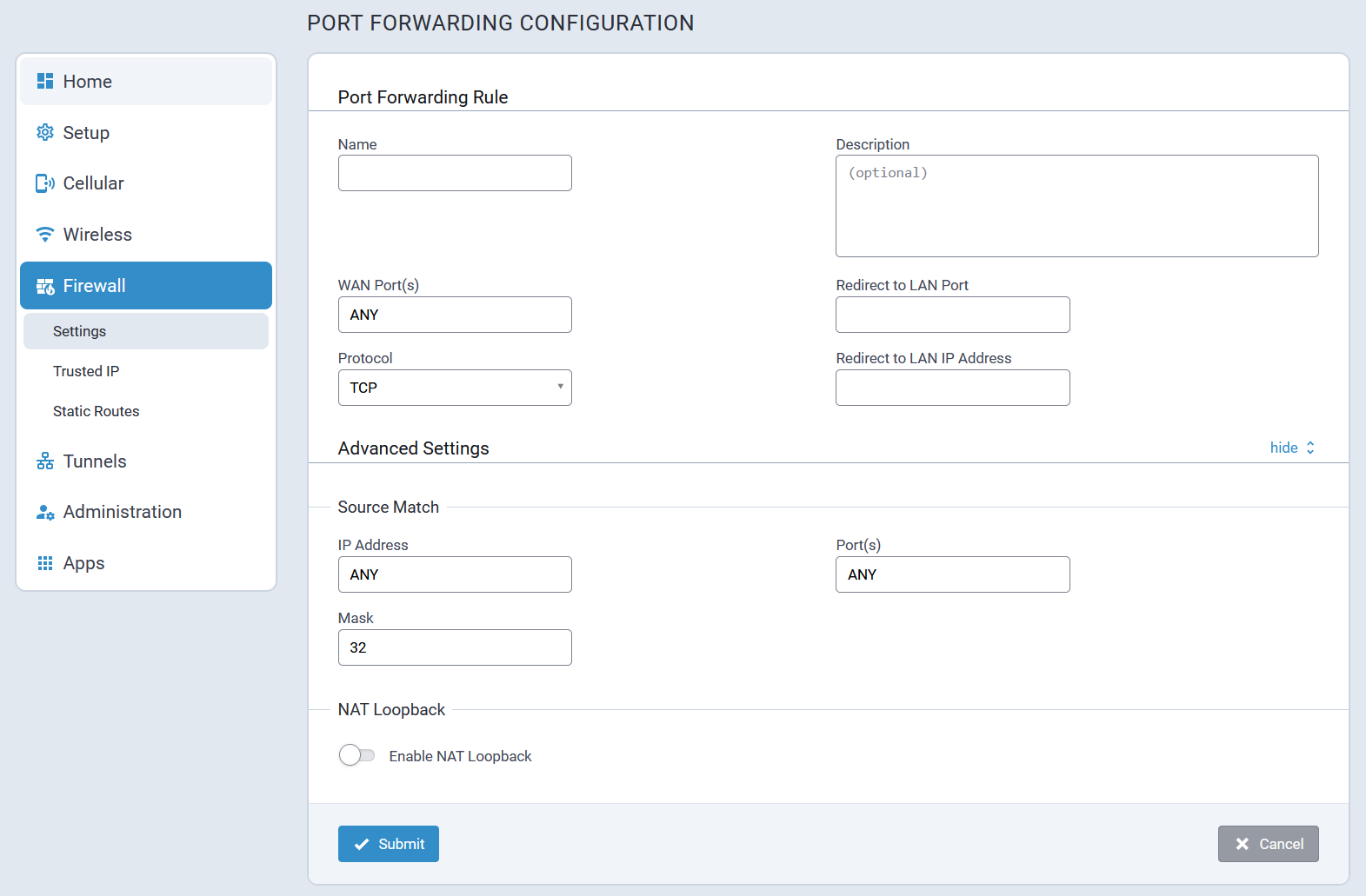
Status Tab
The Firewall Status allows users to review the Firewall rules that are currently being applied within the system.
When a user selects Download, the system creates an archive with a firewall-ruleset.log file.
A typical firewall Status tab is illustrated here:
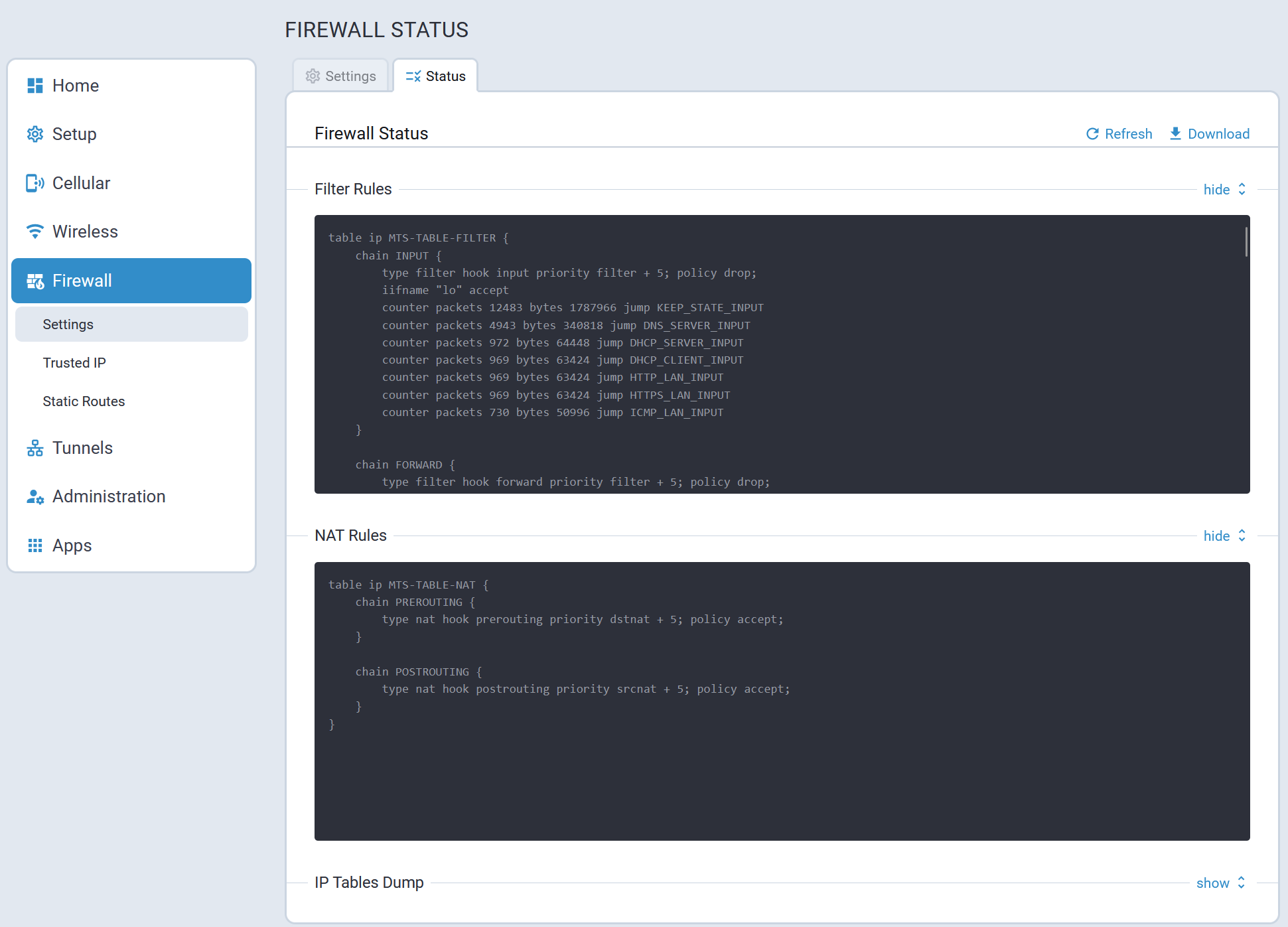
Trusted IP
Trusted IP is a simplified interface to create nftables rules to allow or block specific IPs, IP ranges, or subnets. This feature allows users to create whitelists (which are allowed or trusted IPs) or black lists (which are blocked or unwanted IPs). You can add, edit, and delete IP addresses as needed.
- If you select White List as Trusted IP Mode and do not set any IP range, no traffic will be allowed.
- If you select Black List as Trusted IP Mode and do not set any IP range, all traffic will be allowed.
Typical Trusted IP settings are illustrated here:
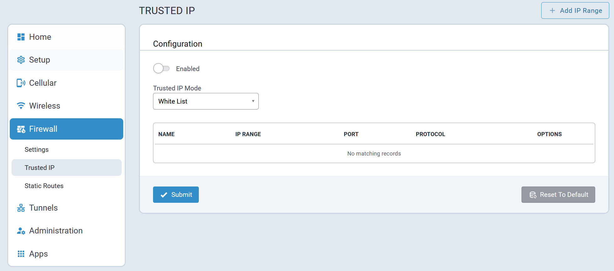
Static Routes
Configuring static routes adds persistent routes to remote devices that are automatically recreated when the Conduit® AP 300 is rebooted.
A typical Static Route settings page is illustrated here:
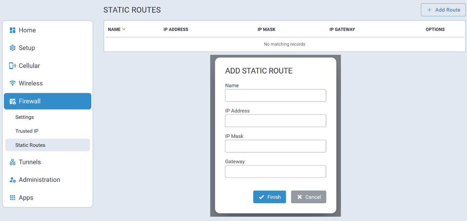
Tunnels Menu
Tunneling allows the use of a public network to convey data on behalf of two remote private networks. It is also a way to transform data frames to allow them to pass networks with incompatible address spaces or even incompatible protocols.
The Conduit® AP 300 supports the following tunnel mechanisms:
- GRE Tunnels
- IPSec Tunnels
- OpenVPN Tunnels
GRE Tunnels
Generic Routing Encapsulation (GRE) is a tunneling mechanism that uses IP as the transport protocol and can be used for carrying many different passenger protocols.
The tunnels behave as virtual point-to-point links that have two endpoints identified by the tunnel source and tunnel destination addresses at each endpoint. Configuring a GRE tunnel involves creating a tunnel interface, which is a logical interface, then configuring the tunnel endpoints for the tunnel interface.
GRE Configuration Tab
A typical GRE Configuration page is illustrated here:
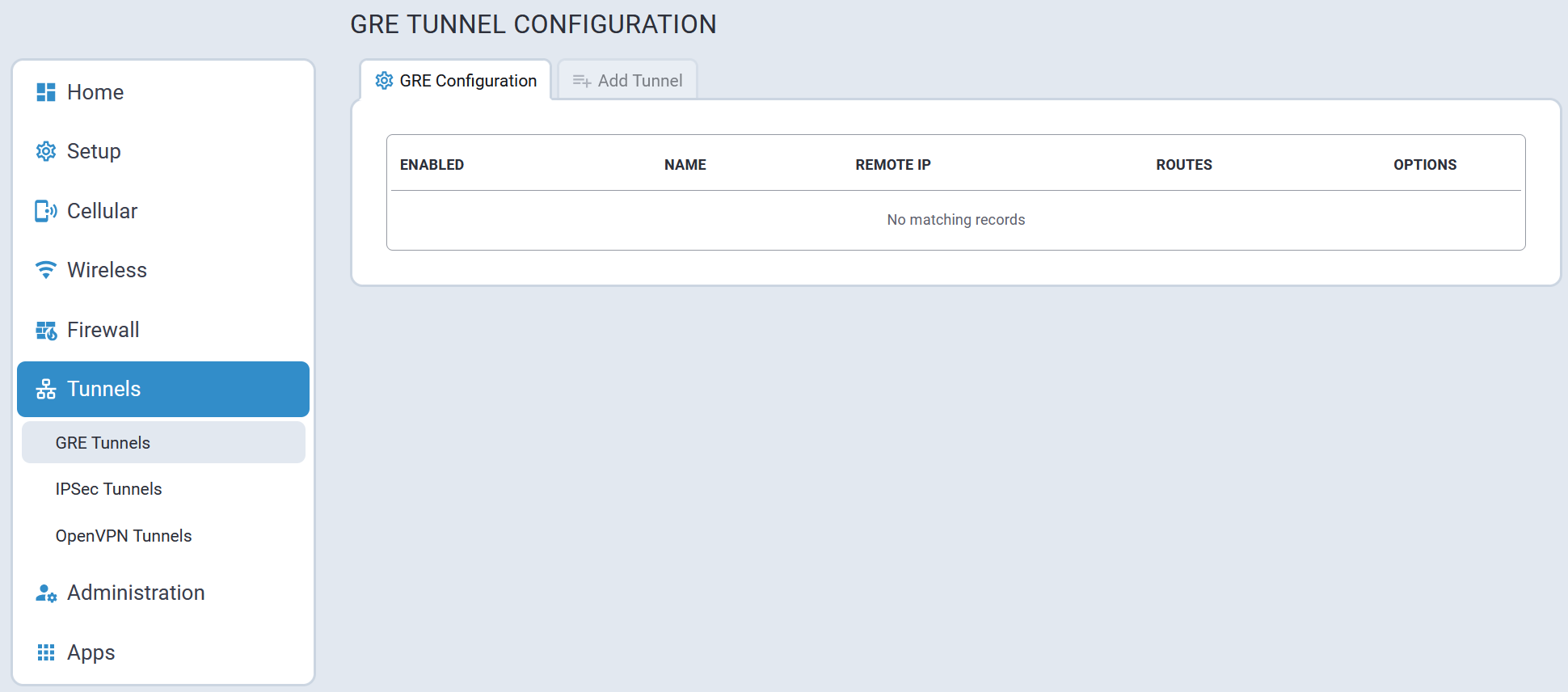
Add Tunnel Tab
To add a GRE tunnel, navigate to the Add Tunnel tab. Once all parameters have been configured, select Submit.
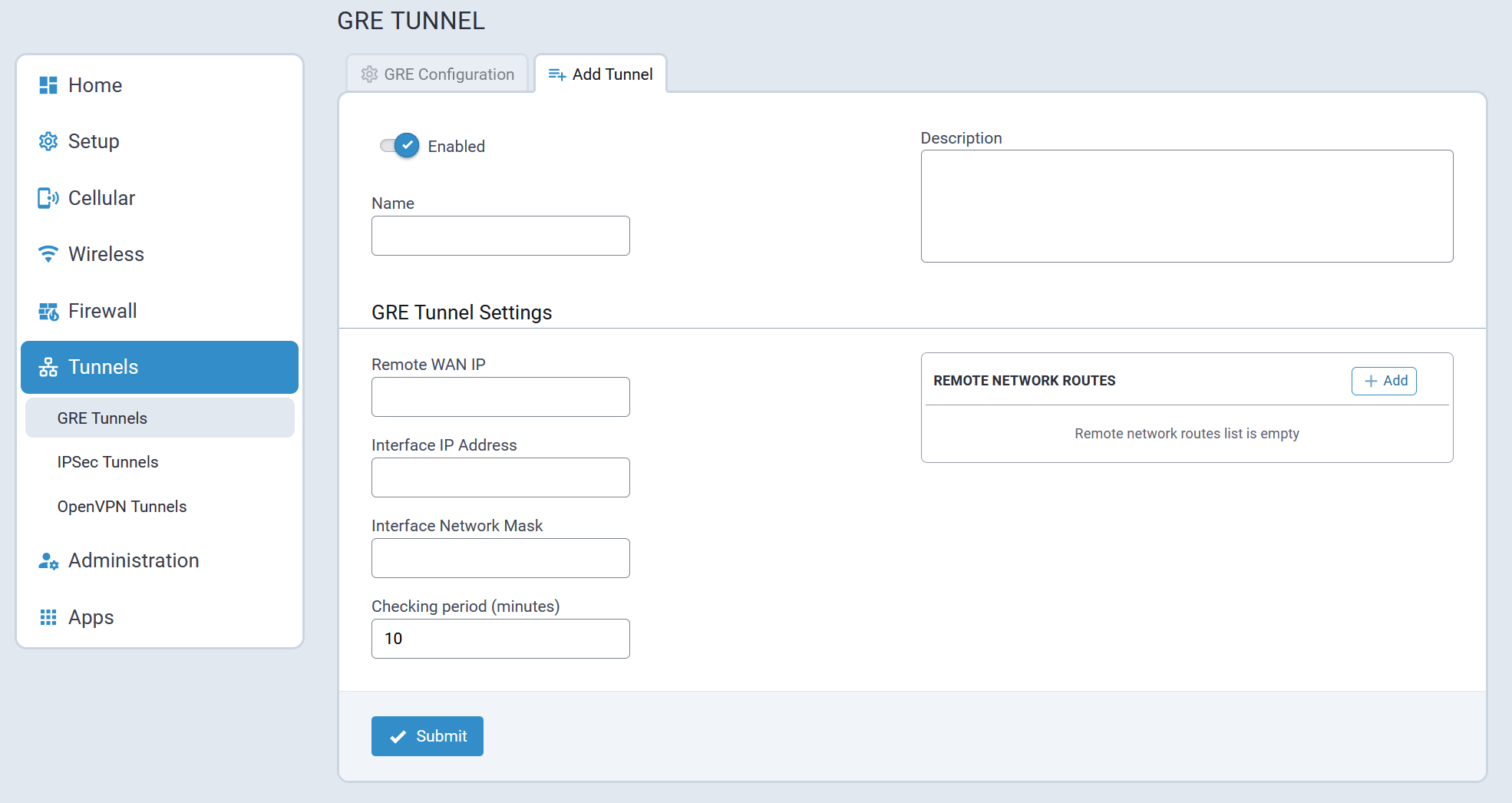
IPSec Tunnels
The device supports site-to-site VPNs via IPsec tunnels for secure network-to-network communication. Both tunnel endpoints should have static public IP addresses and must be able to agree on the encryption and authentication methods to use.
Setting up an IPsec tunnel is a two-stage negotiation process.
- The first stage negotiates how the key exchange is protected.
- The second stage negotiates how the data passing through the tunnel is protected.
For endpoints that do not have public static IP addresses, additional options may help such as NAT Traversal and Aggressive Mode.
By default, based on the encryption method chosen, the device negotiates ISAKMP hash and group policies from a default set of secure algorithms with no known vulnerabilities. This allows flexibility in establishing connections with remote endpoints. There is an ADVANCED mode that provides a way to specify a strict set of algorithms to use per phase, limiting the remote endpoint's negotiation options.
The default Encryption Method is: AES-128.
The default set of DH Group Algorithms is:
- DH2(1024-bit)
- DH5(1536-bit)
- DH14(2048-bit)
- DH15(3072-bit)
- DH16(4096-bit)
- DH17(6144-bit)
- DH18(8192-bit)
- DH22(1024-bit)
- DH23(2048-bit)
- DH24(2048-bit)
There is the option to add multiple local and remote networks. These additional subnets can provide more complexity, flexibility, efficiency, and redundancy to the VPN. Using multiple networks allows different endpoints in different LAN subnets to securely communicate through the same tunnel. Users do not have to configure an additional tunnel for those subnets saving time and effort.
IPSec Configuration Tab
A typical IPSec Configuration tab is illustrated here:
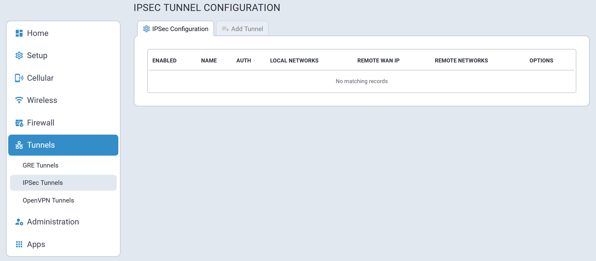
Add Tunnel Tab
To add an IPSec tunnel, navigate to the Add Tunnel tab. Once all parameters have been configured, select Submit.
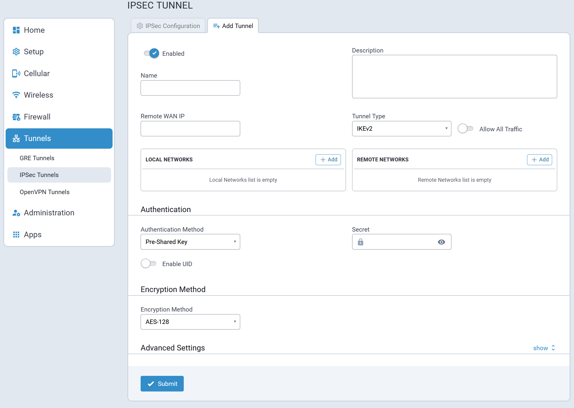
Configuration Parameters
Refer to the following table for information about each IPSec configuration parameter.
| Parameter | Description |
|---|---|
| IPSec Tunnel | |
| Name | Name used to identify the IPsec tunnel in configurations and logs. |
| Description | Optional text to describe the IPsec tunnel. This description shows up in the UI while hovering over the summary of an IPsec tunnel. |
| IPSec Remote Tunnel Endpoint | |
| Remote WAN IP | External IP address of the remote tunnel endpoint. The remote device is typically a router. |
| Remote Network Route | This field is used in conjunction with the Remote Network Mask field and describes the remote endpoint's subnet. This is used to identify packets that are routed over the tunnel to the remote network. |
| Remote Network Mask | This field is used in conjunction with the Remote Network Route field, to describe the remote endpoint's subnet. It identifies packets that are routed over the tunnel to the remote network. |
| Tunnel Type | Internet Key Exchange (IKE) for host-to-host, host-to-subnet, or subnet-to-subnet tunnels. Choose from IKE or IKEv2. |
| IPsec Tunnel: IKE | |
| Authentication Method | Choose between Pre-Shared Key or RSA Signatures. Authentication is performed using secret pre-shared keys and hashing algorithms (like SHA1 MD5) or RSA signatures (you provide the CA Certificate, Local RSA Certificate, and Local RSA Private Key in .pem format). If you check Enable UID, then Local ID and Remote ID become available as options. |
| Pre-Shared Key | Authentication is performed using a secret pre-shared key and hashing algorithms on both sides. |
| Secret | Secret key that is known by both endpoints. |
| Encryption Method | IKE encryption algorithm used for the connection (phase 1 - ISAKMP SA). Based off of phase 1, a secure set of defaults are used for phase 2, unless the Advanced option is used, in which case, all components of both phases 1 and 2 are specified by the user. |
| RSA Signatures | Authentication is performed using digital RSA signatures. |
| CA Certificate | Certificate Authority certificate used to verify the remote endpoint's certificate. |
| Local RSA Certificate | Certificate the local endpoint uses during Phase 1 Authentication. |
| Local RSA Private Key | The private key that the local endpoint uses during Phase 1 Authentication. |
| Encryption Method1 | Choose an Encryption Method from the following list: AES-128, AES-192, AES-256, or ADVANCED. IKE encryption algorithm is used for the connection (phase 1 - ISAKMP SA). Based off of phase 1, a secure set of defaults are used for phase 2, unless the Advanced option is used, in which case, all components of both phases 1 and 2 are specified by the user. |
| Phase 1 Encryption1 |
If Advanced is selected for Encryption Method, select Phase 1 Encryption from the drop-down: AES-128, AES-192, AES-256, or ANY AES. |
| Phase 1 Authentication1 |
If Advanced is selected for Encryption Method, select Phase 1 Authentication from the drop-down: SHA-2, SHA2-256, SHA2-384, SHA2-512, or ANY. |
| Phase 1 Key Group1 |
If Advanced is selected for Encryption Method, select the Phase 1 Key Group from the drop-down: DH2 (1024-bit), DH5 (1536-bit), D14 (2048-bit), DH15 (3072-bit), DH16 (4096-bit), DH17 (6144-bit), DH18 (8192-bit), DH22 (1024-bit), DH23 (2048-bit), DH24 (2048-bit), and ANY. |
| Phase 2 Encryption1 |
If Advanced is selected for Encryption Method, select Phase 2 Encryption from the drop-drown: AES-128, AES-192, AES-256, ANY AES, or ANY. |
| Phase 2 Authentication1 |
If Advanced is selected for Encryption Method, select Phase 2 Authentication from the drop-drown: SHA-2, SHA2-256, SHA2-384, SHA2-512, or ANY. |
| Phase 2 Key Group1 |
If Advanced is selected for Encryption Method, select the Phase 2 Key Group from the drop-down: DH2 (1024-bit), DH5 (1536-bit), D14 (2048-bit), DH15 (3072-bit), DH16 (4096-bit), DH17 (6144-bit), DH18 (8192-bit), DH22 (1024-bit), DH23 (2048-bit), DH24 (2048-bit), and ANY. |
| Enable UID | Unique Identifier String to enable the Local ID and Remote ID fields. |
| Local ID | String Identifier for the local security gateway (optional) |
| Remote ID | String Identifier for the remote security gateway (optional) |
| IPSec Tunnel: Advanced | |
| IKE Lifetime | Duration for which the ISAKMP SA exists from successful negotiation to expiration. |
| Key Life | Duration for which the IPsec SA exists from successful negotiation to expiration. |
| Max Retries | Number of retry attempts for establishing the IPsec tunnel. Enter zero for unlimited retries. |
| Checking Period |
Timeout interval in minutes. If Remote WAN IP address is a hostname that can be resolved by DynDNS, the hostname will be resolved at the set interval. Recommended for dynamic IP addresses. |
| Compression | Enable IPComp. This protocol increases the overall communication performance by compressing the datagrams. Compression requires greater CPU processing. |
| Aggressive Mode | Whether to allow a less secure mode that exchanges identification in plain text. This may be used for establishing tunnels where one or more endpoints have a dynamic public IP address. Although this mode is faster to negotiate phase 1, the authentication hash is transmitted unencrypted. You can capture the hash and start a dictionary or use brute force attacks to recover the PSK. |
1 For mPower 5.3 and higher, deprecated encryption and hash algorithms are not available for creating new tunnels. But old tunnels that were created in 5.2 or lower will retain the deprecated settings unless changed. Those deprecated settings include: 3DES, ANY, MD5, and SHA-1.
OpenVPN Tunnels
OpenVPN is an open-source software application that implements virtual private network (VPN) techniques for creating secure point-to-point or site-to-site connections in routed or bridged configurations and remote access facilities.
To use OpenVPN, install an OpenVPN application along with an easy-rsa tool and configure OpenVPN on your computer. Then, generate the certificates for the OpenVPN server and client before configuring the device.
To configure OpenVPN client and server on this device the following files are required:
- CA PEM file or CA certificate (.crt)
- Diffie Hellman PEM file (.pem)
- Server Certificate to be used by the device endpoint (.crt)
- Server/Client Key to be used by the device endpoint (.key)
- When you configure OpenVPN server and client, make sure both sides use the same settings and certificates.
- For mPower 5.3 and higher, some encryption and hash configurations are deprecated and
not available for creating new tunnels. Any tunnels created in 5.2 or lower will retain
the deprecated settings unless changed.
- Deprecated settings for hash algorithms include: MD4, MD5, RSA-MD4, RSA-MD5, and SHA-1.
- Deprecated settings for encryptions ciphers include: BF-CBC, CAST5-CBC, DES-CBC, DES-EDE-CBC, DES-EDE3-CBC, DESX-CBC, IDEA-CBC, RC2-40-CBC, RC2-64-CBC, and RC2-CBC.
- Deprecated setting for Minimum TLS version is 1.1.
- Some encryption and hash configurations are too weak and NOT supported at all in mPower 5.3 or higher.
These settings do not function when performing an upgrade to mPower 5.3. The system provides a warning message during upgrade and replaces them with Default. The following TLS cipher suites are not supported: TLS-DHE-RSA-WITH-CAMELLIA-256-CBC-SHA and TLS-DHE-RSA-WITH-CAMELLIA-128-CBC-SHA. Also, the following hash algorithms are not supported: DSA, DSA-SHA, DSA-SHA1, DSA-SHA1-old, ECDSA-with-SHA1, RSA-SHA, RSA-SHA1-2, and SHA.
OpenVPN Configuration Tab
A typical OpenVPN Configuration page is illustrated here:
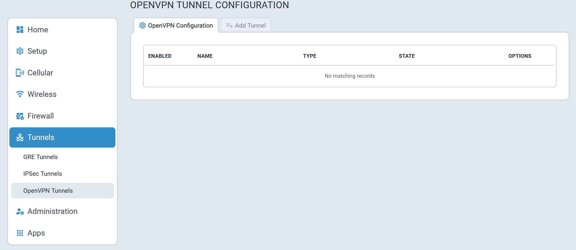
Add Tunnel Tab
To add a OpenVPN tunnel, navigate to the Add Tunnel tab. Once all parameters have been configured, select Submit.
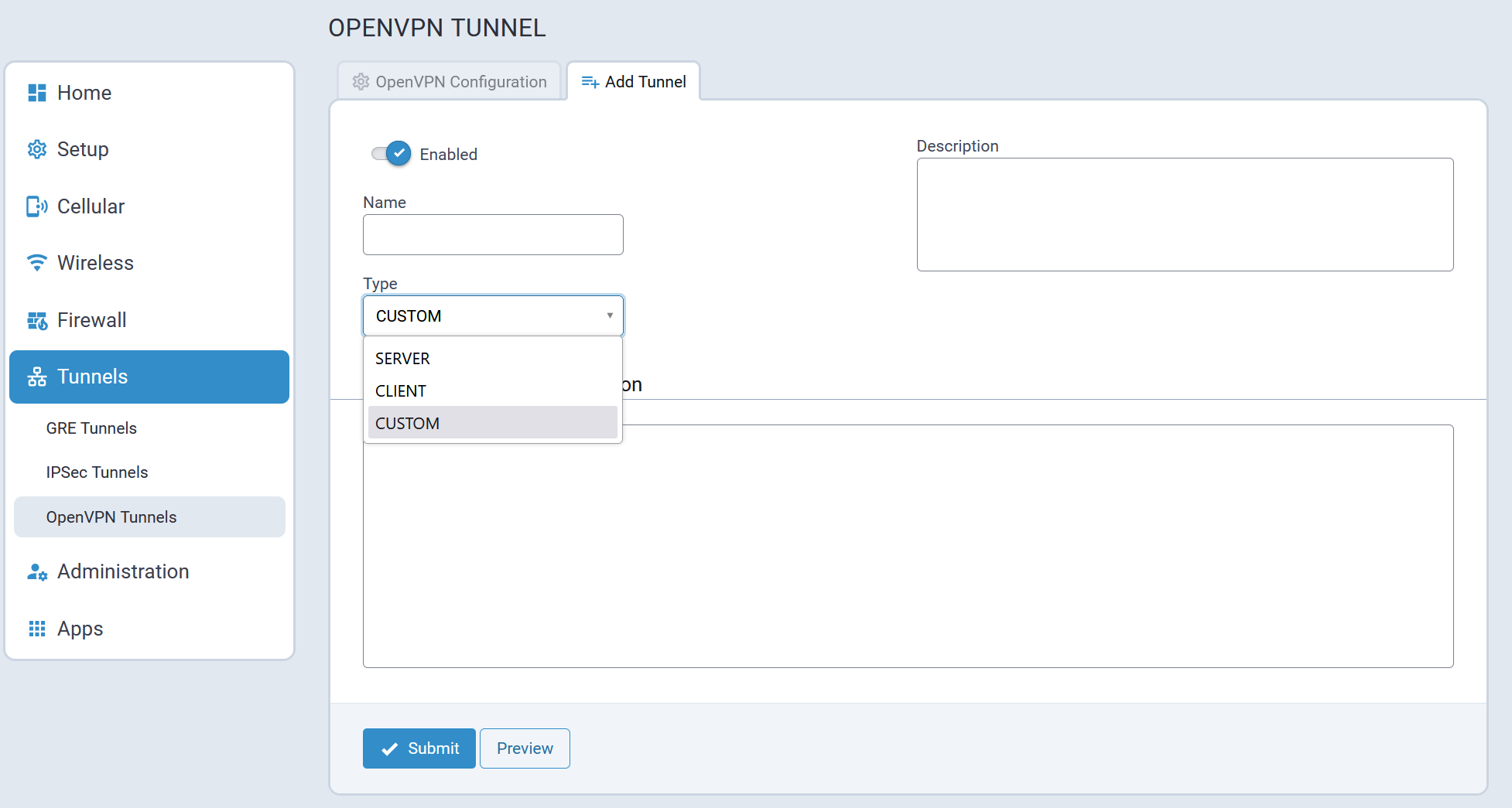
Configuration 1: OpenVPN Tunnel with TLS Authorization Mode (Device only)
This first configuration establishes the OpenVPN Tunnel connection from a device client to a device server using TLS as Authorization Mode. This involves adding and configuring both OpenVPN Server and Client sides within the device UI.
To add an OpenVPN Server using TLS:
- Go to Tunnels > OpenVPN Tunnels > OpenVPN Tunnel Configuration.
- Select Add Tunnel.
- Enter the Name.
- Select the Type as SERVER from the dropdown.
- You can also enter an optional Description.
- Under OpenVPN Tunnel Configuration, enter the following fields (using TLS as
Authorization Mode):
- Interface Type as TUN from the dropdown.
- Authorization Mode as TLS from the dropdown.
- Protocol as UDP.
- VPN Subnet.
- Port number.
- VPN Netmask.
- LZO Compression as ADAPTIVE from the dropdown.
- Hash Algorithm as DEFAULT.
- NCP (Negotiable Crypto Parameters) as DEFAULT.
- Min. TLS Version as 1.2.
- TLS Cipher Suite as DEFAULT.
- Enter the contents of the following files generated from the easy-rsa tool.
You can copy and paste this content from the certificate files after opening from a
text editor like Notepad (all required):
- CA PEM (.crt)
- Diffie Hellman PEM (.pem)
- Server Certificate PEM (.crt)
- Server Key PEM (.key)
Note: Use the same CA PEM certificate and parameters as the server for the OpenVPN clients.
- Remote Network Routes create a route from the server network to the client
network. This allows the server to get access to the client’s network. In the OpenVPN
Tunnel Network Routes, select Add:
- Enter the Remote Network Route (should be the client subnet). For example, if the client IP address is 192.168.3.1, enter 192.168.3.0.
- Enter the Remote Network Mask (usually 255.255.255.0).
- You may enter Gateway (optional).
- Select Add.
- The system displays your recently-added Push Route with the client subnet (remote network route + mask).
- Push Routes create a route from client’s network to the server’s network. This
allows clients to get access to the server’s network. Under Push Routes:
- Select Client To Client box if you want this optional feature (this establishes a connection between multiple clients that are connected to the server).
- In the Push Network Route, select Add.
- In the dialog box, enter the Remote Network Route (same address as the server subnet above).
- Enter the Remote Network Mask (same as above).
- Optional: You may enter Gateway.
- Select Add. Note: If you use Static Key Authorization Mode, the Push Routes do not work.
- The system displays your recently-added Push Route with the client subnet (remote network route + mask).
- Select Preview to view the tunnel configuration.
- Select Submit.
- Select Save and Apply to save your changes
To add an OpenVPN Client using TLS:
- Go to Tunnels > OpenVPN Tunnels > OpenVPN Tunnel Configuration.
- Select Add Tunnel.
- Enter the Name of the tunnel.
- Select the Type as CLIENT from the dropdown.
- Optional: Enter a Description.
- Under OpenVPN Tunnel Configuration, enter the following fields (using TLS as
Authorization Mode):
- Interface Type as TUN from the dropdown.
- Authorization Mode as TLS from the dropdown.
- Protocol as UDP.
- Remote Host (server public IP address).
- Remote Port number.
- LZO Compression as ADAPTIVE from the dropdown.
- Hash Algorithm as DEFAULT.
- NCP (Negotiable Crypto Parameters) as DEFAULT.
- Min. TLS Version as 1.2.
- TLS Cipher Suite as DEFAULT.
- Enter the contents of the following files generated from the easy-rsa tool. You can
copy and paste this content from the certificate files after opening from a text
editor like Notepad (all required):
- CA PEM (.crt)
- Client Certificate PEM (.crt)
- Client Key PEM (.key)
- If you use TLS as Authorization Mode, you do not need configure or add Remote Network Routes. The server adds the routes if the server's Push Routes are already configured. If you use Static Key as Authorization Mode, you must add and configure Remote Network Routes.
- Select Preview to view the tunnel configuration.
- Select Submit.
- Select Save and Apply to save your changes.
Now the device client can access the device server subnet. You can ping the IP address of the device server subnet from the client console to test this.
Configuration 2: OpenVPN Tunnel with TLS Authorization Mode (Device and Connected PC)
This second configuration provides access between a device server and its subnet and device client and its subnet. An additional configuration is needed on the device server side. This also allows your PC to connect with the device server and ultimately to the device client through that server.
- Configure the device server as shown under how to add an OpenVPN Server using TLS.
- Open device console, go to /var/config/ovpnccd/openVPNServerName. Create the folder if not present in the device.
- Create a file that has the client certificate name with the following information:
- iroute [Client_Subnet] [Mask]
- example -- echo “iroute 192.168.3.0 255.255.255.0” > mtrClient1
- For each client, you must create a separate file in the folder
/var/config/ovpnccd/yourserverName. Note: Make the file name the same as the Common Name value used to create the certificate.
- Configure device client as shown under how to add an OpenVPN Client.
Once properly configured, you should have a connection between the device server and device client and their subnets. Your PC can also connect with the device server and thus the device client through that server.
Configuration 3: OpenVPN Tunnel with Static Key Authorization Mode (device server and client)
This third configuration establishes the OpenVPN Tunnel connection from a device client to a device server using Static Key as Authorization Mode. This involves adding and configuring both OpenVPN Server and Client sides within the device UI.
When using Static Key, the OpenVPN tunnel is created between only two end-points, the client and server. You cannot connect more than one client to the server in this mode. Remote Network Route must be specified in both configurations, client and server, in order to establish the connection between subnets.
To add an OpenVPN Server using Static Key:
- Go to Tunnels > OpenVPN Tunnels > OpenVPN Tunnel Configuration.
- Select Add Tunnel.
- Enter the Name.
- Select the Type as SERVER from the dropdown.
- Optional: Enter a Description.
- Enter the following fields (using STATIC KEY as Authorization Mode):
- Interface Type as TUN from the dropdown.
- Authorization Mode as STATIC KEY from the dropdown.
- Protocol as UDP.
- Local Address as DEFAULT.
- Port number.
- Remote Address as DEFAULT.
- LZO Compression as ADAPTIVE from the dropdown.
- Hash Algorithm as DEFAULT.
- NCP (Negotiable Crypto Parameters) as DEFAULT.
- Generate and enter the Static Key PEM (required). Both server and client must
use the same static key. See example
below:
-----BEGIN OpenVPN Static key V1-----
              3f4c9113b2ec15a421cfe21a5af015bb967059021c1fd6f66ecfd00533d967237875215e20e80a2d59efd79148d6acdea9358dcafe0efdbb54003ff376c71432dd9d16f55e7d8917a32bfe07d61591b7bbb43c7bad214482b8547ec9dca8910f514d9f4270ccaeff1a79852ae27c1c307c9dc3c836d1c380bece3c70fd2104e1968ed29b6c3388719226f959f69f9be43688ed27bc3a4dbc83f640370524b47bb871816af79586d0708781fad384480d0609b11c31d27baa6e902d29277a474e3e2785a8410d595c0f9c75312375b4bd09876e1a47a598e114749a09c35f098e9123015c2795c702e4a346a8bccd00305c7cb30beef66ad33f43dacc2e662128

-----END OpenVPN Static key V1-----
- Remote Network Routes create a route from the server network to the client
network. This allows the server to get access to the client’s network. In the OpenVPN
Tunnel Network Routes, select Add:
- Enter the Remote Network Route (should be the client subnet). For example, if the client IP address is 192.168.3.1, enter 192.168.3.0.
- Enter the Remote Network Mask (usually 255.255.255.0).
- Select Add.
- The system displays your recently-added Remote Network Route with the client
subnet (remote network route + mask). Note: Push Routes are not required with Static Key as Authorization Mode.
- Select Preview to view the tunnel configuration.
- Select Submit.
- Select Save and Apply to save your changes.
To add an OpenVPN Client using Static Key:
- Go to Tunnels > OpenVPN Tunnels > OpenVPN Tunnel Configuration.
- Select Add Tunnel.
- Enter the Name.
- Select the Type as CLIENT from the dropdown.
- Optional: Enter a Description.
- Enter the following fields (using STATIC KEY as Authorization Mode):
- Interface Type as TUN from the dropdown.
- Authorization Mode as STATIC KEY from the dropdown.
- Protocol as UDP.
- Local Address as DEFAULT.
- Remote Host.
- Remote Address as DEFAULT.
- Remote Port number.
- LZO Compression as ADAPTIVE from the dropdown.
- Select the NCP (Negotiable Crypto Parameters) as DEFAULT from dropdown.
- Select the Hash Algorithm as DEFAULT from dropdown.
- Min. TLS Version as 1.2.
- TLS Cipher Suite as DEFAULT.
- Enter the Static Key PEM (required). Both server and client must use the same
static key. See example
below:
-----BEGIN OpenVPN Static key V1-----

3f4c9113b2ec15a421cfe21a5af015bb967059021c1fd6f66ecfd00533d967237875215e20e80a2d59efd79148d6acdea9358dcafe0efdbb54003ff376c71432dd9d16f55e7d8917a32bfe07d61591b7bbb43c7bad214482b8547ec9dca8910f514d9f4270ccaeff1a79852ae27c1c307c9dc3c836d1c380bece3c70fd2104e1968ed29b6c3388719226f959f69f9be43688ed27bc3a4dbc83f640370524b47bb871816af79586d0708781fad384480d0609b11c31d27baa6e902d29277a474e3e2785a8410d595c0f9c75312375b4bd09876e1a47a598e114749a09c35f098e9123015c2795c702e4a346a8bccd00305c7cb30beef66ad33f43dacc2e662128

-----END OpenVPN Static key V1-----
- Remote Network Routes create a route from the server network to the client
network. This allows the server to get access to the client’s network. In the OpenVPN
Tunnel Network Routes, select Add:
- Enter the Remote Network Route (should be the client subnet). For example, if the client IP address is 192.168.3.1, enter 192.168.3.0.
- Enter the Remote Network Mask (usually 255.255.255.0).
- Select Add.
- The system displays your recently-added Remote Network Route with the client
subnet (remote network route + mask). Note: Push Routes are not required with Static Key as Authorization Mode.
- Select Preview to view the tunnel configuration.
- Select Submit.
- Select Save and Apply to save your changes.
Configuration 4: OpenVPN Tunnel with Static Key Authorization Mode and TCP
This fourth configuration establishes the OpenVPN Tunnel connection from a device client to a device server using Static Key as Authorization Mode and TCP protocol (instead of UDP for the third configuration). This involves adding and configuring both OpenVPN Server and Client sides within the device UI.
To add an OpenVPN Server using Static Key and TCP:
- Go to Tunnels > OpenVPN Tunnels > OpenVPN Tunnel Configuration.
- Select Add Tunnel.
- Enter the Name.
- Select the Type as SERVER from the dropdown.
- Optional: Enter a Description.
- Enter the following fields (using STATIC KEY as Authorization Mode):
- Interface Type as TUN from the dropdown.
- Authorization Mode as STATIC KEY from the dropdown.
- Protocol as TCP.
- Local Address as DEFAULT.
- Remote Host.
- Remote Address as DEFAULT.
- Remote Port number.
- Hash Algorithm as RSA-SHA1.
- LZO Compression as ADAPTIVE from the dropdown.
- NCP (Negotiable Crypto Parameters) as CAMELLIA-256-CBC.
- Min. TLS Version as NONE.
- TLS Cipher Suite as DEFAULT.
- Generate and enter the Static Key PEM (required). Both server and client must
use the same static key. See example below:
-----BEGIN OpenVPN Static key V1-----

3f4c9113b2ec15a421cfe21a5af015bb967059021c1fd6f66ecfd00533d967237875215e20e80a2d59efd79148d6acdea9358dcafe0efdbb54003ff376c71432dd9d16f55e7d8917a32bfe07d61591b7bbb43c7bad214482b8547ec9dca8910f514d9f4270ccaeff1a79852ae27c1c307c9dc3c836d1c380bece3c70fd2104e1968ed29b6c3388719226f959f69f9be43688ed27bc3a4dbc83f640370524b47bb871816af79586d0708781fad384480d0609b11c31d27baa6e902d29277a474e3e2785a8410d595c0f9c75312375b4bd09876e1a47a598e114749a09c35f098e9123015c2795c702e4a346a8bccd00305c7cb30beef66ad33f43dacc2e662128

-----END OpenVPN Static key V1-----
- Select Next.
- Remote Network Routes create a route from the server network to the client
network. This allows the server to get access to the client’s network. In the OpenVPN
Tunnel Network Routes, select Add:
- Enter the Remote Network Route (should be the client subnet). For example, if the client IP address is 192.168.3.1, enter 192.168.3.0.
- Enter the Remote Network Mask (usually 255.255.255.0).
- Select Add.
- The system displays your recently-added Remote Network Route with the client
subnet (remote network route + mask). Note: Push Routes are not required with Static Key as Authorization Mode.
- Select Preview to view the tunnel configuration.
- Select Submit.
- Select Save and Apply to save your changes.
To add an OpenVPN Client using Static Key and TCP:
- Go to Tunnels > OpenVPN Tunnels > OpenVPN Tunnel Configuration.
- Select Add Tunnel.
- Enter the Name.
- Select the Type as CLIENT from the dropdown.
- Optional: Enter a Description.
- Enter the following fields (using STATIC KEY as Authorization Mode):
- Interface Type as TUN from the dropdown.
- Authorization Mode as STATIC KEY from the dropdown.
- Protocol as TCP.
- Local Address as DEFAULT.
- Remote Host.
- Remote Address as DEFAULT.
- Remote Port number.
- Hash Algorithm as RSA-SHA1.
- LZO Compression as ADAPTIVE from the dropdown.
- NCP (Negotiable Crypto Parameters) as CAMELLIA-256-CBC.
- Min. TLS Version as NONE.
- TLS Cipher Suite as DEFAULT.
- Generate and enter the Static Key PEM (required). Both server and client must
use the same static key. See example below:
-----BEGIN OpenVPN Static key V1-----

3f4c9113b2ec15a421cfe21a5af015bb967059021c1fd6f66ecfd00533d967237875215e20e80a2d59efd79148d6acdea9358dcafe0efdbb54003ff376c71432dd9d16f55e7d8917a32bfe07d61591b7bbb43c7bad214482b8547ec9dca8910f514d9f4270ccaeff1a79852ae27c1c307c9dc3c836d1c380bece3c70fd2104e1968ed29b6c3388719226f959f69f9be43688ed27bc3a4dbc83f640370524b47bb871816af79586d0708781fad384480d0609b11c31d27baa6e902d29277a474e3e2785a8410d595c0f9c75312375b4bd09876e1a47a598e114749a09c35f098e9123015c2795c702e4a346a8bccd00305c7cb30beef66ad33f43dacc2e662128

-----END OpenVPN Static key V1-----
- Select Next.
- Remote Network Routes create a route from the server network to the client
network. This allows the server to get access to the client’s network. In the OpenVPN
Tunnel Network Routes, select Add:
- Enter the Remote Network Route (should be the client subnet). For example, if the client IP address is 192.168.3.1, enter 192.168.3.0.
- Enter the Remote Network Mask (usually 255.255.255.0).
- Select Add.
- The system displays your recently-added Remote Network Route with the client
subnet (remote network route + mask). Note: Push Routes are not required with Static Key as Authorization Mode.
- Select Preview to view the tunnel configuration.
- Select Submit.
- Select Save and Apply to save your changes.
Administration Menu
User Accounts
The Local User Accounts page supports activities to add, remove, and update user accounts on the device including changing passwords.
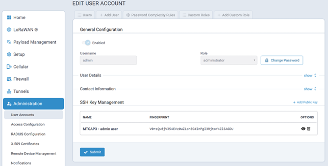
SSH Key Management
SSH public keys are managed in this section of the Users page.
- Engineer
- Monitor
- Custom role
Public keys that have been added to a user's account are listed in this section as well.
Add a New Public Key
To create a new public key associated with a user account click Add Public Key as shown here:
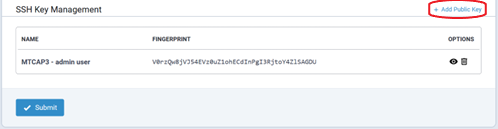
Paste the key into the Key field and assign a Title to the key:
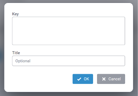
The system will not allow a public key to be added/created for a user if one has already been added.
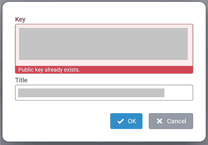
View a Public Key
To view a public key, click on the ![]() icon associated with the key to be viewed.
icon associated with the key to be viewed.
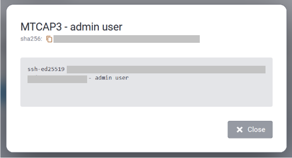
Delete a Public Key
To delete a public key, click on the ![]() icon associated with the key to be deleted.
icon associated with the key to be deleted.
Users Tab
A typical Users tab is illustrated here:
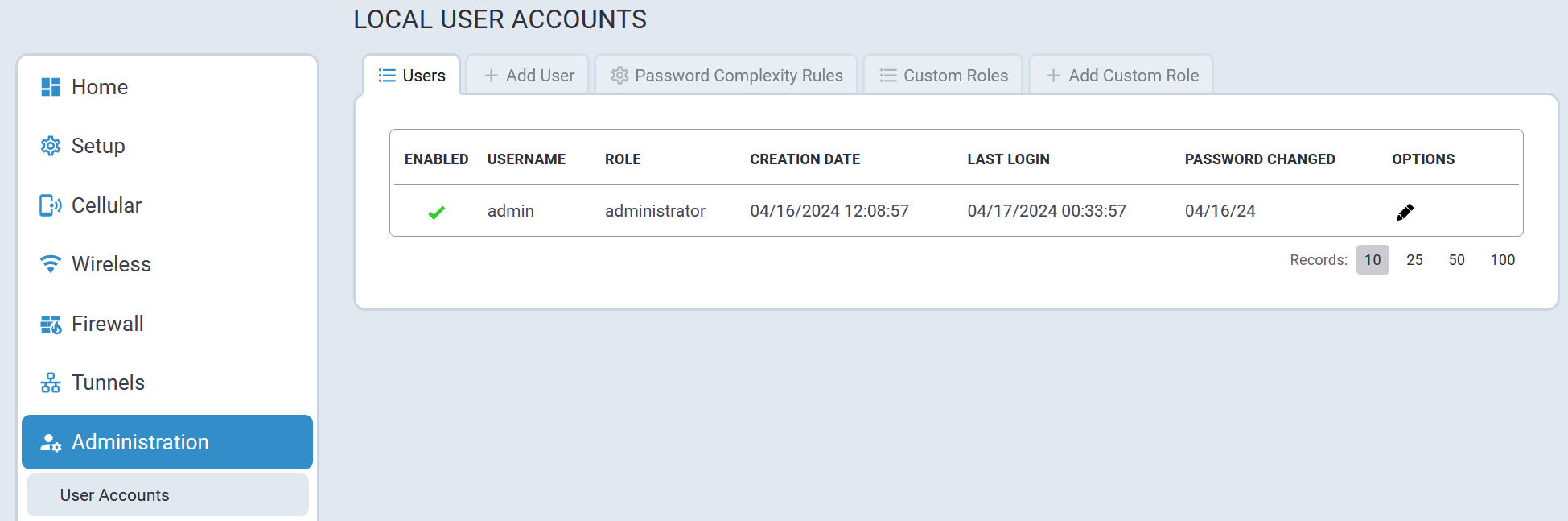
Add User Tab
When adding a user, a User Role must be assigned to that user. By default, the system supports three user roles:
- Administrator
- Engineer
- Monitor
A typical Add User screen is shown here:
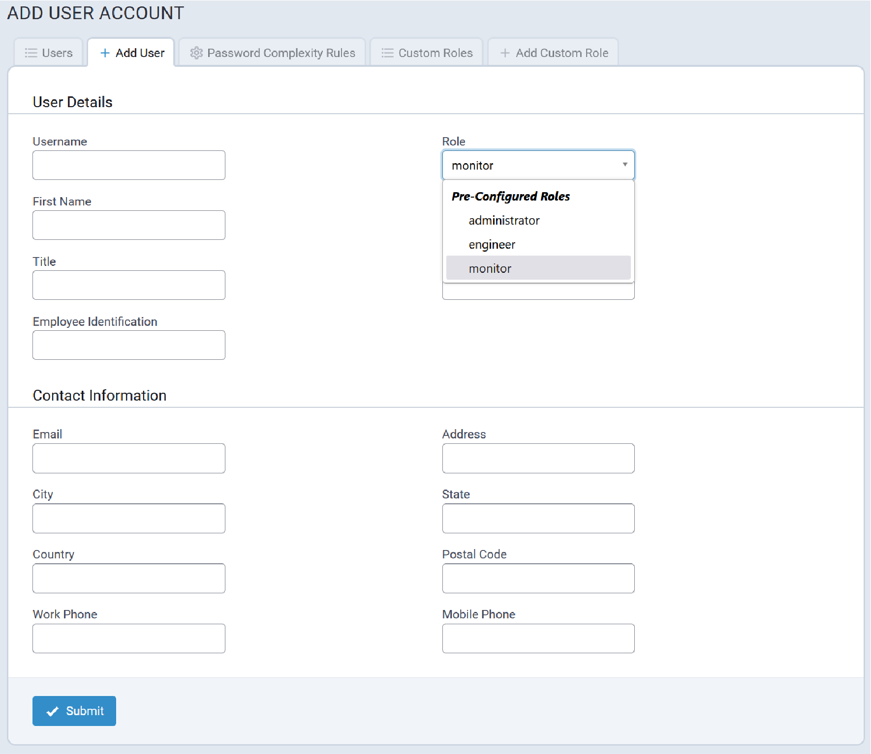
When Custom Roles have been added to the system, they will be listed as well, as illustrated here:
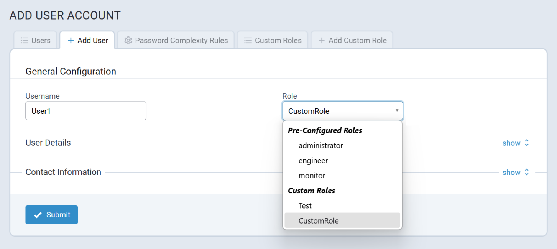
Password Complexity Rules Tab
Password complexity is managed through the facilities in Linux and PAM. There is a default complexity mode that is configurable. There is also the credit mode that is available in Linux distributions configurable to require a minimum credit score on a new password.
A typical Password Complexity Rules tab is illustrated here:
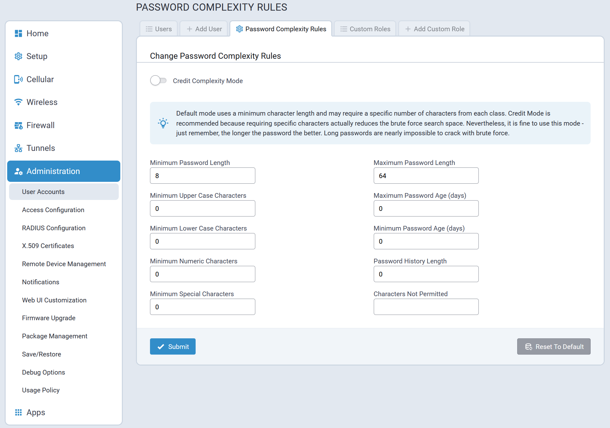
Custom Roles Tab
The Custom Roles tab lists all Custom User Roles that have been added to the system. For example:
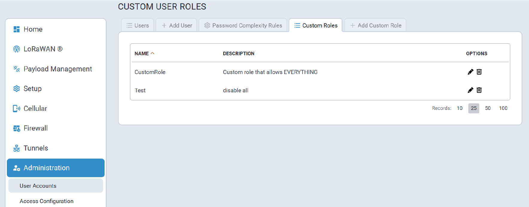
Add Custom Role
A typical Add Custom Role tab is illustrated here:
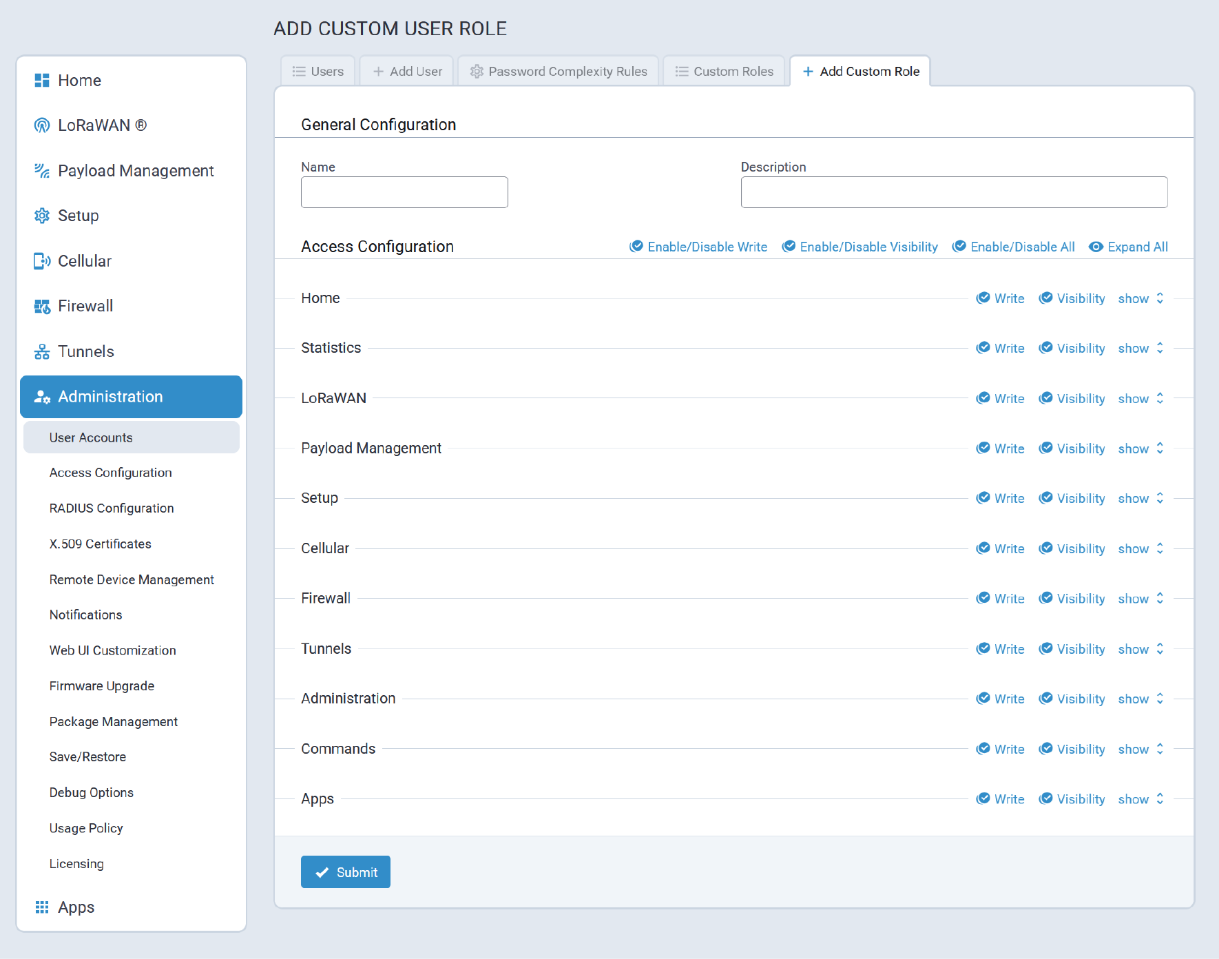
Sample custom User Role settings are illustrated here:
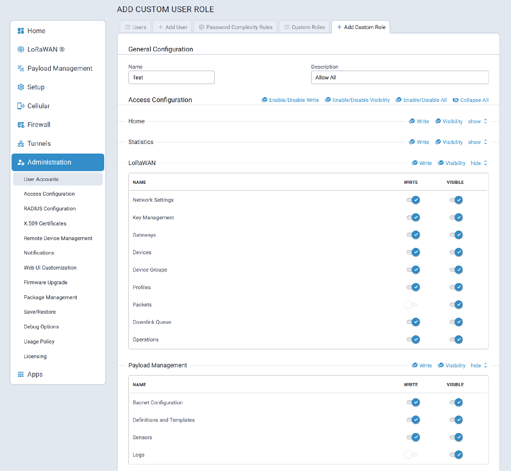
Access Configuration
Access Configuration settings allow users to configure a variety of services on the device such as:
- The Web Server for the mPower API used by the mPower Web UI
- Responsiveness to Pings to the device on the LAN and WAN interfaces
- The SNMP server
- The Modbus server
- Enabling and limited configuration of:
- DoS prevention
- Ping Limiting
- Brute Force Prevention to lock out user accounts that exceed the password failure limits
- SSH Authentication
- Reverse SSH Tunnel
A typical Access Configuration landing page is illustrated here:
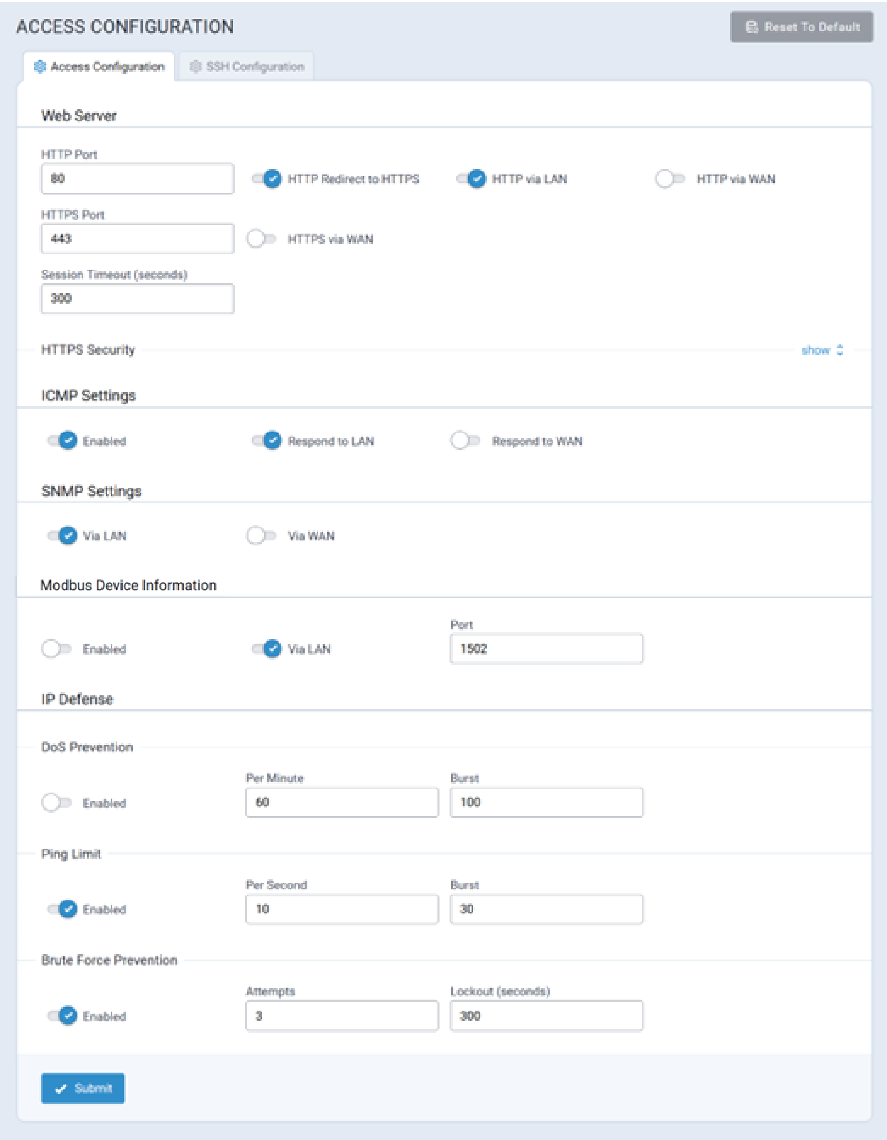
- Access Configuration
- SSH Configuration
The following sections provide detailed information about each parameter used to configure device services.
Access Configuration Tab
- Web Server information
- ICMP
- SNMP
- Modbus Device Information
- IP Defense
Web Server Configuration
The Conduit® AP 300 only allows secure access to its Web UI. The following parameters configure how HTTP requests are redirected to the Conduit® AP 300's secure HTTPS port.
| Parameter | Description |
|---|---|
| HTTP Port | The port on which the Conduit® AP 300 listens for HTTP requests to redirect. |
| HTTP Redirect to HTTPS | When enabled, users accessing the Conduit® AP 300 via HTTP are automatically redirected to the secure HTTPS port. |
| HTTP via LAN | When enabled, the Conduit® AP 300 listens for and redirects incoming HTTP requests from the LAN to HTTPS. |
| HTTP via WAN | When enabled, the Conduit® AP 300 listens for and redirects incoming HTTP requests from the WAN to HTTPS. |
| HTTPS Port | The port on which the Conduit® AP 300 listens for HTTPS requests. |
| HTTPS via WAN | When enabled, the Conduit® AP 300 listens for and responds to HTTPS requests from the WAN. This increases susceptibility to malicious activity. |
| Session Timeout (seconds) | Amount of time a user's session can remain dormant before automatically being logged out (minutes).Note: Changing this item requires the device to reboot. |
HTTPS Security
Configure the HTTPS security settings (like version and cipher suite). Click the Show link to the right under HTTPS Security. To enable the Web server to authenticate the client via the client’s public key certificate, check Client Authentication under the Authentication section.
| Parameter | Description |
|---|---|
| Authentication | |
| Client Authentication | Requires web browsers to have a valid client certificate that is signed by a Certifying Authority (CA) that the server can verify. Otherwise, user access to the UI is blocked. NOTE: You must first upload a CA certificate at Administration > X.509 CA Certificates. |
| TLS Settings | |
| TLSv1.3, TLSv1.2, and/or TLSv1.1 | Check the version of the TLS protocol to be used: TLSv1.3, TLSv1.2, and/or TLSv1.1 (Deprecated). Default: TLSv1.3 and TLSv1.2 |
| Cipher Suite Name | Check any preferred Cipher Suite from the following: TLS_AES_256_GCM_SHA384, TLS_CHACHA20_POLY1305_SHA256,TLS_AES_128_GCM_SHA256, ECDHE-RSA-AES256-GCM-SHA384, ECDHE-RSA-AES128-GCM-SHA256,TLS_AES_128_GCM_SHA256, and also including the following deprecated ciphers: ECDHE-RSA-AES256-GCM-SHA384, ECDHE-RSA-AES256-SHA, DHE-RSA-AES256-GCM-SHA384, AES256-SHA, ECDHE-RSA-AES128-GCM-SHA256, ECDHE-RSA-AES128-SHA, DHE-RSA-AES128-GCM-SHA256, DHE-RSA-AES128-SHA, and/or AES128-SHA. Default: All. (You can also set the priority order of the ciphers). |
ICMP
Internet Control Message Protocol (ICMP) is used by devices to send error messages such as that a requested service is not available or a host or device could not be reached. ICMP can also relay query messages.
| Parameter | Description |
|---|---|
| Enabled | Enables ICMP responses. |
| Respond to LAN | If checked, the device will respond to ICMP traffic from the LAN, such as ping requests. |
| Respond to WAN | If checked, the device will respond to ICMP traffic from the WAN, such as ping requests. This increases susceptibility to malicious activity. |
SNMP
The Conduit® AP 300 offers Simple Network Management Protocol (SNMP) which is used for collecting information from, and configuring network devices on an IP network.
| Parameter | Description |
|---|---|
| Via LAN | When enabled, the Conduit® AP 300 allows access to the SNMP server via the LAN. |
| Via WAN | When enabled, the Conduit® AP 300 allows access to the SNMP server via the WAN. |
Modbus Device Information
The Modbus feature allows the user to enable the Modbus query server. You can query this server over Modbus-TCP for status information.
| Parameter | Description |
|---|---|
| Enabled | Enables the Modbus Query Server. |
| Via LAN | When enabled, the Conduit® AP 300 can query the Modbus server via the LAN. |
| Port | Port number configured for Modbus. |
For Modbus query information, refer to the MTR Modbus Information page on our Developer Resources website (on .net) for details: http://www.multitech.net/developer/software/mtr-software/mtr-modbus-information/
IP Defense Settings
A set of rules that decreases susceptibility to malicious activity. If these settings are configured too strictly, they may interfere with non-malicious activity.
DoS Prevention
| Parameter | Description |
|---|---|
| Enabled | Enables DoS prevention (disabled by default). |
| Per Minute | Allowed number of new connections per minute until burst points are consumed. For example, if 60 new connections are received in a minute, decrement one burst point. If no more burst points, drop the packet. |
| Burst | Number of allowed burst for traffic spikes. A burst occurs when the Per Minute limit is reached. On a period where the Per Minute limit is not reached, one burst point is regained, up to the maximum. |
Ping Limit
| Parameter | Description |
|---|---|
| Enabled | Enables the Ping Limit feature (enabled by default). |
| Per Second | Allowed number of pings per second before burst points are consumed. Once burst points run out, ICMP packets will be dropped. |
| Burst | Number of burst points. On a period where the Per Second limit is not reached, one burst point is regained, up to this maximum. |
Brute Force Protection
| Parameter | Description |
|---|---|
| Enabled | Enables the Brute Force Prevention feature (enabled by default). |
| Attempts | The number of failed attempts allowed before the user's account is locked out. |
| Lockout Minutes | The number of minutes an account is locked out before a new login attempt will be accepted. |
Bootloader Protection
To see or set these features, go to Administration > Access Configuration > Bootloader Protection and click Show.
Bootloader Shell
This feature enables shell access to the bootloader. It is disabled by default. If the Conduit® AP 300 is reset to factory defaults, Bootloader Shell Access is disabled.
- Under Bootloader Shell Access, click Enable.
- Confirm the change.
- If not making other changes, click Submit.
When enabled, the status shows as Enabled and a Disable button appears. Click Disable to turn off Shell Access and confirm the change. The change is applied immediately.
Bootloader Password
This feature enables password authentication to access the Conduit® AP 300 bootloader. Bootloader password is set directly to the bootloader. The password is not removed or disabled when resetting to factory defaults. Once you setup a bootloader password, it stays in the bootloader until you disable it.
It is disabled by default.
| Parameter | Description |
|---|---|
| Enabled | Enables the Bootloader Password feature to the right of Authentication Status (enabled by default). |
| Password | Enter password to access the Conduit® AP 300 bootloader. |
| Confirm | Enter the password again to confirm. |
Debug Console
This feature allows the customer to run Silent Mode which turns off the output to the Debug Console. The console output is enabled by default (i.e. Silent Mode is disabled).
When Silent Mode is enabled, Debug Console is turned off. (NOTE: During boot, the device does not output any information after the notice that the Linux Kernel is being decompressed including no login prompt, etc.)
| Parameter | Description |
|---|---|
| Enable | Enables Silent Mode which turns off output to the Debug Console (disabled by default meaning Debug Console output is on). |
After making all desired changes, click Submit, then click Save and Apply. (Changes to specific sections may require reboot.)
SSH Configuration Tab
The SSH Configuration tab allows users to configure SSH services on the device such as:
- SSH Settings
- Authentication
- Brute Force Prevention
- SSH Security
- Reverse SSH Tunnel
A typical SSH Configuration page is illustrated here:
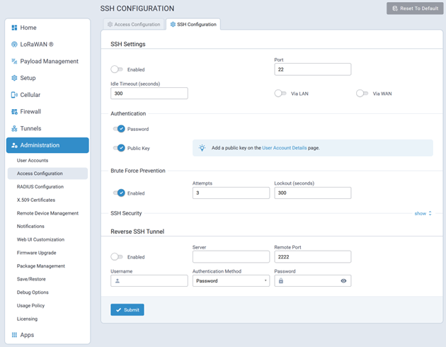
SSH Settings
Typical SSH configuration settings are illustrated here:
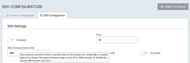
Idle Timeout (seconds)
Idle Timeout is the length of time, in seconds, that an SSH session will remain idle or inactive before the system automatically closes it.
Valid values, in seconds, for Idle Timeout are:
- 60
- 3600
The default value for Idle Timeout is 300 seconds.
SSH Authentication
SSH Authentication is where the following authentication settings are controlled:
- Password authentication
- Public Key authentication
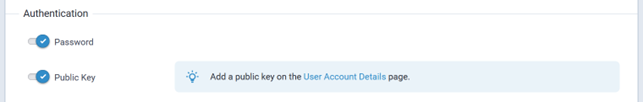
SSH Brute Force Prevention
SSH Brute Force Prevention protects the system from unauthorized access attempts and prevents attackers from repeatedly trying different passwords to gain SSH access.
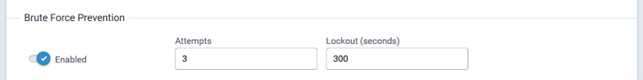
- Enabled: true|false
- Attempts: 1 – 99
- Lockout (seconds): 60 — 3600
- Brute Force Prevention: enabled
- Attempts: 3
- Lockout (seconds): 300 (i.e., 5 minutes)
RADIUS Configuration
The RADIUS protocol supports authentication, user session accounting, and authorization of users to the device.
This authentication, accounting, and authorization is independent of the local users created on the device. The user can enable Authentication, Accounting, or both options.
RADIUS user details:
- Access to device if role is one of those in the provided list (Administrator, Engineer, or Monitor).
- All RADIUS users do not have SSH access to the device.
- RADIUS creates a temporary session instead of a local account like local users.
- RADIUS uses shared key encryption.
- Local users shall take priority over RADIUS user (if a RADIUS user has the same username as a local user, the RADIUS user cannot log in even if the local user is disabled).
- RADIUS user with Administrator role can view and modify all local users (but cannot delete a local Administrator if it is the only local admin user on the device).
- RADIUS users with Engineer and Monitor role cannot view or modify user details. They do not have access to the User Accounts page.
- RADIUS users cannot change their own password in the Web UI.
A typical Radius Configuration page is illustrated here:
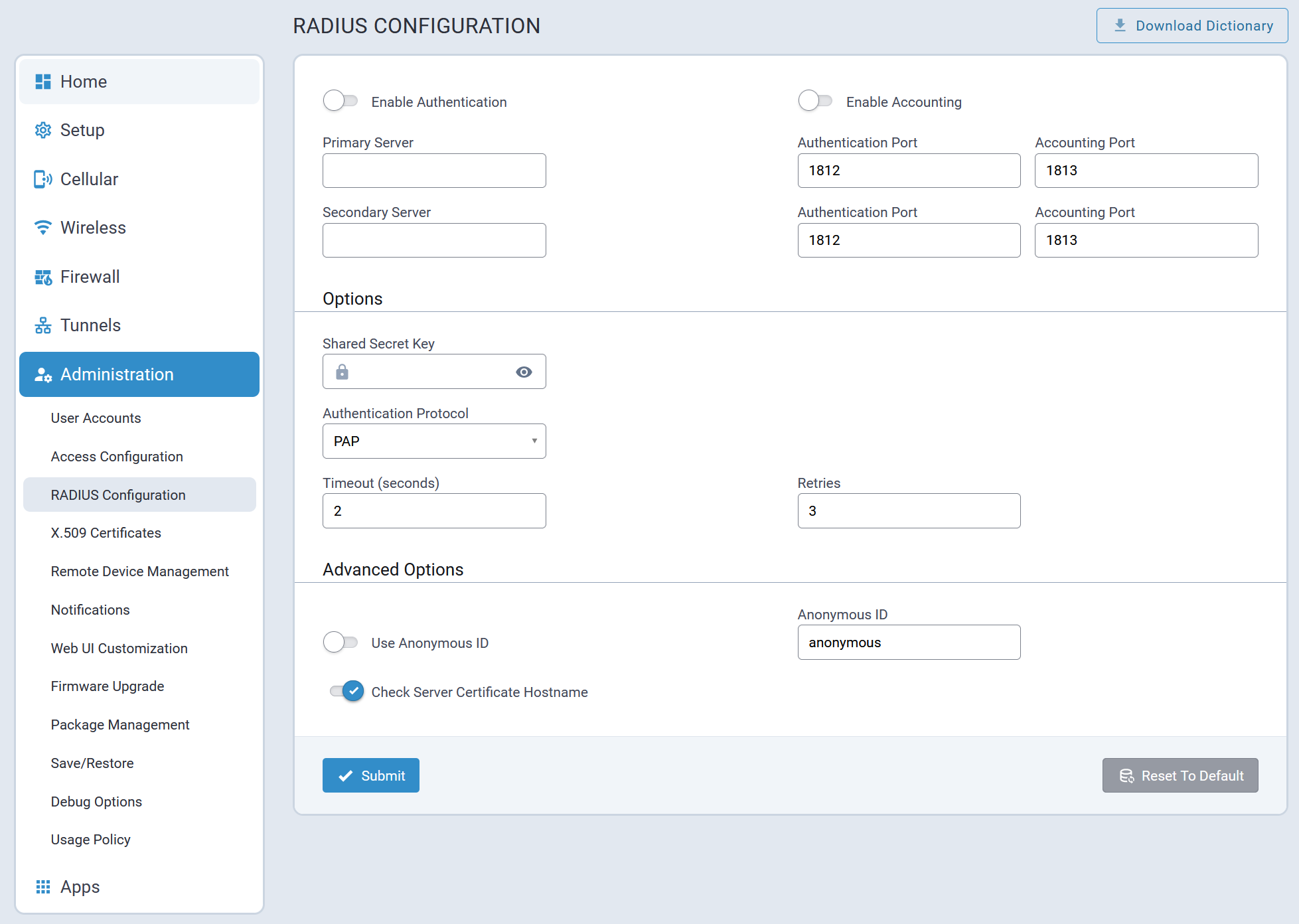
X.509 Certificates
A typical X.509 Certificates configuration page is illustrated here:
Web Certificate
The system supports generating and uploading a new Web Certificate in .pem format.
A typical Web Certificate tab is illustrated here:
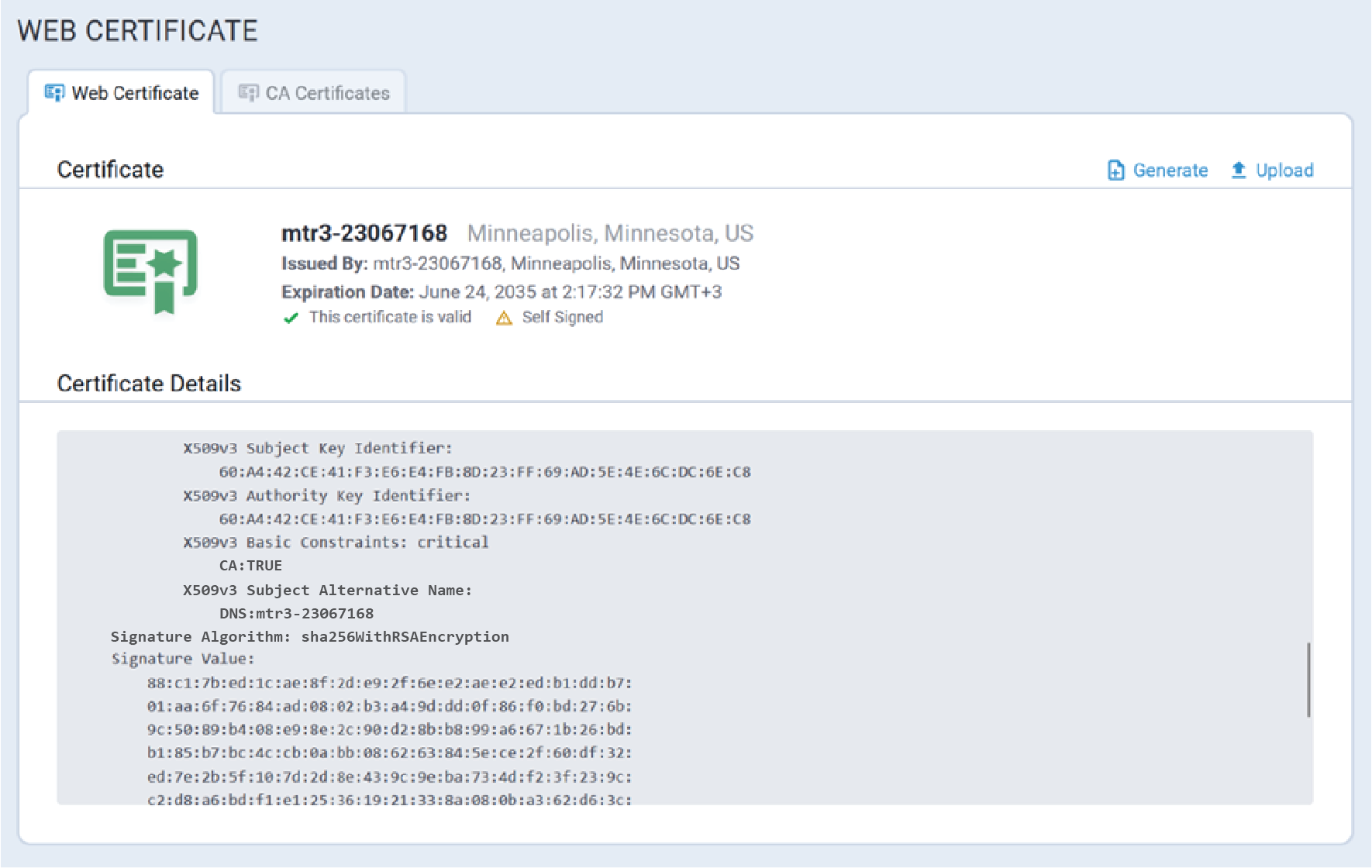
Generate Web Certificate
To generate a new web certificate, click on  on the Web Certificate page.
A typical Generate Web Certificate configuration pop-up dialog is illustrated here:
Web Certificate Configuration Parameters
| Parameter | Valid Values | Description |
|---|---|---|
| Common Name | ||
| Subject Alternative Name | The following types may be added to the self-signed
certificate:
|
Subject Alternative Name (SAN) is an extension to the X.509
specification that allows users to specify additional host names for
a single SSL certificate. SAN is used in modern X.509 certificates
to:
The system generates a self-signed certificate using
the device hostname as a SAN value.
|
| Locality/City | ||
| Days | ||
| Organization | ||
| Country (2 letter code) | ||
| Email Address | ||
| State/Province |
CA Certificates Tab
The system supports importing X.509 CA Certificates. Imported certificates must be in .pem format.
A typical CA Certificates tab is illustrated here:
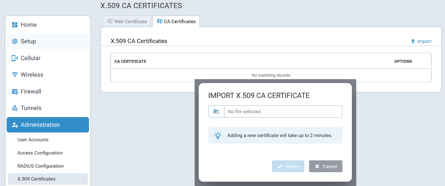
Remote Device Management
The following Remote Device Management operations are supported:
- Check-in based on a specified interval, and repeated at a particular time and day(s) of the week
- Upload device configuration to the remote server
- Commands execution:
- Configuration upgrade
- Firmware upgrade
- Device Logs Upload
- Reboot
A typical Remote Device Management tab is illustrated here:
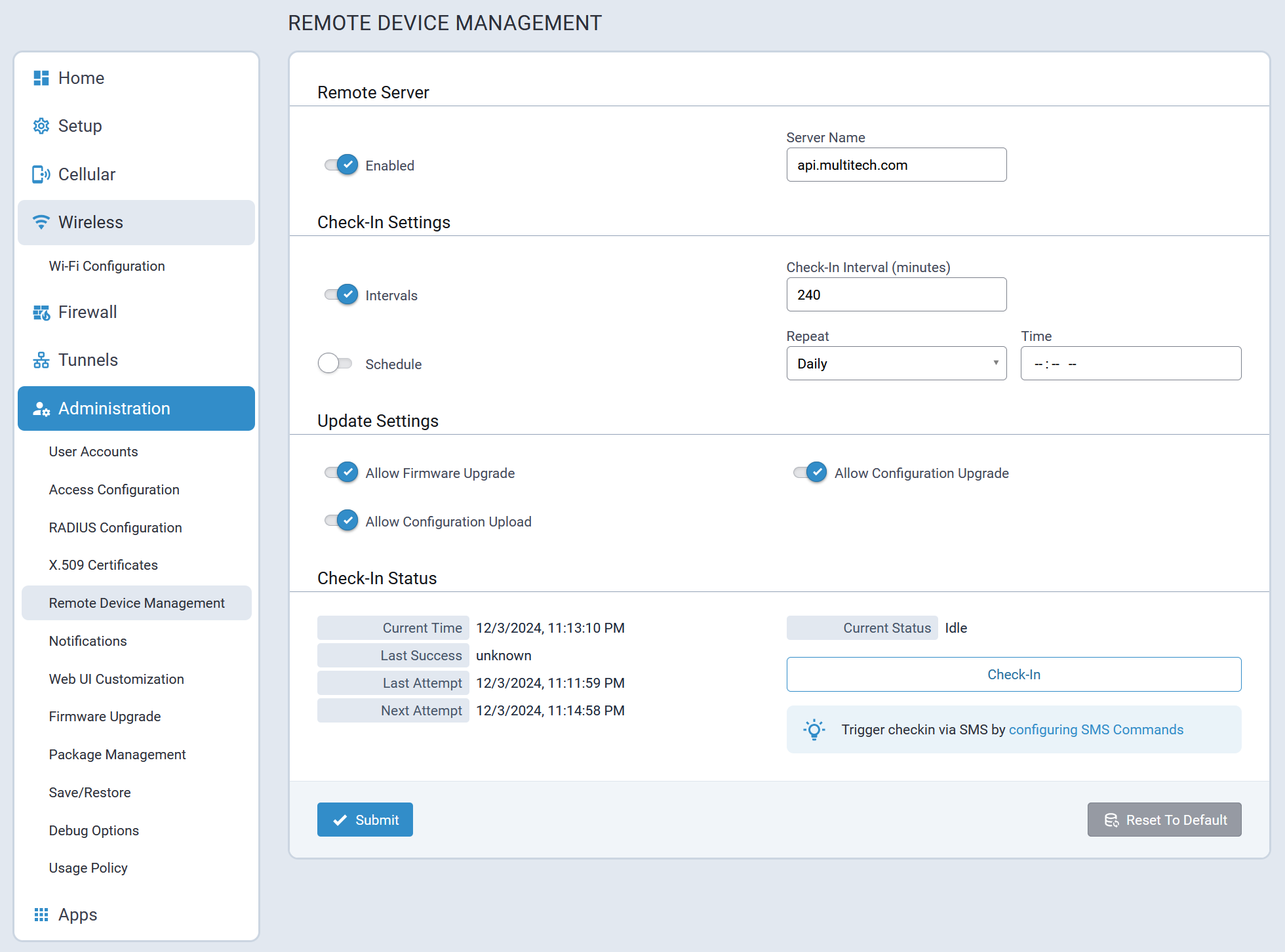
Notifications
The Notification tab includes settings for users to manage the following:
- Notifications Configuration
- Notifications Sent
The device can send alerts via:
- email
To send alerts via email, the SMTP server must be enabled.
- SMS
To send alerts via SMS, SMS must be enabled.
- SNMP
To send SNMP traps, SNMP trap feature must be enabled and SNMP trap destinations must be configured.
Configuration Tab
A typical Configuration tab for notifications is illustrated here:
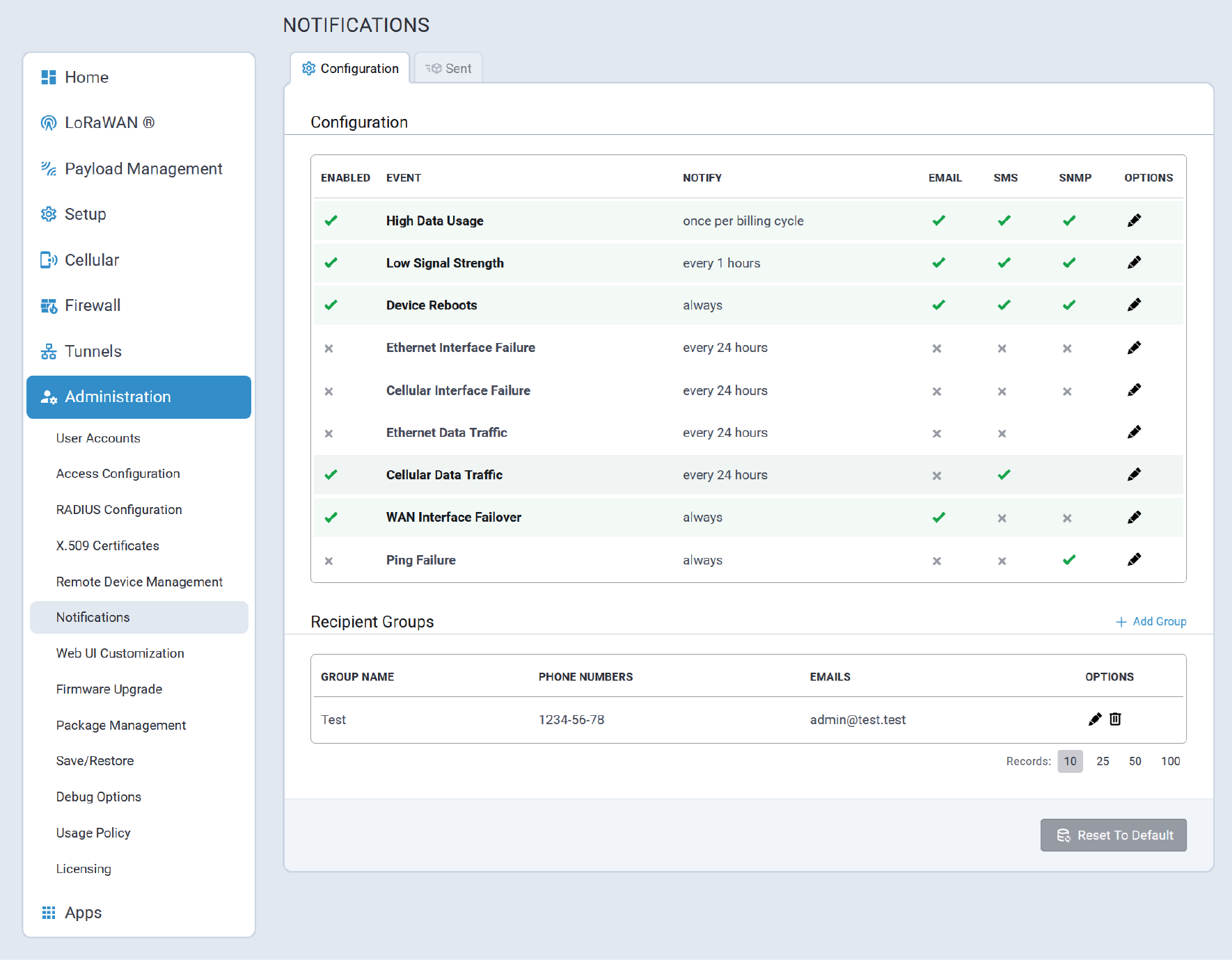
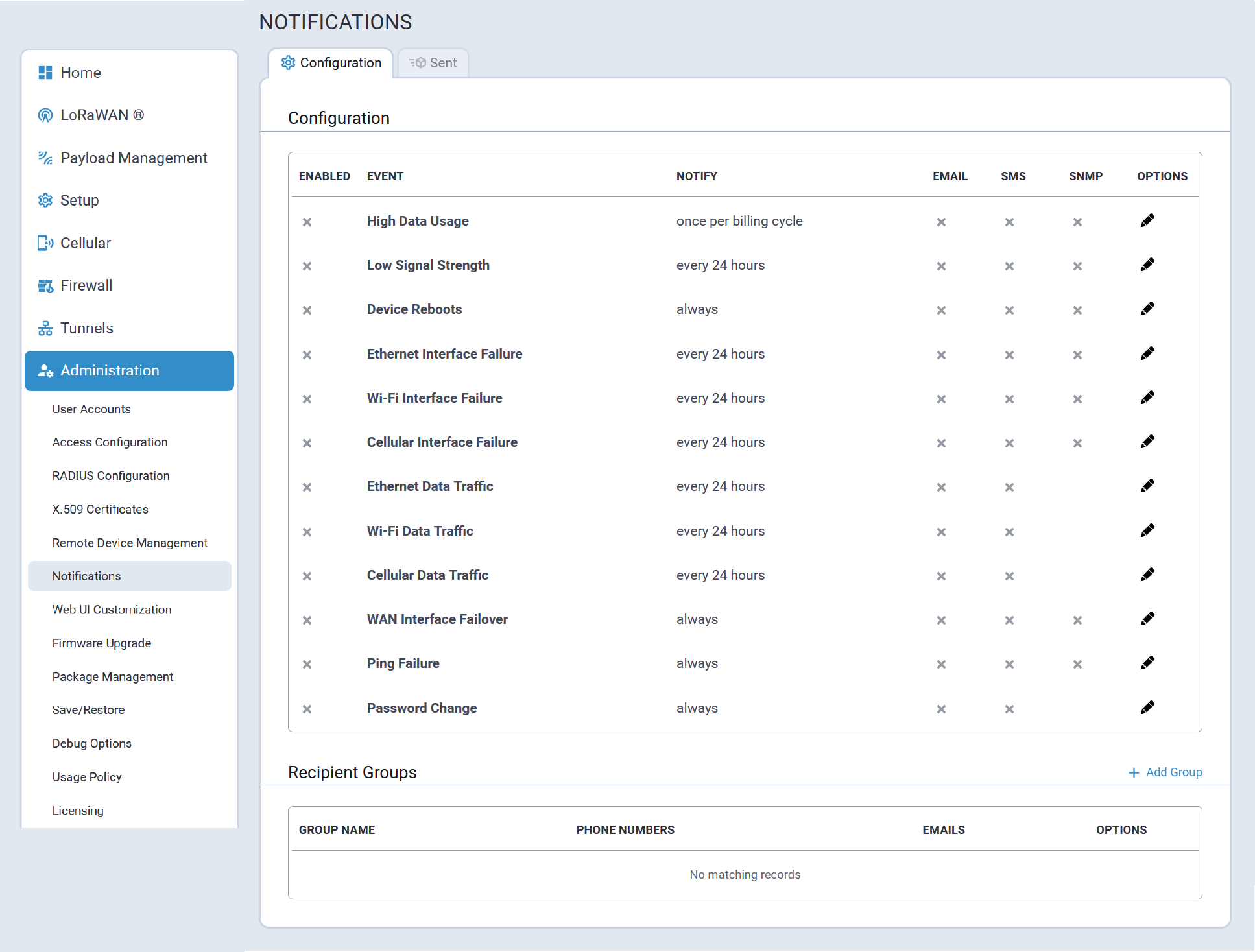
- High Data Usage - the system sends an alert on the cellular data traffic limit,
as defined by the user, is exceeded for a specified interval. This is only
available for cellular devices.

- Low Signal Strength - the system sends an alert when the cellular signal
strength is less than a set value for a specified interval. This is only
available for cellular devices.

- Device Reboots - the system sends an alert when the device reboots.
- Ethernet Interface Failure - the system sends an alert when the Ethernet eth0
interface is not available during a specified interval.
- Wi-Fi Interface Failure - the system sends an alert when the wlan0 interface
(Wi-Fi as WAN) is not available during a specified interval. This is only
available for devices that have Wi-Fi.
- Cellular Interface Failure - the system sends an alert when the cellular
interface is not available during a specified interval. This is only available
for cellular devices.
- Ethernet Data Traffic - the system sends the data traffic statistics for the
Ethernet interface. SNMP traps cannot be sent for this notification.
- Wi-Fi Data Traffic - the system sends the data traffic statistics for the Wi-Fi
as WAN interface. This is only available for devices that have Wi-Fi and SNMP
traps cannot be sent for this notification.
- Cellular Data Traffic - the system sends the data traffic statistics for the
cellular interface. This is only available for cellular devices and SNMP traps
cannot be sent for this notification.
- WAN Interface Failover - the system sends an alert when a WAN failover occurs.
- Ping Failure - the system sends an alert when an attempt to ping fails.
- Password Change - the system sends an alert when a user’s
password changes. SNMP traps cannot be sent for this notification.
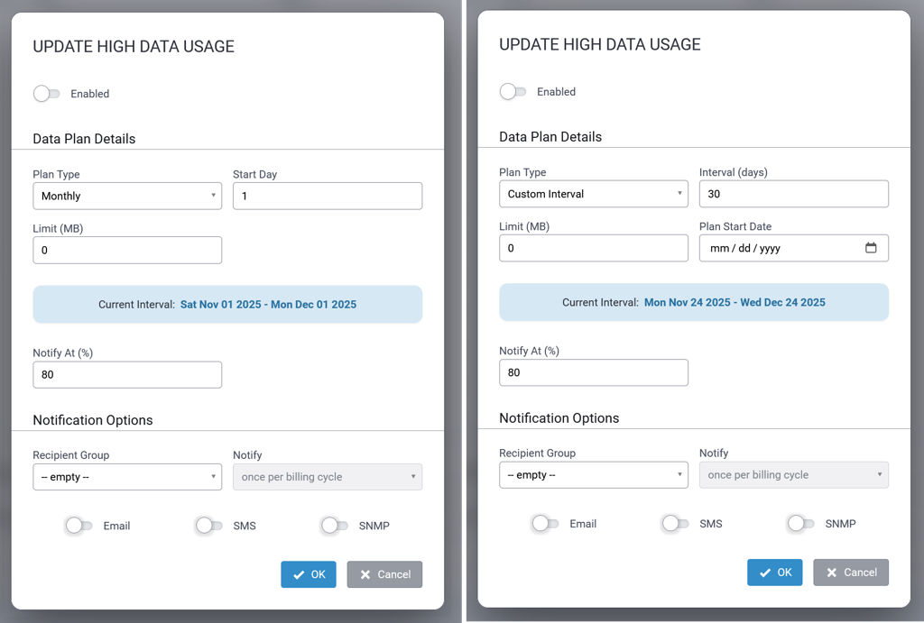
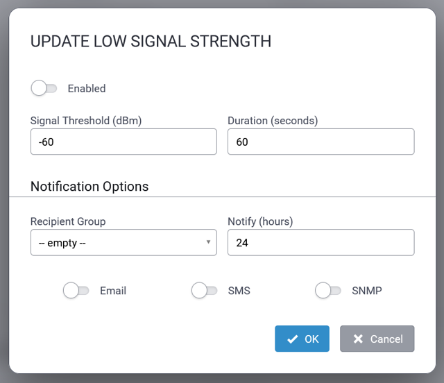
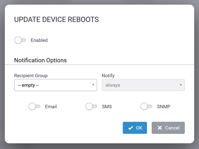
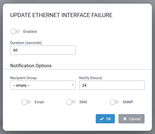
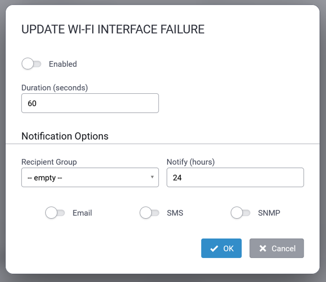
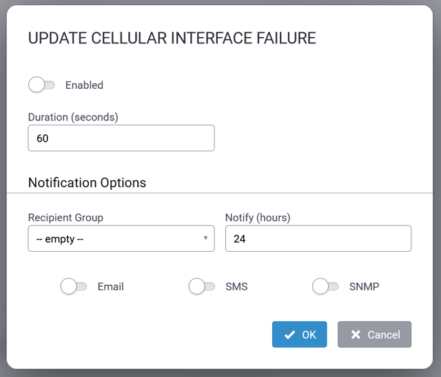
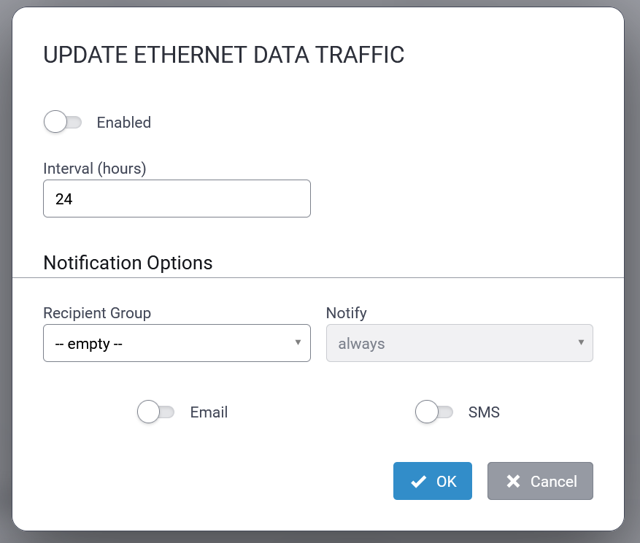
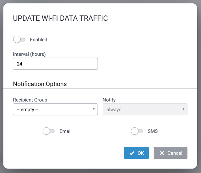
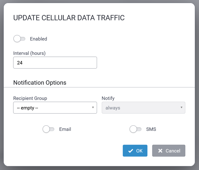
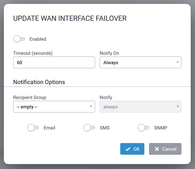
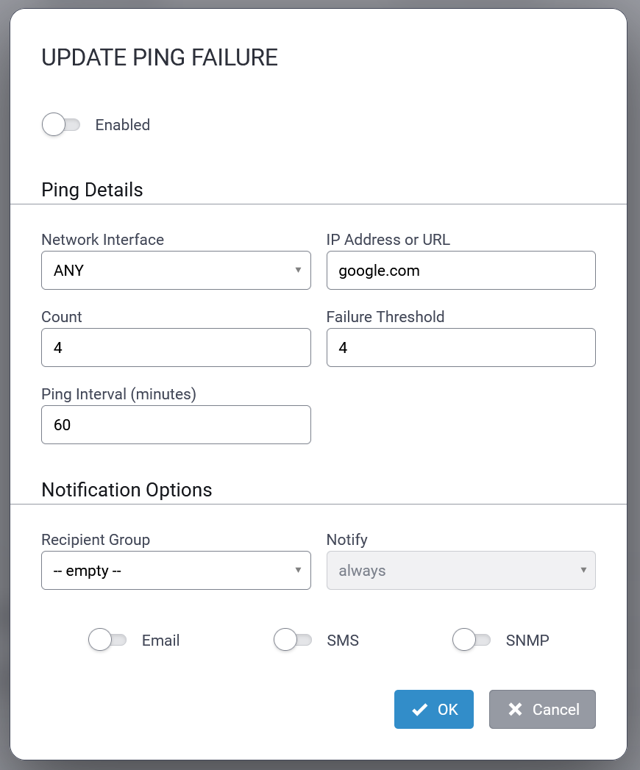
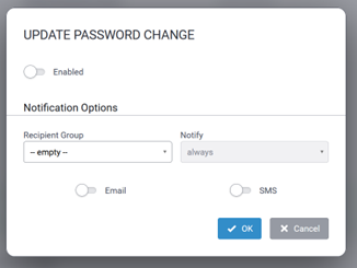
To add a new Recipient Group, click on + Add Group and configure the following information for the group:
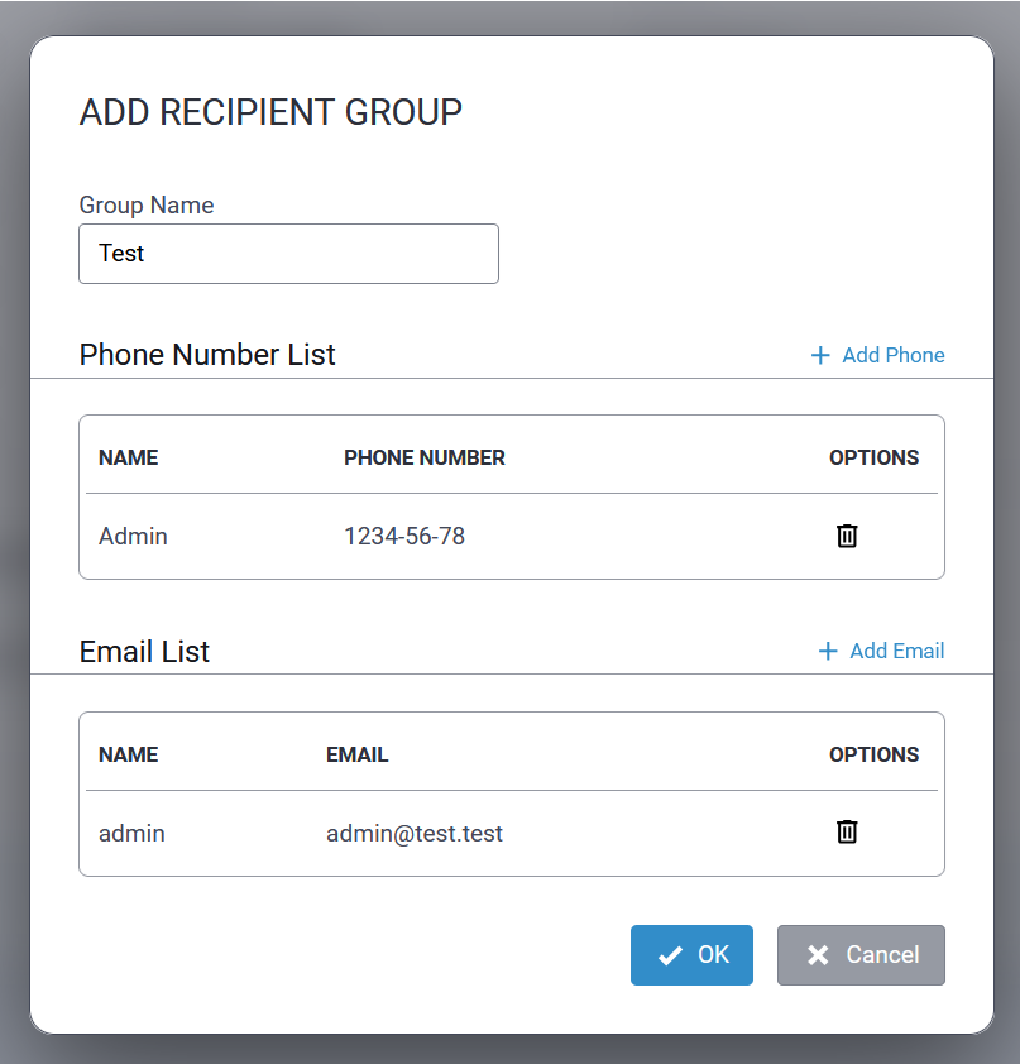
To edit an existing Recipient Group, click the ![]() associated with the group to be edited. Add or
delete contact information as required.
associated with the group to be edited. Add or
delete contact information as required.
Sent Tab
A typical Sent tab for notifications is illustrated here:
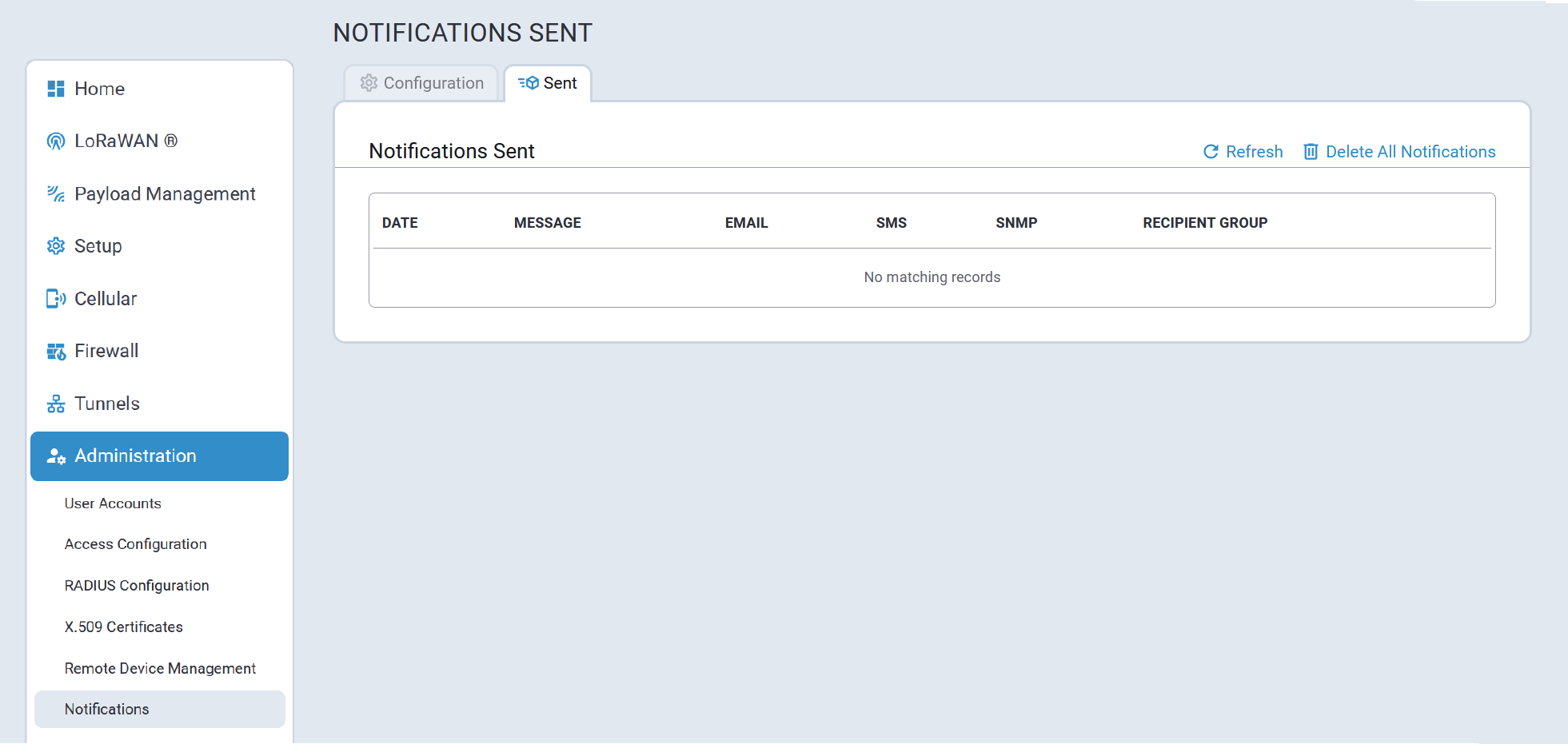
Web UI Customization
Users can configure the following on the Web UI Customization tab:
- Footer Customization allows the user to add custom organization details to the footer.
- Dashboard Customization allows the user to upload a new image and specify Device Name and Custom ID that will be shown on the Dashboard page.
- UI Customization allows the user to modify the color schema of the buttons, and upload a custom logo and favicon.
A typical Web UI Customization tab is illustrated here:
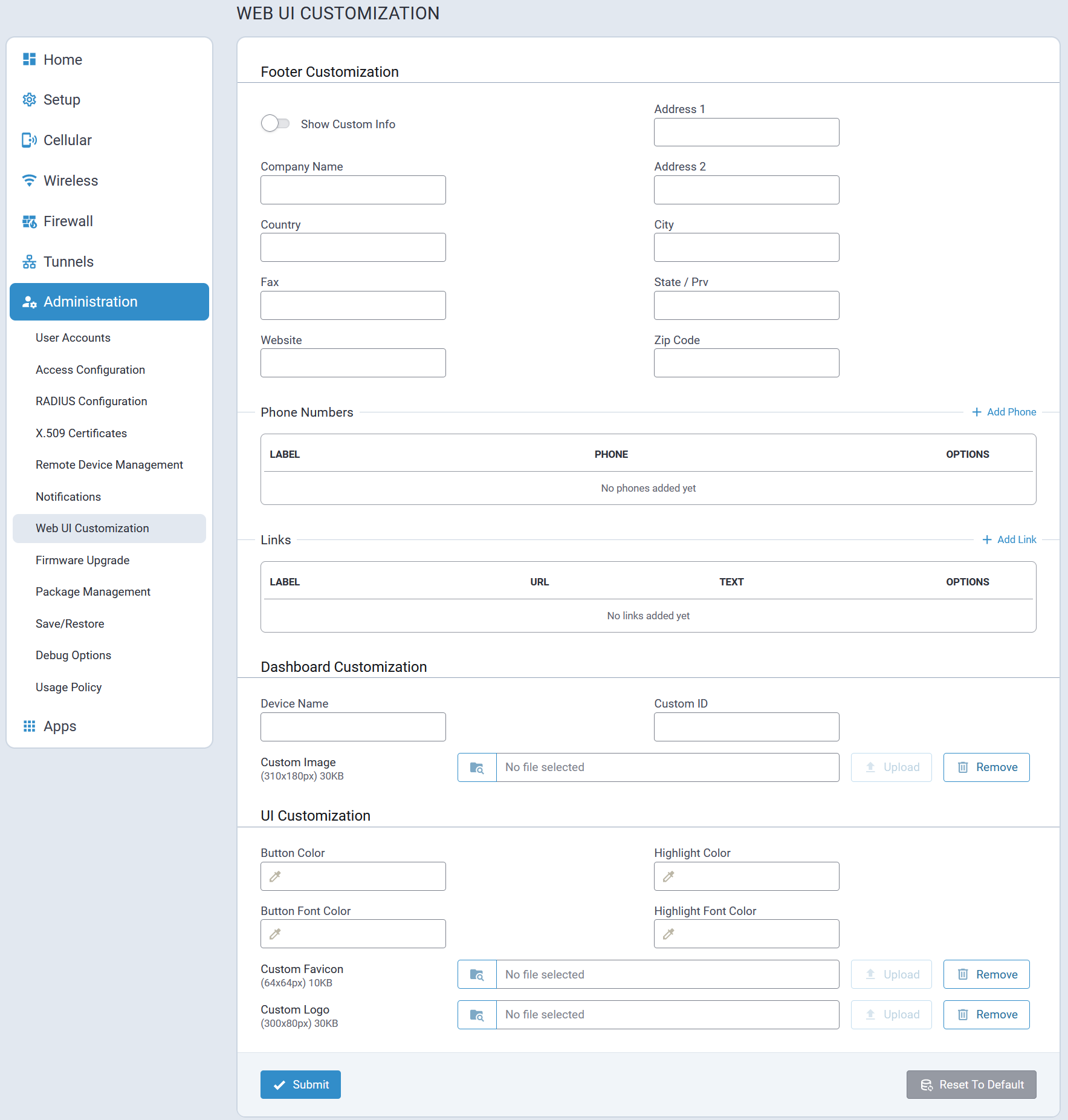
Firmware Upgrade
Firmware from MultiTech is signed by MultiTech’s private key and the signatures on the artifacts in the firmware must verify successfully for the firmware to be applied to the device flash.
Migration from mPower 6.x/DeviceHQ to mPower 7.x/MultiTech Cloud Device Manager - Starting in December 2025, MultiTech will roll out self-service device migration through MultiTech Cloud Device Manager (MTCDM). This option empowers you to handle your own device migrations with minimal intervention and provides a single portal to manage and upgrade your devices to the latest mPower firmware.
Because firmware upgrades are considered critical operations, they are protected from reboot until the upgrade completes. If the process runs longer than one hour, the system notifies users, logs a potential hang, and performs a controlled reboot.
A typical Firmware Upgrade screen is illustrated here:
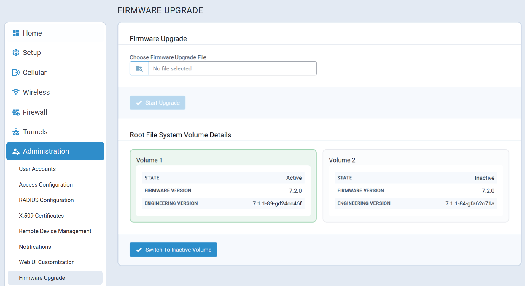
System Fallback
To improve system reliability and ensure system recovery, the Conduit® AP 300 employs a dual volume architecture.
Following a fallback, once the system successfully reboots the following message is displayed on the Firmware Upgrade screen to alert the user:
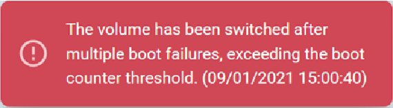
Package Management
The Package Management feature supports importing and installing packages from the MultiTech online mLinux feeds.
A typical Package Management tab is illustrated here:
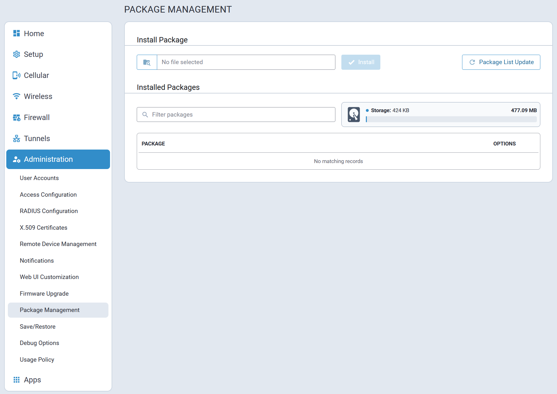
Save/Restore
Save/Restore supports restoring from an uploaded configuration file, saving the current configuration to a file, and resetting the device back to user-defined settings or factory defaults. You can configure the RESET button to restore a device to user-defined settings or factory defaults, to reboot only or to disable this function when the device reboots.
Before using these settings and features, you should clearly understand their behaviors and effects. A typical Save/Restore page is illustrated here:
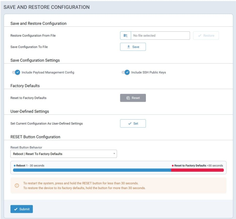
Save and Restore Configuration
To access the Save/Restore page from the navigation bar, go to Administration > Save/Restore > Save and Restore Configuration.
To restore a configuration from a previously saved file:
- Next to the Restore Configuration From File field, click Browse.
- Navigate to the location where the configuration file is stored and select it.
- Click Restore. The device reboots.
To save your current configuration to a file:
- Next to the Save Configuration To File, click Save.
- Navigate to the location where you wish to save the file and select it.
Factory Defaults
When you reset your device to factory defaults, the following actions occur:
- Your device restarts
- User-defined settings configuration is deleted (if set)
- All settings modified by the user are removed/returned to factory defaults
- All custom applications are deleted
- All Node-RED applications are deleted
- All installed packages are deleted
- Customer images, favicons, and logos are deleted
- CA certificates are deleted and new certificates are generated
- Your web server's SSL certificate is deleted and a new certificate is generated
- SSH certificates are removed and new certificates are generated
To reset the device's configuration to the factory defaults:
- Click Reset next to Reset Device to Factory Default Configuration.
- A message appears prompting you to confirm you want to restore to factory defaults.
- Click OK.
User-Defined Settings
You can set a current device configuration as user-defined settings. When you reset your device to user-defined settings, the following actions occur:
- Your device restarts, then it restores custom apps if they are present in the configuration, and it reboots the system again
- All settings modified by the user (not saved in the user-defined settings configuration) are removed/returned to user-defined settings
- var/persistent is not erased
- Installed packages are not included in user-defined settings configurations but are not deleted (when you reset to user-defined settings configuration, they are not restored this way)
By default, user-defined settings are not set until you configure them. You can then restore the device to your user-defined settings from the Save and Restore Configuration page or using the RESET button on the device, if configured to reset to user-defined settings.
To set the current configuration as user-defined settings, next to Set Current Configuration As User-Defined Settings:
- Click Set.
- A message appears prompting you to confirm you want to save the current configuration as user-defined settings.
- Click OK. This enables the Reset and Clear buttons.
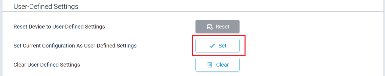
To reset the device's configuration to user-defined settings, next to Reset Device to User-Defined Settings:
- Click Reset.
- A message appears prompting you to confirm you want to reset to a set of user-defined settings.
- Click OK. The device reboots.
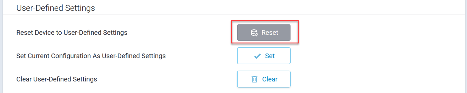 To clear user-defined settings, next to Clear User-Defined
Settings:
To clear user-defined settings, next to Clear User-Defined
Settings:
- Click Clear.
- A message appears asking if you want to clear user-defined settings.
- Click OK.
![]()
The system does not allow you to set the user-defined settings if there are pending changes and the Save and Apply button is red. A warning message appears asking you to first save these changes.
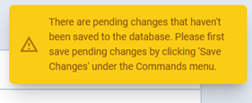
RESET Button Configuration
The following options are available from the RESET Button Behavior drop-down list:
- Reboot | Reset To Factory Defaults (default)
- Reboot | Reset to User Defined Settings | Reset To Factory Defaults
- Reboot | Reset to User Defined Settings
- Reboot Only
- Disabled
To reset to factory defaults:
- Select Reboot | Reset to Factory Defaults from the Reset Button Behavior drop-down list. This option is the default selection.
- Click Submit.
- Click Save and Apply to save your changes. No restart required.
The RESET button will perform a soft reset if pressed and held for up to 10 seconds. To reset the device to factory defaults, press and hold the RESET button for more than 30 seconds.
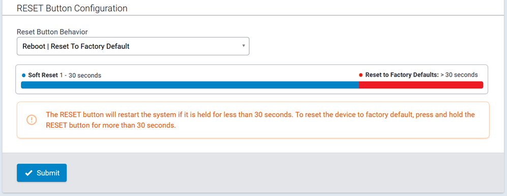
To reset both factory defaults and user-defined settings:
- Select Reboot | Reset to User Defined Settings | Reset To Factory Defaults from the Reset Button Behavior drop-down list.
- Click Submit.
- Click Save and Apply to save your changes. No restart required.
The RESET button will perform a soft reset if pressed and held for up to 10 seconds. To reset the device to the user-defined settings configuration, press and hold the RESET button for 11-30 seconds.
Note: If the user-defined settings configuration is not set, the device will perform a soft reset when pressed and held for 11-30 seconds. To reset the device to factory defaults, press and hold the RESET button for more than 30 seconds.
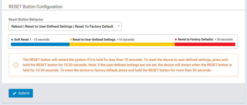
To reset to user-defined settings:
- Select Reboot | Reset to User-Defined Settings from the Reset Button Behavior drop-down list.
- Click Submit.
- Click Save and Apply to save your changes. No restart required.
The RESET button will perform a soft reset if pressed and held for up to 10 seconds. To reset the device to the user-defined settings configuration, press and hold the RESET button for 11-30 seconds. The RESET button will not allow you to restore the device to factory defaults.
Note: If the user-defined settings configuration is not set, the device will perform a soft reset when pressed and held for 11-30 seconds.
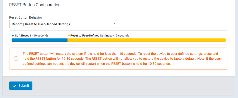
To reboot only:
- Select Reboot Only from the Reset Button Behavior drop-down list.
- Click Submit.
- Click Save and Apply to save your changes. No restart required.
The RESET button will always restart the system and will not allow you to restore the device to factory defaults or user-defined settings configuration.
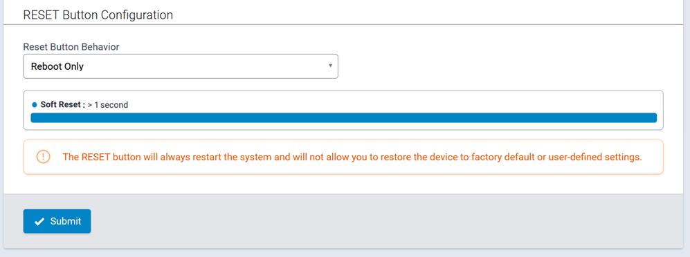
To disable the RESET button:
- Select Disabled from the Reset Button Behavior drop-down list.
- Click Submit.
- Click Save and Apply to save your changes. No restart required.
The RESET button will be disabled. The system will not allow you to restart or restore the device to factory defaults or user-defined settings via the RESET button.
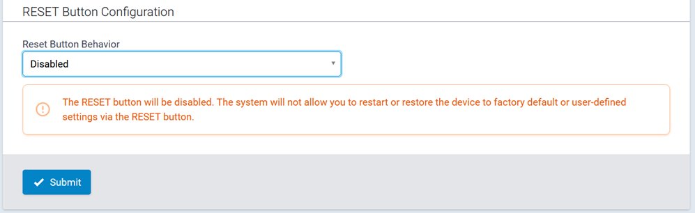
Note: Disabling factory default settings means there is no mechanism to restore the device to commissioning mode. Do not lose track of your login credentials or you will lose access to the device.
Warning and Confirmation Messages
Selecting either Reboot | Reset to User Defined Settings | Reset To Factory Defaults or Reboot | Reset to User Defined Settings from the Reset Button Behavior drop-down list when the user-defined settings configuration is not set results in the following message:
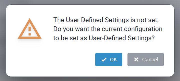
Click Cancel to exit the message or to set the user-defined settings configuration. This triggers the following message:
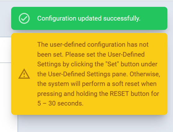
Click OK to set the current configuration as your User-Defined Settings. The system then applies the Reset Button Behavior configuration.

Setting the current configuration as user-defined settings when the RESET button is not configured to reset to a user-defined settings triggers a warning message. The message reminds you to configure the RESET button in the Reset Button Configuration section if you want to be able to reset to user-defined settings via pressing the button:
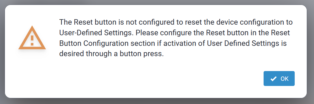
Click OK to close the message. The system continues setting up the current configuration for the user-defined settings. The system does not automatically apply the Reset Button Behavior configuration; instead, adjust this option and submit the changes directly, if needed.
Debug Options
The Debug Options tab contains a miscellaneous set of features and options for debugging and rebooting the device:
- When enabled, the Auto Reboot Timer feature reboots per the configured timeout. Options
include:
- Daily: Reboots the device at a specified time each day. If the variable interval is set to 0, the reboot occurs at the fixed scheduled time. To implement a randomized reboot window, configure a variable interval between 15 and 120 minutes.
- Timer: Reboots the device at a recurring hourly interval.
- Auto reboots are blocked during firmware upgrades, cell radio firmware upgrades, and custom application installations until all critical tasks finish. If any operation runs longer than an hour, the system notifies users, logs a potential hang, and then performs a controlled reboot.
- When enabled and configured, the Remote Syslog feature streams the syslog output to the remote server.
- Logging is a global setting to increase or decrease the device logging level. The system
handles log files during reboot as follows:
- Before each reboot, the device saves all log files to persistent storage and inserts the marker message “@@@ SAVED TO PERSISTENT STORAGE [qu30Ac] @@@" into each file.
- The six-character ID in brackets (for example, [qu30Ac]) is unique to each reboot event, allowing you to identify and trace all log messages associated with a specific reboot session.
- The Data Traffic Statistics feature controls the periodicity and data threshold when statistics are saved to persistent storage.
- The Ping feature pings or connects via TCP to the target remote host.
- The Continuous Ping feature pings the target remote host continuously.
A typical Debug Options tab is illustrated here:
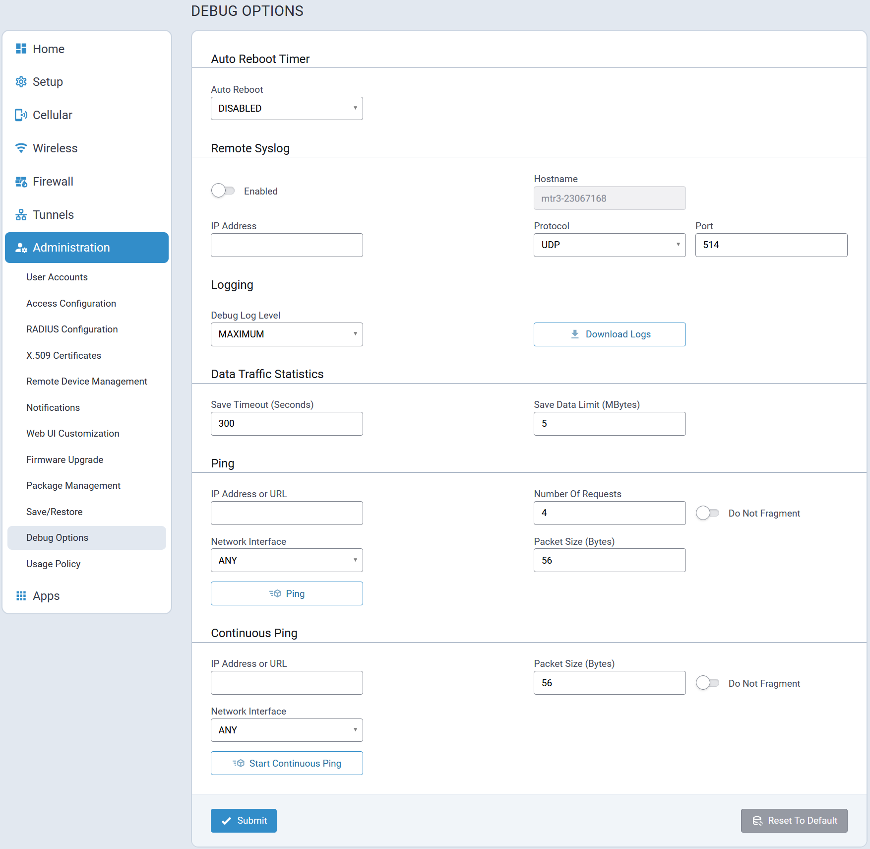
Usage Policy
A typical Usage Policy tab is illustrated here:
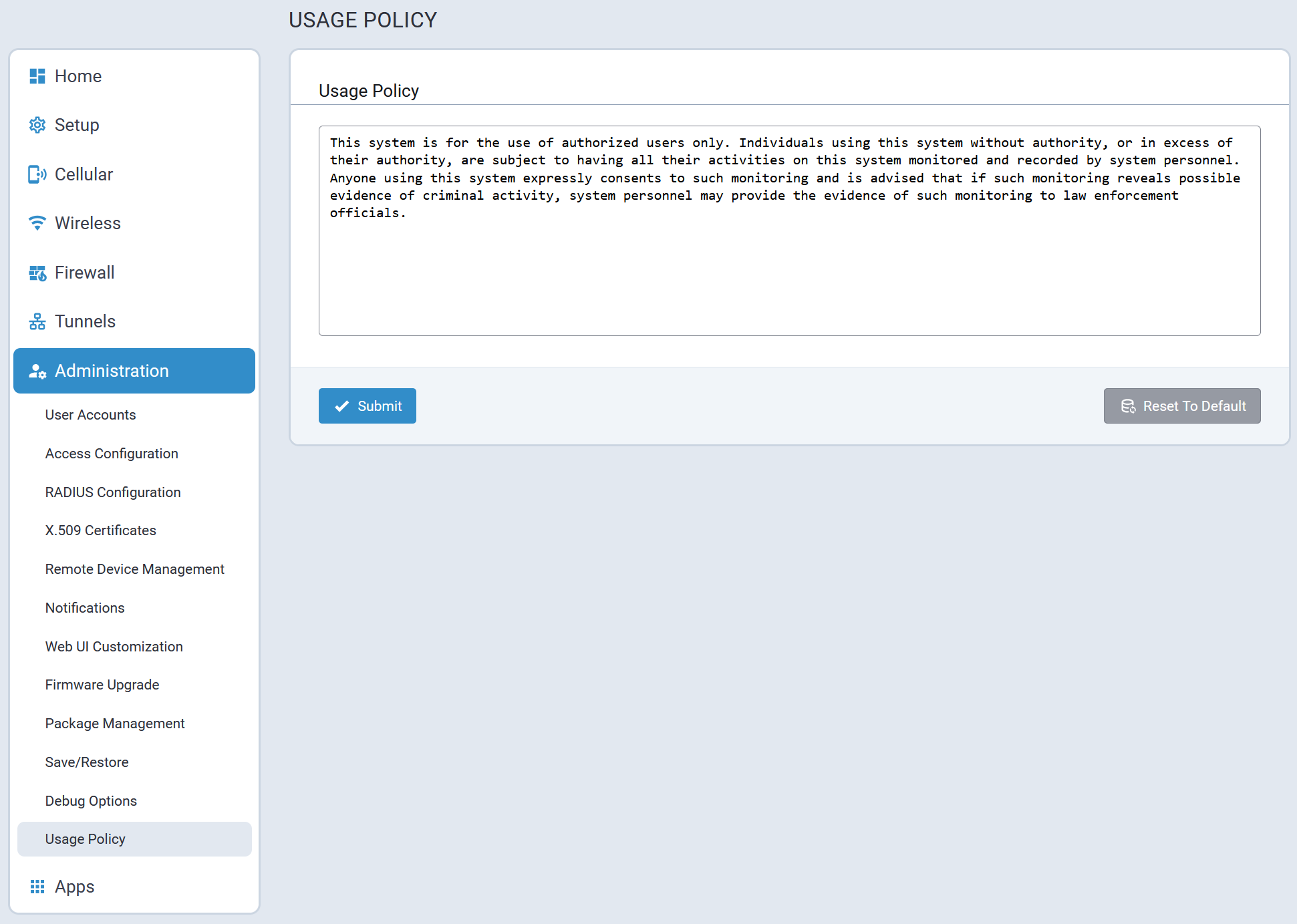
Licensing
This page shows licenses on this device. Some licenses are factory installed. If you add a licensed feature after receiving the device and have a license file to add:
- Go to Administration > License.
- Click Add New in the upper right corner.
- Add the License Key and Password.
- Click OK.
Apps Menu
Custom Apps
The system allows installing custom applications and uploading configuration files for the installed custom apps.
Because custom application installations are classified as critical operations, they are protected from reboot until installation finishes. If the task exceeds one hour, the system notifies users, logs a potential hang, and executes a controlled reboot.
A typical Custom Apps page is illustrated here:
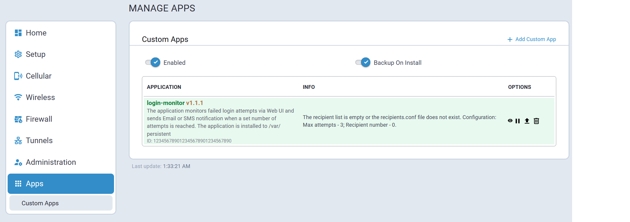
| Parameter | Description |
|---|---|
| Enabled | When ENABLED:
|
| Backup on Install | When ENABLED (default setting) the currently running custom application is backed up in case a new version of the application is being downloaded and installed. If the install fails, the backup is reinstalled. Disable this option only if there is not enough space to backup custom apps. |
 button associated with the application to be stopped. For
additional information, refer to Installed Applications.
button associated with the application to be stopped. For
additional information, refer to Installed Applications.Installed Applications
A list of custom applications that have been installed on the Conduit® AP 300 is displayed on the Custom Apps page. A typical list is shown here:
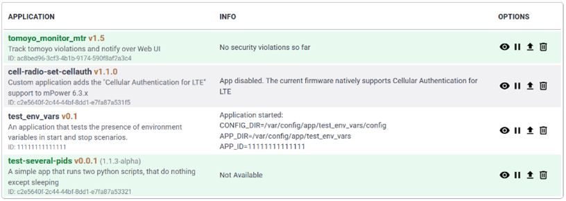
Information about available application options is listed here:
| Icon | Function |
|---|---|
 |
View application details |
|
Halt application |
 |
TBD |
 |
Delete the application |
View Application Details
option is selected:- Application Name
- Application ID
- Application Version
- Extra Version [optional]
- Installation Location
- Persistent Storage
- /var/config/app
- SD Card
- Application Status
- Application Description
- Version Notes
- Application Info; Not displayed if info is empty or "not available".
- Process IDs (PIDs)
- Process ID
- Running
- Process Name
- CMD
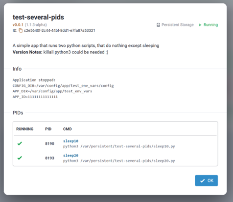
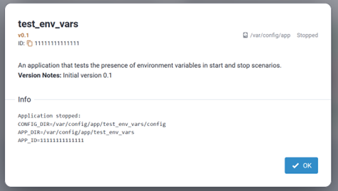
Application Status
The list of supported application statuses are provided below:
| Status | Description |
|---|---|
| STARTED | The application is highlighted with green and there is a stop action in the Options column. |
| RUNNING | The application is highlighted with green and there is a stop action in the Options column. |
| STOPPED | The application is not highlighted and there is a start action in the Options column. |
| FAILED | The application is highlighted with red and the actual status is shown next to the app version. |
| INSTALL FAILED | The application is highlighted with red and the actual status is shown next to the app version. |
| START FAILED | The application is highlighted with red and the actual status is shown next to the app version. |
Extra Version Support
In addition to a custom application's version, which is stored in manifest.json, some applications may have an optional extra version which is managed by the custom application itself. The extra version is stored in the [App Directory]/version_extra file.
If the [App Directory]/version_extra file exists and is not empty, the extra version is displayed next to the application's current version.
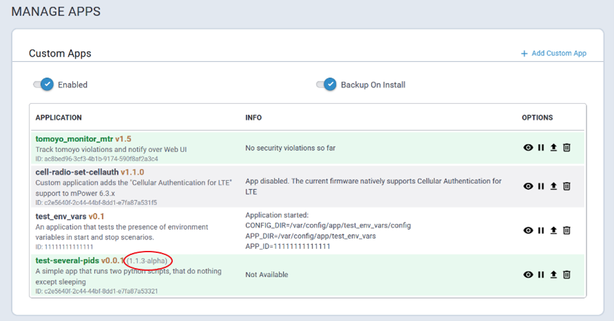
Install a Custom App
Perform the following procedure to install a custom application:
- Go to the Custom Apps page, select Add Custom App.
- Specify an App ID and an choose an application file in the pop up. The App ID must be a hexadecimal value with a maximum length of 32 characters.

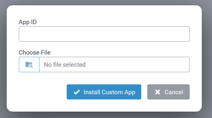
When adding a custom app, the following information applies:
- The application name must be unique. The system does not allow installing two different apps with the same name. The system retrieves the App Name value from the manifest.json.
- The installed application has a corresponding unique App ID. When installing an app, the system verifies if the app with the same name is already installed. If this is true, the system does not allow specifying a different App ID.
- If a user installs a new version of the application that is already installed, the user has to specify the App ID of the installed application. If the user specifies a different App ID, the application installation will fail and corresponding error message will be displayed.
- When installing an app, the system does not allow specifying an App ID that is already used by another application.
- The application's name
- Description
- Installed version
- App ID
- Current status
- Application information
Installation Location
The location where the system installs a custom application is defined in the manifest.json file. The application can be installed to /var/config/app, /var/persistent, or to the SD card.
To install the application to /var/persistent, the manifest.json file shall have the “PersistentStorage” field set to true. If it is absent or set to false, then the app will be installed to the /var/config/app directory.
Example:
{
  "AppName": "Application Name" ,
  "AppVersion": "Application Version" ,
  "AppDescription": "Description to be displayed for the custom app",
  "AppVersionNotes":"Any applicable notes for this version of the app.",
  "PersistentStorage": true
}
The system allows uploading one or more configuration files for the installed custom application.
To upload a new configuration file, select the Upload App Configuration icon in the Actions column.
The files will be uploaded to the /[AppName]/config directory.
- If the /[AppName]/config directory does not exist, the system will create a “config” directory in the application directory.
- You have to specify files with a correct file name that the application supposes to use. If the application uses general.conf, and you upload general_v1.conf and general_v3.conf, all these files will be present in the /config directory, and it depends on the app how to use them. If the file name of the file you upload corresponds to a file from the /config directory, new file will replace the existing one.
Send Notification Utility
Send Notification is a command-line utility providing a simple method to send notifications via SMS and e-mail.
The path to the utility is: /usr/bin/send-notification
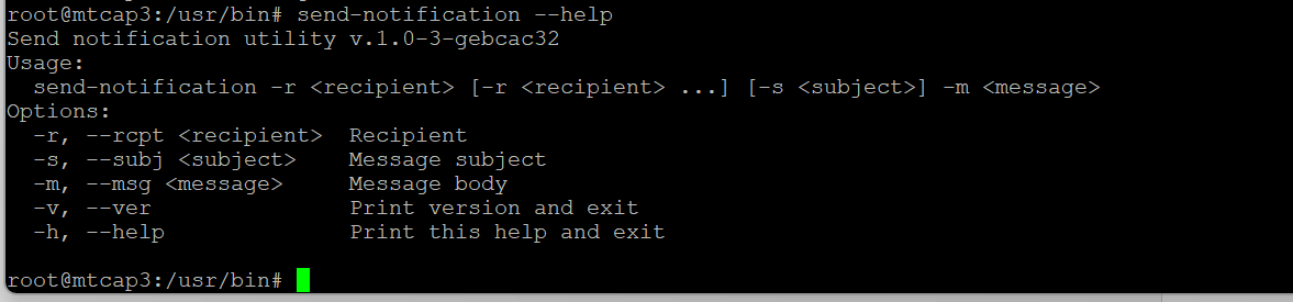
Send Notifications supports sending notifications to one or more recipients allowing one notification to be sent to multiple recipients simultaneously.