MultiTech LoRaWAN Wireless Sensors
Models:
- RBS3010NA01BN00 / RBS3010EU01BN00 / RBS3010AU01BN00 LoRaWAN Door/Window Sensor (US915 / EU868 / AU915)
- RBS3010NA03BN00 / RBS3010EU03BN00 / RBS3010AU03BN00 LoRaWAN Dry Contact Sensor (US915 / EU868 / AU915)
- RBS3010NA05BN00 / RBS3010EU05BN00 / RBS3010AU05BN00 LoRaWAN External Probe Temperature Sensor (US915 / EU868 / AU915)
- RBS3010NA08BN00 / RBS3010EU08BN00 / RBS3010AU08BN00 LoRaWAN Accelerometer-based Movement Sensor (US915 / EU868 / AU915)
- RBS3010NA09BN00 /RBS3010EU09BN00 / RBS3010AU09BN00 LoRaWAN Tilt Sensor (US915 / EU868 / AU915)
- RBS3010NA0ABN00 / RBS3010EU0ABN00 / RBS3010AU0ABN00 LoRaWAN Water Leak Sensor with Probe (US915 / EU868 / AU915)
- RBS3010NA0ABN08 / RBS3010EU0ABN08 / RBS3010AU0ABN08 LoRaWAN Water Leak Sensor with 1M Water Rope (US915 / EU868 / AU915)
- RBS3010NA0ABN0B / RBS3010EU0ABN0B / RBS3010AU0ABN0B LoRaWAN Water Leak Sensor with 5M Water Rope (US915 / EU868 / AU915)
- RBS3010NA0ABN09 / RBS3010EU0ABN09 / RBS3010AU0ABN09 LoRaWAN Water Leak Sensor with 10M Water Rope (US915 / EU868 / AU915)
- RBS3010NA0EBN00 / RBS3010EU0EBN00 / RBS3010AU0EBN00 LoRaWAN Integrated Temperature and Humidity Sensor (US915 / EU868 / AU915)
- RBS3010NA19BN00 / RBS3010EU19BN00 / RBS3010AU19BN00 LoRaWAN Internal Temperature Sensor (US915 / EU868 / AU915)
- RBS3010NA22BN00 / RBS3010EU22BN00 /RBS3010AU22BN00 LoRaWAN Temp, Humidity and Water Leak Probe Sensor (US915 / EU868 / AU915)
- RBS3010NA22BN08 / RBS3010EU22BN08 / RBS3010AU22BN08 LoRaWAN Temp, Humidity and 1M Water Rope Sensor (US915 / EU868 / AU915)
- RBS304-1-US LoRaWAN Push Button Sensor (US915)
- RBS306-420MA-US LoRaWAN Armored 4-20mA Current Loop Sensor (US915)
- RBS306-ABM-US LoRaWAN Armored Acceleration-based Movement Sensor (US915)
- RBS306-ATH-EXT-US LoRaWAN Armored External Probe Air Temperature/Humidity Sensor (US915)
- RBS306-CON-US LoRaWAN Armored Dry Contact Sensor (US915)
- RBS306-MBHR-US LoRaWAN Armored Maxbotix HR Series Ultrasonic Sensor Bridge (US915)
- RBS306-TEMP-EXT-US LoRaWAN Armored External-Probe Temperature Sensor (US915)
- RBS306-TEMP-TC-US LoRaWAN Armored Thermocouple Temperature Sensor (US915)
- RBS306-TILT-HP-US LoRaWAN Armored High Precision Tilt Sensor (US915)
- RBS306-US10M-US LoRaWAN Armored Ultrasonic Level Sensor 10 Meter (US915)
- RBS306-VM30-US LoRaWAN Armored Voltage Sensor (US915)
- RBS306-VSHB-11-US LoRaWAN Vibration Sensor, single axis single probe (US915)
- RBS306-WR1M-US LoRaWAN Armored Water Rope Sensor 1 Meter (US915)
- RBS306-WR10M-US LoRaWAN Armored Water Rope Sensor 10 Meter (US915)
- RBS3010NA27BN00 / RBS3010EU27BN00 / RBS3010AU27BN00 LoRaWAN Door/Window Sensor with Air Temperature and Humidity (US915 / EU868 / AU915)
- RBS301+NA28BN00 / RBS301+EU28BN00 / RBS301+AU28BN00 Pulse Counter (US915 / EU868 / AU915)
Document Part Number: S000826 Rev. 1.4
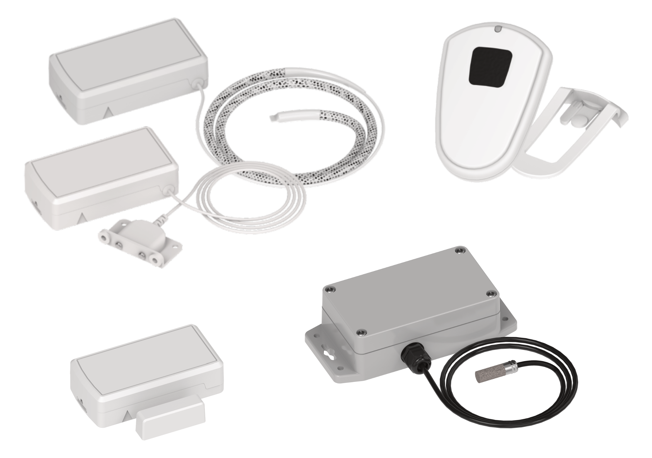
Overview
This section provides an overview of the LoRaWAN Wireless Sensors by category with part numbers, rating, and region information.
LoRaWAN Door/Window Sensor
The LoRaWAN Door/Window Sensor uses a Hall effect sensor to register open/close events for doors and windows by detecting the presence of a magnet. The device sends both Door Opened and Door Closed events.
| Part Number | Sensor Name | Rating | Sensor Family | Region |
|---|---|---|---|---|
| RBS3010NA01BN00 | LoRaWAN Door/Window Sensor | Indoor | 301 | US915 |
| RBS3010EU01BN00 | LoRaWAN Door/Window Sensor | Indoor | 301 | EU868 |
| RBS3010AU01BN00 | LoRaWAN Door/Window Sensor | Indoor | 301 | AU915 |
LoRaWAN Dry Contact Sensor
The LoRaWAN Dry Contact Sensors detect a shorted connection between two wires. The device sends both Contact Open or Contact Shorted events.
| Part Number | Sensor Name | Rating | Sensor Family | Region |
|---|---|---|---|---|
| RBS3010NA03BN00 | LoRaWAN Dry Contact Sensor | Indoor | 301 | US915 |
| RBS3010EU03BN00 | LoRaWAN Dry Contact Sensor | Indoor | 301 | EU868 |
| RBS3010AU03BN00 | LoRaWAN Dry Contact Sensor | Indoor | 301 | AU915 |
| RBS306-CON-US | LoRaWAN Armored Dry Contact Sensor | Outdoor/Industrial | 306 | US915 |
LoRaWAN External Temperature Sensor
The LoRaWAN External Temperature Sensors measure temperature in degrees Celsius using an external thermistor probe with a precision of 1 degree. Available alerts include upper and lower threshold crossing, incremental change, and periodic interval.
| Part Number | Sensor Name | Rating | Sensor Family | Region |
|---|---|---|---|---|
| RBS3010NA05BN00 | LoRaWAN External Probe Temperature Sensor | Indoor | 301 | US915 |
| RBS3010EU05BN00 | LoRaWAN External Probe Temperature Sensor | Indoor | 301 | EU868 |
| RBS3010AU05BN00 | LoRaWAN External Probe Temperature Sensor | Indoor | 301 | AU915 |
| RBS306-TEMP-EXT-US | LoRaWAN Armored External-Probe Temperature Sensor | Outdoor/Industrial | 306 | US915 |
LoRaWAN Acceleration-based Movement Sensor
The LoRaWAN Acceleration-based Movement Sensors use an accelerometer to detect any movement of the device that exceeds a configurable threshold. Available alerts include both movement started and movement stopped.
| Part Number | Sensor Name | Rating | Sensor Family | Region |
|---|---|---|---|---|
| RBS3010NA08BN00 | LoRaWAN Accelerometer-based Movement Sensor | Indoor | 301 | US915 |
| RBS3010EU08BN00 | LoRaWAN Accelerometer-based Movement Sensor | Indoor | 301 | EU868 |
| RBS3010AU08BN00 | LoRaWAN Acceleration-based Movement Sensor | Indoor | 301 | AU915 |
| RBS306-ABM-US | LoRaWAN Armored Acceleration-based Movement Sensor | Outdoor/Industrial | 306 | US915 |
LoRaWAN Tilt Sensor
The LoRaWAN Tilt Sensor detects transitions between horizontal and vertical orientation and reports the angle of tilt with a precision of 1 degree. Available alerts include upper and lower angle threshold crossing or incremental change.
| Part Number | Sensor Name | Rating | Sensor Family | Region |
|---|---|---|---|---|
| RBS3010NA09BN00 | LoRaWAN Tilt Sensor | Indoor | 301 | US915 |
| RBS3010EU09BN00 | LoRaWAN Tilt Sensor | Indoor | 301 | EU868 |
| RBS3010AU09BN00 | LoRaWAN Tilt Sensor (Low Precision) | Indoor | 301 | AU915 |
LoRaWAN Water Leak Sensor
The LoRaWAN Water Leak Sensors will detect the presence of water using either a point-of-leak water sensor or rope water sensor. Water detection ropes are available in various lengths. Available alerts include both water present and not present.
| Part Number | Sensor Name | Rating | Sensor Family | Region |
|---|---|---|---|---|
| RBS3010NA0ABN00 | LoRaWAN Water Leak Sensor with Probe | Indoor | 301 | US915 |
| RBS3010EU0ABN00 | LoRaWAN Water Leak Sensor with Probe | Indoor | 301 | EU868 |
| RBS3010AU0ABN00 | LoRaWAN Water Leak Sensor with Probe | Indoor | 301 | AU915 |
| RBS3010NA0ABN08 | LoRaWAN Water Leak Sensor with 1M Water Rope | Indoor | 301 | US915 |
| RBS3010EU0ABN08 | LoRaWAN Water Leak Sensor with 1M Water Rope | Indoor | 301 | EU868 |
| RBS3010AU0ABN08 | LoRaWAN Water Leak Sensor with 1M Water Rope | Indoor | 301 | AU915 |
| RBS3010NA0ABN0B | LoRaWAN Water Leak Sensor with 5M Water Rope | Indoor | 301 | US915 |
| RBS3010EU0ABN0B | LoRaWAN Water Leak Sensor with 5M Water Rope | Indoor | 301 | EU868 |
| RBS3010AU0ABN0B | LoRaWAN Water Leak Sensor with 5M Water Rope | Indoor | 301 | AU915 |
| RBS3010NA0ABN09 | LoRaWAN Water Leak Sensor with 10M Water Rope | Indoor | 301 | US915 |
| RBS3010EU0ABN09 | LoRaWAN Water Leak Sensor with 10M Water Rope | Indoor | 301 | EU868 |
| RBS3010AU0ABN09 | LoRaWAN Water Leak Sensor with 10M Water Rope | Indoor | 301 | AU915 |
| RBS306-WR1M-US | LoRaWAN Armored Water Rope Sensor 1 Meter | Outdoor/Industrial | 306 | US915 |
| RBS306-WR10M-US | LoRaWAN Armored Water Rope Sensor 10 Meter | Outdoor/Industrial | 306 | US915 |
LoRaWAN Air Temperature & Humidity Sensor
The LoRaWAN Air Temperature & Humidity Sensors measure ambient temperature in degrees Celsius and humidity in percent relative humidity. Both external probe and integrated sensor models are offered. Available alerts include independent upper and lower threshold crossing for temperature and humidity, independent incremental change for temperature and humidity, and periodic interval for both.
| Part Number | Sensor Name | Rating | Sensor Family | Region |
|---|---|---|---|---|
| RBS3010NA0EBN00 | LoRaWAN Integrated Temperature and Humidity Sensor | Indoor | 301 | US915 |
| RBS3010EU0EBN00 | LoRaWAN Integrated Temperature and Humidity Sensor | Indoor | 301 | EU868 |
| RBS3010AU0EBN00 | LoRaWAN Integrated Temperature and Humidity Sensor | Indoor | 301 | AU915 |
| RBS306-ATH-EXT-US | LoRaWAN Armored External Probe Air Temperature/Humidity Sensor | Outdoor/Industrial | 306 | US915 |
LoRaWAN Internal Temperature Sensor
The LoRaWAN Internal Temperature Sensor measures ambient temperature in degrees Celsius using an integrated CMOS sensor with a precision of 0.1 degrees. Available alerts include upper and lower threshold crossing, incremental change, and periodic interval.
| Part Number | Sensor Name | Rating | Sensor Family | Region |
|---|---|---|---|---|
| RBS3010NA19BN00 | LoRaWAN Internal Temperature Sensor | Indoor | 301 | US915 |
| RBS3010EU19BN00 | LoRaWAN Internal Temperature Sensor | Indoor | 301 | EU868 |
| RBS3010AU19BN00 | LoRaWAN Internal Temperature Sensor | Indoor | 301 | AU915 |
LoRaWAN Air Temperature, Humidity, and Water Leak Sensor
The LoRaWAN Air Temperature, Humidity, and Water Leak Sensor will detect the presence of water as well as report ambient temperature and humidity. Water is detected using either a point-of-leak water sensor or rope water sensor. Water detection ropes are available in various lengths. Available alerts include both water present and not present, as well as independent upper and lower threshold crossing for temperature and humidity, independent incremental change for temperature and humidity, and periodic interval for temperature and humidity.
| Part Number | Sensor Name | Rating | Sensor Family | Region |
|---|---|---|---|---|
| RBS3010NA22BN00 | LoRaWAN Temp, Humidity and Water Leak Probe Sensor | Indoor | 301 | US915 |
| RBS3010EU22BN00 | LoRaWAN Temp, Humidity and Water Leak Probe Sensor | Indoor | 301 | EU868 |
| RBS3010AU22BN00 | LoRaWAN Temp, Humidity and Water Leak Probe Sensor | Indoor | 301 | AU915 |
| RBS3010NA22BN08 | LoRaWAN Temp, Humidity and 1M Water Rope Sensor | Indoor | 301 | US915 |
| RBS3010EU22BN08 | LoRaWAN Temp, Humidity and 1M Water Rope Sensor | Indoor | 301 | EU868 |
| RBS3010AU22BN08 | LoRaWAN Temp, Humidity and 1M Water Rope Sensor | Indoor | 301 | AU915 |
LoRaWAN Push Button Sensor
The LoRaWAN Push Button Sensor can be used as a panic button, remote control, or for other remote push button applications. The device can send press, release, and hold events.
| Part Number | Sensor Name | Rating | Sensor Family | Region |
|---|---|---|---|---|
| RBS304-1-US | LoRaWAN Push Button Sensor | Indoor | 304 | US915 |
LoRaWAN 4-20mA Current Loop Sensor
The LoRaWAN 4-20mA Current Loop Sensor measures amperage of a 4-20mA current loop with a precision of 10uA. Available alerts include upper and lower threshold crossing, incremental change, and periodic interval.
| Part Number | Sensor Name | Rating | Sensor Family | Region |
|---|---|---|---|---|
| RBS306-420MA-US | LoRaWAN Armored 4-20mA Current Loop Sensor | Outdoor/Industrial | 306 | US915 |
LoRaWAN Ultrasonic Level Sensor
The LoRaWAN Ultrasonic Level Sensor (also MBHR Maxbotix Bridge) measures distance to a surface using an tethered Maxbotix ultrasonic probe with a precision of 1mm and a 10-meter range (MBHR supports multiple probe types with various resolutions and ranges). Available alerts include upper and lower distance threshold crossing, incremental change, and periodic interval.
| Part Number | Sensor Name | Rating | Sensor Family | Region |
|---|---|---|---|---|
| RBS306-MBHR-US | LoRaWAN Armored Maxbotix HR Series Ultrasonic Sensor Bridge | Outdoor/Industrial | 306 | US915 |
| RBS306-US10M-US | LoRaWAN Armored Ultrasonic Level Sensor 10 Meter | Outdoor/Industrial | 306 | US915 |
LoRaWAN Thermocouple Temperature Sensor
The LoRaWAN Thermocouple Temperature Sensor measures temperature in degrees Celsius using a tethered thermocouple probe (Type K) with a precision of 0.01 degrees. Available alerts include upper and lower threshold crossing, incremental change, and periodic interval.
| Part Number | Sensor Name | Rating | Sensor Family | Region |
|---|---|---|---|---|
| RBS306-TEMP-TC-US | LoRaWAN Armored Thermocouple Temperature Sensor | Outdoor/Industrial | 306 | US915 |
LoRaWAN High-Precision Tilt Sensor
The LoRaWAN High-Precision Tilt Sensor detects transitions between horizontal and vertical orientation and reports the angle of tilt with precision of 0.1 degrees. Available alerts include upper and lower angle threshold crossing, incremental change, and periodic interval.
| Part Number | Sensor Name | Rating | Sensor Family | Region |
|---|---|---|---|---|
| RBS306-TILT-HP-US | LoRaWAN Armored High Precision Tilt Sensor | Outdoor/Industrial | 306 | US915 |
LoRaWAN Voltage Sensor
The LoRaWAN Voltage Sensor measures a voltage between 0-30V with a precision of 10mV. Available alerts include upper and lower distance threshold crossing, incremental change, and periodic interval.
| Part Number | Sensor Name | Rating | Sensor Family | Region |
|---|---|---|---|---|
| RBS306-VM30-US | LoRaWAN Armored Voltage Sensor | Outdoor/Industrial | 306 | US915 |
LoRaWAN Door/Window Sensor with Air Temperature and Humidity
The LoRaWAN Door/Window Sensor uses a reed switch sensor to register open/close events for doors and windows by detecting the presence of a magnet. The device sends both Door Opened and Door Closed events. The device also reports temperature and humidity readings.
| Part Number | Sensor Name | Rating | Sensor Family | Region |
|---|---|---|---|---|
| RBS3010NA27BN00 | LoRaWAN Door/Window Sensor with Air Temperature and Humidity | Indoor | 301 | US915 |
| RBS3010EU27BN00 | LoRaWAN Door/Window Sensor with Air Temperature and Humidity | Indoor | 301 | EU868 |
| RBS3010AU27BN00 | LoRaWAN Door/Window Sensor with Air Temperature and Humidity | Indoor | 301 | AU915 |
Pulse Counter
| Part Number | Sensor Name | Rating | Sensor Family | Region |
|---|---|---|---|---|
| RBS301+NA28BN00 | Pulse Counter | Outdoor/Industrial | 301+ | US915 |
| RBS301+EU28BN00 | Pulse Counter | Outdoor/Industrial | 301+ | EU868 |
| RBS301+AU28BN00 | Pulse Counter | Outdoor/Industrial | 301+ | AU915 |
Safety Instructions
Lithium Battery Safety
ATTENTION: La batterie utilisée dans cet appareil peut présenter un risque d'incendie ou de brûlure chimique si elle est maltraitée. Remplacez la batterie par une Panasonic CR123A. Ne pas démonter, incinérer ou exposer à des températures supérieures à 100°C. Jeter les piles utilisé conformément aux instructions.
Lithium cells and batteries are subject to the Provisions for International Transportation. Multi-Tech Systems, Inc. confirms that the Lithium batteries used in the MultiTech product(s) referenced in this manual comply with Special Provision 188 of the UN Model Regulations, Special Provision A45 of the ICAO-TI/IATA[1]DGR (Air), Special Provision 310 of the IMDG Code, and Special Provision 188 of the ADR and RID (Road and Rail Europe).
User Responsibility
Keep the wireless sensor away from children.
Respect all local regulations for operating your wireless device. Use the security features to block unauthorized use and theft.
End user must operate product per country laws and rules.
Specifications
| Category | Description |
|---|---|
| General | |
| Regions | Australia, Canada, European Union, United Kingdom, United States |
| Cellular module performance | 3GPP release 10 |
| 4G‑LTE FDD/TDD category 4 | |
| 150 Mbps peak downlink/50 Mbps peak uplink with 3G/2G fallback | |
| Dual SIM | micro (3FF) SIM cards |
| Dual Ethernet ports for WAN and LAN connectivity | RJ45 (10/100 BaseT) |
| RS 232/RS 485(HD)/DIO | Serial data input and Digital IO; 8-pin terminal connector |
| Frequency bands (MHz) | 4G LTE FDD (Europe): B3 (1800), B7 (2600), B8 (900), B20 (800) |
| 2G (Europe fallback): B2 (1900), B3 (1800), B5 (850), B8 (900) | |
| 4G LTE FDD (AT&T): B2 (1900), B4 (AWS1700), B12 (700), B14 (700) | |
| 4G LTE FDD (Verizon): B2 (1900), B4 (AWS1700), B13 (700) | |
| 4G LTE FDD (Anterix): B8‑US (900) | |
| 4G LTE FDD (APAC): B1 (2100), B9 (1800), B18 (800), B19 (850), B26 (850), B28 (700) | |
| 3G: B1 (2100), B2 (1900), B4 (AWS1700), B5 (850), B6, B8 (900), B19 (850) | |
| 2G: B2 (1900), B3 (1800), B5 (850), B8 (900) | |
| 4G LTE FDD bands: B25 (1900) | |
| SMS | Mobile Originate, Mobile Terminated, Point‑to‑Point |
| Wi‑Fi, AC00PA models | IEEE 802.11a/b/g/n/ac/ax (2.4 and 5 GHz) |
| GNSS, all models | GNSS systems supported: default; concurrent GPS/QZSS/SBAS and GLONASS |
| Physical Description | |
| Dimensions | 117 mm × 117 mm × 38 mm (4.61 in. × 4.61 in. × 1.50 in.) |
| Weight | 0.5 kg (1 lb) |
| Chassis | Aluminum (IP30 rating) |
| Mounting options | Desktop; Wall mount (using Wall‑Mount accessory); DIN rail mount (using DIN‑Mount accessory) |
| Power Requirements | |
| Input voltage | 9–36 VDC at 1 A |
| Power at 12 VDC | Idle: 2.4 W (200 mA) |
| Maximum: 6.5 W (542 mA) | |
| Environmental | |
| Operating temperature | −40 °C to 75 °C (−40 °F to 167 °F) |
| Storage temperature | −40 °C to 85 °C (−40 °F to 185 °F) |
| Relative humidity | 15%–93% RH non‑condensing |
| Certifications | |
| EMC and radio compliance | CE, FCC, IC, RCM, UKCA |
| Safety compliance | UL/cUL 62368‑1 3rd Edition |
| IEC 62368‑1 3rd Edition including IP30 | |
| AS/NZS 62368.1 3rd Edition | |
| Network compliance | PTCRB |
| Network operator | AT&T, Verizon |
| Quality | MIL‑STD‑810G: High Temp, Low Temp, Cold Dwell, Random Vibration, and Sine Vibration |
| SAE J1455: Random Vibration and Sine Vibration | |
| Warranty | 2 years, https://www.multitech.com/warranty/ |
Absolute Maximum Temperature Ratings
| Sensor Family | Operating Temperature Range | Storage Temperature Range |
|---|---|---|
| 301 | -40°C to +50°C | -40°C to +70°C |
| 301+ | -40°C to +50°C | -40°C to +70°C |
| 304 | -30°C to +50°C | -40°C to +70°C |
| 306 | -40°C to +70°C | -40°C to +70°C |
Battery Life
The sensor uses a lithium non-rechargeable battery, capable of an estimated 200,000+ messages.
Battery life depends on the number of transmissions per day. Power required for a message transmission is greater than the “sleep current” for high power radio technologies (e.g, LoRaWAN).
Different battery chemical types deplete over time with different voltage profiles; a lithium battery maintains high voltage for the life of the battery with a rapid drop near the end of life, and an alkaline battery has gradual reduction in voltage over time. Sensors ship with a lithium battery, which is the recommended replacement type.
Recommended battery: Panasonic CR2 for RBS304 Push Button
Recommended battery: Panasonic CR123A for RBS301 and RBS306 devices
Battery life estimates in the online spreadsheet assume room temperature, meaning temperatures near the maximum and minimum ratings negatively impact battery life. Battery voltage lowers in cold temperatures, and internal circuitry needs a minimum voltage to operate properly.
See the Panasonic Energy Product Safety Data Sheet for more information on battery safety.
The battery voltage and a low battery indicator are reported by supervisory messages. Refer to the section on Message Protocol for details.
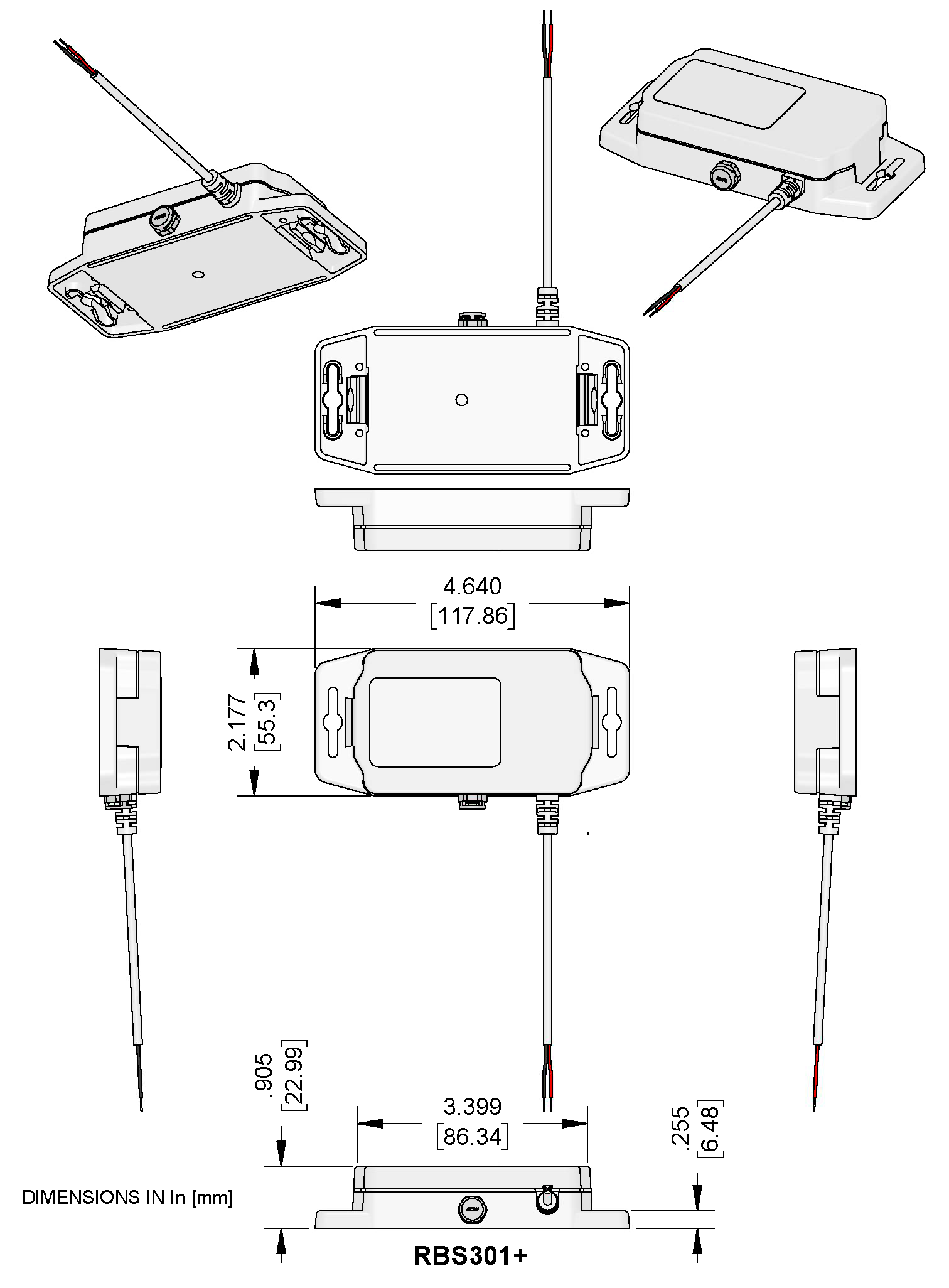
Mechanical Drawings
The mechanical drawings provided in this section are for the main body of the sensor. All dimensions use inches unless otherwise specified.
RBS301 Indoor Sensors

RBS301+ Sensors
RBS304 Push Button Sensor

RBS306 Outdoor/Industrial Sensors

Before Installation
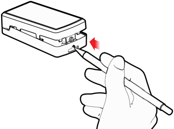
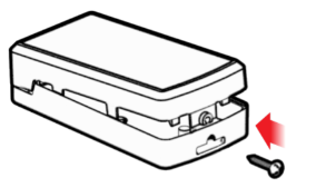
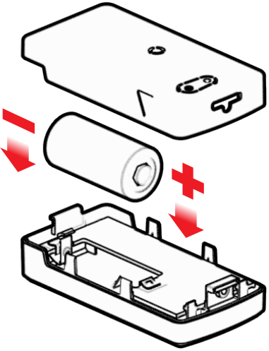
Prepare the Sensor
Sensors ship with batteries installed and a plastic tab over the battery, which needs to be removed before use. Pull the tab out of the sensor to connect the battery.
If you can't pull out the tab easily, refer to the solution that is relevant to your sensor in the following table.
| Sensor Type | Solution |
|---|---|
| RBS301 Sensor |
To remove the battery tab:
|
| RBS304 Sensor |
To remove the battery tab:
|
| RBS306 Sensor |
Important: Do NOT remove the
lid.
To remove the battery tab:
|
Add the Sensor to a Network
Your sensor can be used through either a third-party network or the console.
- To use a third-party network, refer to the Connecting LoRaWAN Sensors on Gateways and Networks (RB00001), which is available through the sensor page at https://www.multitech.com/products/sensors.
- To use the console, use the following steps.
The console shows complete when the device is successfully added.
Installation
Mounting the Sensor
Sensors are shipped with double-sided tape for mounting the sensor. Refer to the following table for the mounting instruction that is relevant to your sensor.
| Sensor Type | Solution |
|---|---|
| RBS301 Sensor |
Note: For Door/Window Sensors, refer to Mounting a Door/Window Sensor.
To mount the sensor:
|
| RBS301+ Sensor | To mount the sensor:
 Note:
If using VHB tape, MultiTech recommends applying the tape only to the rear of the device for mounting between the ear tabs. If using fasteners with the ear tabs to mount the device, see selecting the correct fastener type. |
| RBS304 Sensor |
To mount the sensor:
|
| RBS306 Sensor |
To mount the sensor:
|
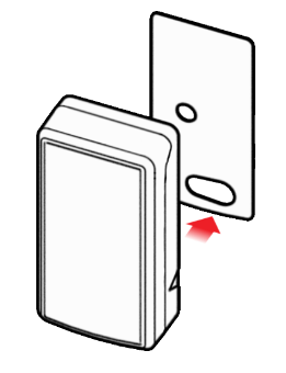
Mounting a Door/Window Sensor
The window/door sensor includes a sensor and a magnet that need to line up.
-
Use the included large adhesive pad to secure the sensor case on the
door/window frame with the triangular notch facing the door/window as
shown.


Selecting the Correct Fastener Type
Ensure you choose fasteners designed for your specific installation surface or material. Different substrates, for example metal, wood, plastic, drywall, masonry, or composite materials, demand fasteners that engineers designed for proper engagement, load distribution, corrosion resistance, and long-term performance. Using incompatible fasteners can compromise holding strength, trigger premature failure, or damage the installation surface.
- Screws should be steel or stainless steel.
- The screw head style can be a pan head, rounded head, or truss head. MultiTech does not recommend countersunk heads.
- The maximum diameter of the screw head is .375” or 9.5mm.
To prevent installation failures and reduce the risk of injury or equipment damage, always:
- Ensure all fasteners meet the requirements of the intended application.
- Choose fasteners designed for your specific installation surface or material.
- Use steel or other metal screws, as these provide the necessary strength, structural integrity, and resistance to deformation over time.
- Use the correct head sizes recommended by MultiTech to prevent fasteners from slipping out of the mounting tabs.
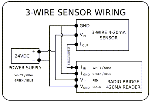
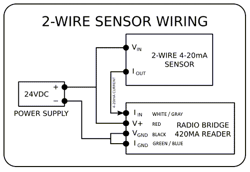
Wiring Diagrams for 4-20mA Current Loop Sensors
The following diagrams illustrate the wiring for 2, 3, and 4 wire systems.
| Wire Color | Function |
|---|---|
| Red | 5–24 VDC |
| Black | Ground |
| White/Gray | Current loop + |
| Green/Blue | Current loop − |

Installing Probe Water Sensors
Install the water sensor so the probe reaches an area where water leaks may occur, such as water heaters, standing tanks, windows/doors, toilets, septic systems, condenser and refrigeration systems, floor drains, or water control valves. The probe may be placed inside containers to detect water.
-
Secure the probe to the floor or wall using the small adhesive pad or with an
appropriately sized screw in any of the probe's wall or floor mounting
holes.
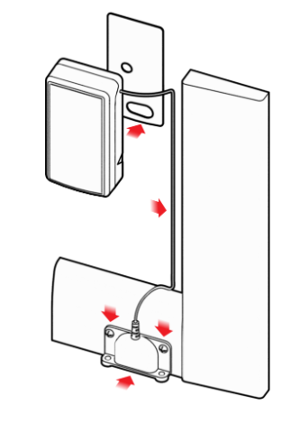
Installing Rope Water Sensors
Rope water sensors detect leaks along the length of the rope, it can be wrapped around a fixture or spread across a room, dropped ceiling, or anywhere you need leak detection. Install the sensor so the rope reaches the area you want to monitor for water leaks.
- Spread the rope into the area you want to monitor for leaks.
- Attach the sensor to a wall:
- For a indoor sensor, use the included large adhesive pad to secure the case to a wall.
- For an outdoor sensor, secure the sensor to a wall or floor with screws. Consult the mechanical drawing for hole dimensions.
- For best radio performance, avoid placing the sensor in another enclosure or in an area crowded with other equipment.
Message Protocol
This chapter defines the protocol and message definitions for all sensor uplinks and downlinks. Common messages are utilized by all devices and include uplinks such as error messages, tamper alerts, battery voltage and signal quality, as well as general device configuration downlinks. Each sensor also includes its own specific uplink reports and downlink configurations depending on the type of sensor(s) it uses.
Uplink Messages
This section details the structure of uplink messages (sensor to web application).
| Item | Length | Description |
|---|---|---|
| Protocol Version | 4 bits | A constant 1, provides extensibility to the specific format of a message type. |
| Packet Counter | 4 bits | Sequential Message Counter. Increments by one for each subsequent message. When it reaches 0xF (15 decimal), it wraps back to 0. This counter helps identify if a message is lost, out-of-order, or duplicated. |
| Message Type | 1 byte | Payload format is 8 bytes. Refer to next table. |
| Message Payload | 0-7 bytes | Each message type has between 0 and 8 bytes of payload data specific to the sensor. Refer to the following tables for payload information. |
Common Message Types
This section defines the protocol and message definitions common to all wireless sensors. Common messages include basic error messages, tamper, supervisory, link quality, and downlink acknowledgements but do not include sensor specific data.
| Message Type | Length | Description |
|---|---|---|
| 0x00 | 6 bytes | Reset Message. Sent once on power up of device. |
| 0x01 | 9 bytes | Supervisory Message. Sent at configurable time interval, typically once daily. Contains device status information including battery voltage. |
| 0x02 | 1 byte | Tamper Event. Sent if the case is opened or closed. |
| 0xFA | 9 bytes | Device Info Message. Sends bytes of the current configuration. |
| 0xFB | 3 bytes | Link Quality Message. Contains RSSI and SNR signal statistics as received by the sensor. |
| 0xFF | 1-9 bytes | Downlink Received Acknowledgement Message. Sent when a downlink is received successfully. |
Sensor Specific Messages
This section enumerates the uplink message type that are specific to the sensor type used by the device. Sensor specific messages contain metrics as measured by the various sensor probes, along with various types of alerts indicating a change in reading, threshold crossing, or report on periodic interval.
| Message Type | Length | Description |
|---|---|---|
| 0x03 | 1 byte | Door/Window Sensor Event |
| 0x06 | 2 bytes | Push Button Sensor Event |
| 0x07 | 1 byte | Dry Contact Sensor Event |
| 0x08 | 2 bytes | Water Leak Sensor Event |
| 0x09 | 3 bytes | Thermistor Temperature Sensor Event |
| 0x0A | 2 bytes | Tilt Sensor Event |
| 0x0D | 5 bytes | Air Temperature and Humidity Sensor Event |
| 0x0E | 1 bytes | Accelerometer-based Movement Sensor Event |
| 0x0F | 4 bytes | High-precision Tilt Sensor Event |
| 0x10 | 3 bytes | Ultrasonic Distance Sensor Event |
| 0x11 | 3 bytes | 4-20mA Current Loop Sensor Event |
| 0x13 | 4 bytes | Thermocouple Temperature Sensor Event |
| 0x14 | 3 bytes | Voltmeter Sensor Event |
| 0x19 | 3 bytes | CMOS Temperature Sensor Event |
Uplink Message Types
Reset Message (0x00)
The Reset Message is sent to the Cloud every time that the Sensor is Reset. The Reset Code has to do with the nature of the reset and is used by the factory for diagnostic purposes.
| Byte Position | Length | Description | ||||||||||||||||||||||||||||||||
|---|---|---|---|---|---|---|---|---|---|---|---|---|---|---|---|---|---|---|---|---|---|---|---|---|---|---|---|---|---|---|---|---|---|---|
| 0 | 1 byte | Device Type Code. A Product Identifier Code identifying the
specific hardware configuration of the device. Note these values do
not always correlate to sensor event types since the specific device
may include multiple sensor types. The below table shows currently
registered Device Type Codes:
|
||||||||||||||||||||||||||||||||
| 1 | 1 byte | Hardware Version. Human-readable byte containing two digit hardware version. Example: 0x27 would be hardware version 2.7 | ||||||||||||||||||||||||||||||||
| 2-3 | 2 bytes | Human-readable in firmware versions prior to 2.0, where 0x0103
would represent version 1.3. From 2.0 onward, the firmware version
is formatted as a three digit version number. Format
0
Format 1
|
||||||||||||||||||||||||||||||||
| 4-5 | 2 bytes | Processor-dependent Reset Code. Used only for factory diagnostics. |
Supervisory Message (0x01)
The wireless sensors will send a periodic supervisory message so that a backend system can verify that the device is still alive and to report error conditions. The supervisory message also contains a payload that contains the status (current) of the sensor.
| Byte Position | Length | Description | ||||||||||||||
|---|---|---|---|---|---|---|---|---|---|---|---|---|---|---|---|---|
| 0 | 1 byte | Device Error Codes. The Device Status Error Code byte is in the
following format:
|
||||||||||||||
| 1 | 1 byte | Current Sensor State. Reflects the state of various single-byte sensor readings, however sensor type is not indicated here. For readings of full sensor state at even time intervals, use the periodic reporting feature of the Sensor Configuration. | ||||||||||||||
| 2 | 1 byte | Battery Level. Human-readable byte containing two-digit battery voltage. Example: 0x29 would be 2.9 Volts. Since the lithium batteries do not discharge linearly, use the Battery Low bit from the Supervisory Error Code to signal battery replacement. | ||||||||||||||
| 3 | 4 bytes | Current Sensor State. Reflects the state of various multi-byte sensor readings, however sensor type is not indicated here. For readings of full sensor state at even time intervals, use the periodic reporting feature of the Sensor Configuration. | ||||||||||||||
| 7 | 2 bytes | Event Accumulation Count. The number of sensor events since last supervisory message. Use in combination with the "Disable All Sensor Messages" General Configuration Option to report sensor event totals rather than report events as they occur. Useful when only event frequency is desired. This feature also improves battery life and reduces communication traffic. |
Tamper Event (0x02)
The sensor will send a message when the tamper switch has been either opened or closed through either an enclosure tamper or a wall mount tamper. The tamper message contains a 1-byte payload as shown in the following table.
| Byte Position | Length | Description | ||||||
|---|---|---|---|---|---|---|---|---|
| 0 | 1 byte | The tamper switch is a hardware option available at time of
order. The device sends a message when device's enclosure has been
opened or closed, or when the enclosure has been forcibly removed
from its mounting position when secured with the included tamper screw.
|
Door/Window Event (0x03)
| Byte Position | Length | Description | ||||||
|---|---|---|---|---|---|---|---|---|
| 0 | 1 byte | Change in status of the magnet-activated hall-effect sensor.
Reports closed when the included magnet is in proximity to the device.
|
Pulse Counter Message (0x04)
The pulse message will always contain the overall pulse count from power on. The pulse count will reset when the battery is changed. Pulse rates are in pulses per minute (PPM).
| Byte Position | Bit Position | Description | ||||||||||
|---|---|---|---|---|---|---|---|---|---|---|---|---|
| 0 | 7-5 | Event type
|
||||||||||
| 0 | 4-3 | Unused | ||||||||||
| 0 | 2-0 | Fractional rate (in units of 1/8 PPM) (for example, 010 --> .25) | ||||||||||
| 1 | 7-0 | Pulse rate integer (least significant 8 bits) | ||||||||||
| 2 | 7-3 | Pulse rate integer (most significant 5 bits) | ||||||||||
| 2 | 2-0 | Pulse count bits (upper [34:32] bits) | ||||||||||
| 3-6 | All | Pulse count bits (lower [31:0] bits) |
Example:
14 04 22 33 34 44 44 44 44
| Protocol | Packet count | Pulse_ID | Byte 0 | Byte 1 | Byte 2 | Byte 3 | Byte 4 | Byte 5 | Byte 6 |
|---|---|---|---|---|---|---|---|---|---|
| 1 | 4 | 04 | 22 | 33 | 34 | 44 | 44 | 44 | 44 |
| Protocol | Packet# | Message type | Event type | Fractional rate | Pulse rate integer | Pulse count [34:0] |
|---|---|---|---|---|---|---|
| 1 | 4 | Pulse Counter | Overspeed | 0.25 | 1587 | 18325193796 |
Push Button Event (0x06)
| Byte Position | Length | Description | ||||||||
|---|---|---|---|---|---|---|---|---|---|---|
| 0 | 1 byte | Button Identifier of the button pressed
|
||||||||
| 1 | 1 byte | The action performed on the button pressed.
|
Dry Contact Event (0x07)
| Byte Position | Length | Description | ||||||
|---|---|---|---|---|---|---|---|---|
| 0 | 1 byte | Change in status of the connection between the contacts
|
Water Event (0x08)
| Byte Position | Length | Description | ||||||
|---|---|---|---|---|---|---|---|---|
| 0 | 1 byte | Change in status of the conductance across the water probe or rope
|
||||||
| 1 | 1 byte | Analog measurement of the conductance between probes (scale of 0-255). Used to verify conductance of the fluid being detected. Various fluids may not be identified using this measurement, although this number may help with event filtering by the application. |
Thermistor Temp Event (0x09)
| Byte Position | Length | Description | ||||||||||||
|---|---|---|---|---|---|---|---|---|---|---|---|---|---|---|
| 0 | 1 byte | Reporting event type
|
||||||||||||
| 1 | 1 byte | Current temperature in degrees Celsius. When a temperature is out of range, the system reports it as 0x7F (highest positive signed number) on the high end and 0x80 on the low end. |
Tilt Event (0x0A)
| Byte Position | Length | Description | ||||||||||
|---|---|---|---|---|---|---|---|---|---|---|---|---|
| 0 | 1 byte | Reporting event type
|
||||||||||
| 1 | 1 byte | Angle of tilt from vertical axis in degrees (scale of 0-180) |
Air Temp and Humidity Event (0x0D)
| Byte Position | Length | Description | ||||||||||||||||||||
|---|---|---|---|---|---|---|---|---|---|---|---|---|---|---|---|---|---|---|---|---|---|---|
| 0 | 1 byte | Reporting event type
|
||||||||||||||||||||
| 1 | 1 byte | Integer portion of current temperature in degrees Celsius. The temperature value is a signed byte, where the first bit indicates the sign. For example, 0x10 means +16° C and 0x90 means -16° C. | ||||||||||||||||||||
| 2 | 1 byte | Decimal portion of current temperature in tenths of a degree Celsius. Note that only the upper four bits are used and range from 0x00 through 0x90. For example, if the value is 0x60 this represents 0.6 degrees. | ||||||||||||||||||||
| 3 | 1 byte | Integer portion of current percent relative humidity. This is always a positive integer. For example, if the value is 0x16, this represents 22%RH. | ||||||||||||||||||||
| 4 | 1 byte | Decimal portion of current tenths of a percent relative humidity. Note that only the upper four bits are used and range from 0x00 through 0x90. For example, if the value is 0x30 this represents 0.3%RH. |
Accelerometer-based Movement (0x0E)
| Byte Position | Length | Description | ||||||
|---|---|---|---|---|---|---|---|---|
| 0 | 1 byte | The accelerometer has detected movement exceeding its sensitivity threshold.
|
High-precision Tilt Event (0x0F)
| Byte Position | Length | Description | ||||||||||||
|---|---|---|---|---|---|---|---|---|---|---|---|---|---|---|
| 0 | 1 byte | Reporting event type
|
||||||||||||
| 1 | 1 byte | Integer portion of the tilt angle in degrees. Note this is always a positive number ranging from 0-180. For example, if the value is 0x31, the angle is 49 degrees. | ||||||||||||
| 2 | 1 byte | Decimal portion of the tilt angle in tenths of a degree. Note that only the upper four bits are used and range from 0x00 through 0x90. For example, if the value is 0x40 this represents 0.4 degrees. | ||||||||||||
| 3 | 1 byte | Temperature in degrees Celsius. The temperature value is a signed byte, where the first bit indicates the sign. For example, 0x10 means +16° C and 0x90 means -16° C. |
Ultrasonic Distance Event (0x10)
| Byte Position | Length | Description | ||||||||||||
|---|---|---|---|---|---|---|---|---|---|---|---|---|---|---|
| 0 | 1 byte | Reporting event type
|
||||||||||||
| 1 | 2 bytes | Current distance in millimeters. This is a 16-bit positive integer. For example, if the value is 0x0282, the distance is 642mm. This full range of this value can vary with the type of ultrasonic probe being used. |
4-20mA Current Loop Event (0x11)
| Byte Position | Length | Description | ||||||||||||
|---|---|---|---|---|---|---|---|---|---|---|---|---|---|---|
| 0 | 1 byte | Reporting event type
|
||||||||||||
| 1 | 2 bytes | Analog measurement of current loop in units of 10mA. This is a 16-bit positive integer ranging from 400-2000. For example, if the value is 0x0385, the current is 9.01mA. |
Thermocouple Temperature Event (0x13)
| Byte Position | Length | Description | ||||||||||||||||||
|---|---|---|---|---|---|---|---|---|---|---|---|---|---|---|---|---|---|---|---|---|
| 0 | 1 byte | Reporting event type
|
||||||||||||||||||
| 1 | 2 bytes | Current Temperature in degrees Celsius. Decoded by taking the 16-bit two’s complement number and multiplying by 1/16th. For example, if the value is 0x55C0 the temperature is 1372.00 degrees C. A value of 0xF060 would be -250.00 degrees. | ||||||||||||||||||
| 2 | 1 byte | Fault code
|
Voltage Event (0x14)
| Byte Position | Length | Description | ||||||||||||
|---|---|---|---|---|---|---|---|---|---|---|---|---|---|---|
| 0 | 1 byte | Reporting event type
|
||||||||||||
| 1 | 2 bytes | Voltage measurement in units of 10mV. This is a 16-bit positive integer ranging from 0-3000. For example, a value of 0x512 would be 12.98VDC. |
CMOS Temperature Event (0x19)
| Byte Position | Length | Description | ||||||||||||
|---|---|---|---|---|---|---|---|---|---|---|---|---|---|---|
| 0 | 1 byte | Reporting event type
|
||||||||||||
| 1 | 1 byte | Integer portion of current temperature in degrees Celsius. The temperature value is a signed byte, where the first bit indicates the sign. For example, 0x10 means +16° C and 0x90 means -16° C. | ||||||||||||
| 2 | 1 byte | Decimal portion of current temperature in tenths of a degree Celsius. Note that only the upper four bits are used and range from 0x00 through 0x90. For example, if the value is 0x60 this represents 0.6 degrees. |
Device Info Message (0xFA)
| Byte Position | Length | Description |
|---|---|---|
| 0 | 1 byte | Index of Device Configuration out of total number of Configuration Messages. Human-readable byte. 0x15 reads as message 1 of 5, 0x25 is message 2 of 5, and so on. |
| 1 | 8 bytes | Bytes of the configuration (see Downlinks section). The bytes as positioned may be sent as-is in the form of a downlink to provide the same configuration to similar devices. |
Link Quality Message (0xFB)
The link quality message provides a signal strength and signal to noise measurement at the device itself. The payload of the link quality message is shown in the following table.
| Byte Position | Length | Description |
|---|---|---|
| 0 | 1 byte | Current Sub-Band, sub-band currently joined and used for communication to the gateway and network server. Value ranges from 1-8 for US915. For other regions, value depends on available channels. |
| 1 | 1 byte | RSSI of last DOWNLINK received, signed integer format values in bytes 1 and 2 in two’s complement format. |
| 2 | 1 byte | SNR of last DOWNLINK received, signed integer format values in bytes 1 and 2 in two’s complement format. |
Downlink ACK (0xFF)
| Byte Position | Length | Description | ||||||||||
|---|---|---|---|---|---|---|---|---|---|---|---|---|
| 0 | 1 byte | Acknowledgement and result of downlink received
|
||||||||||
| 1 | 8 bytes | Valid downlink bytes as received. Follows 0x03 in first byte only. |
Downlink Messages
A downlink message is one that is sent to the sensor from the cloud and is used to configure the sensor itself. Messages cannot be initiated from the cloud since the sensor is typically sleeping and the radio is turned off, so the sensor itself must initiate a downlink message.
| Item | Length | Description |
|---|---|---|
| Config Type | 1 byte | The type of configuration corresponding to general sensor behavior, sensor specific behavior, or advanced features. See configuration types. |
| Config Payload | 7 bytes | The bytes comprising the configuration. All downlinks sent to the device must define all byte positions -- partial configurations within a downlink message are not allowed. Each downlink sent must total 8 bytes in length including the config type and any remaining byte positions should be padded with zeros. |
Common Configuration Types
| Item | Length | Description |
|---|---|---|
| 0x01 | 4 bytes | General Configuration |
| 0xEC | 0 bytes | Restore All Factory Defaults (Firmware 3.0 or newer) |
| 0xED | 1 byte | Device Info Request (Firmware 3.0 or newer) |
| 0xEE | 1 byte | Link Quality Configuration (Firmware 3.0 or newer) |
| 0xEF | 4 bytes | ADR Advanced Configuration (Firmware 3.0 or newer) |
| 0xFC | 3 bytes | Advanced Configuration |
Sensor Configuration Types
| Item | Length | Description |
|---|---|---|
| 0x03 | 5 bytes | Door/Window Sensor Configuration |
| 0x06 | 3 bytes | Push Button Sensor Configuration |
| 0x07 | 5 bytes | Dry Contact Sensor Configuration |
| 0x08 | 3 bytes | Water Sensor Configuration |
| 0x09 | 7 bytes | Thermistor Temperature Sensor Configuration |
| 0x0A | 7 bytes | Tilt Sensor Configuration |
| 0x0D | 7 bytes | Air Temp and Humidity Sensor Configuration |
| 0x0E | 4 bytes | Accelerometer-based Motion Sensor Configuration |
| 0x0F | 7 bytes | High-precision Tilt Sensor Configuration |
| 0x10 | 7 bytes | Ultrasonic Distance Sensor Configuration |
| 0x11 | 7 bytes | 4-20mA Current Loop Sensor Configuration |
| 0x13 | 7 bytes | Thermocouple Temperature Sensor Configuration |
| 0x14 | 7 bytes | Voltmeter Sensor Configuration |
| 0x20 | 4 bytes | Shake-to-send Configuration (Firmware 3.0 or newer) |
Downlink Message Types
General Configuration (0x01)
The general configuration command is used for configuration parameters that apply to all sensor types. This command is defined in the following table.
| Byte Position | Length | Description | ||||||||||||||||
|---|---|---|---|---|---|---|---|---|---|---|---|---|---|---|---|---|---|---|
| 0 | 1 byte | Disable all sensor events. When the sensor events are disabled supervisory and tamper-open will still send messages, but sensor events will not. Setting this bit to 1 will disable new event messages and setting to 0 will re-enable sensor event messages. | ||||||||||||||||
| 1 | 1 byte | Radio Configuration. The Radio config byte is defined in the
following table.
|
||||||||||||||||
| 2 | 1 byte | Supervisory period. Default 19 hours. The supervisory period from the
general configuration command controls the time between supervisory
messages as defined in the following table.
|
||||||||||||||||
| 3 | 1 byte | Sampling Rate. Controls the rate at which the device wakes up out of
low power sleep mode to check the state of the sensor. Note, this is
not the same as the rate at which the device reports a reading over
radio. By increasing the time between samples, the battery life can be
greatly increased. Note that the sampling period only applies to sensors
that take scaled measurements like temperature and tilt. It does not
apply to sensors with binary inputs such as door/window sensors or push
buttons. A value of 0 in this field leaves the sampling rate at the
current value and for any non- zero value the sampling rate can be
determined by the following table:
|
Door/Window Sensor Configuration (0x03)
| Byte Position | Length | Description | ||||||||
|---|---|---|---|---|---|---|---|---|---|---|
| 0 | 1 byte | Disable events (see the table Disable Events Bit Definitions).
|
||||||||
| 1-2 | 2 bytes | Open hold time. The hold times are 16-bit values that represent the amount of time the sensor must be held in a particular position (open or closed) before a message is sent. The hold time values range from 1-65535 and are represented in 250ms increments. This gives the hold times a range of 250 milliseconds – 4.5 hours. If the hold time is 0, the feature is disabled and an alert will be sent any time the state changes. | ||||||||
| 3-4 | 2 bytes | Close hold time. |
Pulse Counter Message (0x04)
Through the Pulse downlink all the reporting types can be disabled or enabled. Restoral margin is a hysteresis setting to prevent “chatter” if you are hovering around a value.
| Byte Position | Bit Position | Description |
|---|---|---|
| 0 | 7 | Periodic reporting units: 0=Hours, 1=Minutes |
| 0 | 6-0 | Periodic reporting value: 0-127, 0 disables |
| 1 | 7-4 |
Threshold sample size (groups of 5) 5-75, 0 disables Threshold Sample Size: Related to the Overspeed and Underspeed Threshold settings, the sensor waits until it observes this many consecutive pulses occurring above the Overspeed Threshold or below the Underspeed Threshold rates before generating the appropriate pulse-speed-alert uplink. The user-entered value of this field is interpreted as multiples of 5. If the user enters 1, the Threshold Sample Size is set to 5; if 2 is entered, the Threshold Sample Size is set to 10 and so on. Setting this field to zero achieves the same configuration as setting it to 1. Example: (04802000020000000D) If the user enters 2 in this field, the Threshold Sample Size is set to 10. If the user has set Overspeed Threshold to 2 (encoding for 2 Pulses Per Minute), the sensor will wait to send a pulse-overspeed-alert uplink until 10 pulses have come in at a rate of 2 pulses per minute. If 9 pulses come in at a rate of 2 PPM, and then a 10th pulse comes in 5 minutes later, no pulse-overspeed-alert uplinks will be generated. A similar convention would apply to pulses occurring at a frequency at or below the Underspeed Threshold rate. |
| 1 | 3-0 |
Restoral margin (PPM) 1-15, 0 disables Restoral Margin (Pulses Per Minute): The Restoral Margin is used for the over and underspeed thresholds to cross back over the threshold a certain amount before a new event is reported. This prevents excessive event messages if the Pulse rate (PPM) is at or near the threshold. For example, consider an overspeed pulse rate threshold set at 20 Pulses per Minute and the restoral margin set at 5. If the pulse rate exceeds 20 PPM then an event is generated and a message is sent to the network. The pulse rate must now drop to 15 PPM and then meet or exceed 20 PPM before another overspeed event is reported. The restoral margins are unsigned values with units of 1 PPM (range is 0-15 PPM). If a restoral margin is set to 0, it is disabled. |
| 2 | 7-5 | Unused |
| 2 | 4-0 |
Overspeed threshold (PPM), most significant bit Overspeed Threshold (Pulses Per Minute): An upper speed limit for the rate at which pulses are occurring. When the sensor detects pulses occurring at a frequency (pulses per minute) that meets or exceeds this limit, the device sends a pulse-overspeed-alert uplink. When the user has entered zero for this field, there is no upper speed limit on pulse rate; no pulse-overspeed-alert uplinks will be generated regardless of how rapidly pulses are occurring. Example: 04800000190000000D = Overspeed threshold of 25ppm This example will send a message when 25 or more pulses are sensed in 1 minute. The alert will not be repeated if the pulse rate stays above the threshold. If the pulse rate falls below the overspeed threshold but then goes above the threshold again, another alert will be sent. |
| 3 | 7-0 | Overspeed threshold, least significant bit, 0 in bytes 2-3 disables |
| 4 | 7-5 | Unused |
| 4 | 4-0 |
Underspeed threshold (PPM), most significant bit Underspeed Threshold (Pulses Per Minute): Like the overspeed threshold, but a lower speed limit instead of upper. When the sensor detects pulses occurring at a frequency that meets or falls below this limit, the device sends a pulse-underspeed-alert uplink. When the user has entered zero for this field, there is no lower speed limit on pulse rate; no pulse-underspeed-alert uplinks will be generated regardless of how slowly pulses are occurring. Example: 04800000000014000D = Underspeed threshold of 20ppm This example will send a message when the 20 or fewer pulses are sensed in 1 minute. The alert will not be repeated if the pulse rate stays below the threshold. If the pulse rate goes above the underspeed threshold but then goes below the threshold again, another alert will be sent. |
| 5 | 7-0 | Underspeed threshold, least significant bit, 0 in bytes 4-5 disables |
| 6 | 7 |
Too-long inactive interval units: 0=Seconds, 1=Minutes Too-Long Inactive: This field configures the Too-Long Inactive time interval. If this field is set to a nonzero value, the sensor will begin a countdown each time a pulse is detected. If that count down expires before another pulse is detected, the sensor will generate a pulse-too-long-alert uplink. If this field is set to 0, this feature is disabled and no pulse-too-long-alert uplinks will ever be sent regardless of how long the sensor waits between pulses. Example: (04800000000000850D) If Too-Long Inactive is set to 5 minutes, and a pulse is detected, the sensor starts a 5 minute timer. If a new pulse is detected at 4 minutes and 59 seconds after the previous pulse, no alert is generated and the timer restarts. If an additional 5 minutes pass after this newer pulse was detected, a pulse-too-long-alert uplink is generated. |
| 6 | 6-0 | Too-long inactive value: 0-127, 0 disables |
| 7 | 7-0 |
Debounce delay (increments of 5ms) 0-1275ms, 0 = leave unchanged Debounce Delay: This field sets the length of a relatively short time interval, after a pulse is detected, during which the sensor ignores any noise that could be mistaken for a pulse. The appropriate setting for this field depends on the pulse source the user is trying to use the sensor to observe. If the user believes the sensor is reporting less pulses than what has been generated, they should try lowering this field’s value. If the user believes the sensor is reporting more pulses than what has been generated, they should try raising this field’s value. Example: (048F00000000000005 {15min periodic reporting}) If the user has a water meter that is known to generate pulses at a maximum rate of 2 Pulses Per Minute, but is also known to have a noisy switch that bounces for 5-20 milliseconds after a proper pulse generation, an appropriate setting for the debounce delay would be 25 milliseconds. |
Default Downlink: 048F0000000000000D (15 min reporting period, all alerts disabled, 65ms debounce delay)
Example:
04 CA 53 03 E8 01 2C 9E 1E
| Pulse_ID | Byte 0 | Byte 1 | Byte 2 | Byte 3 | Byte 4 | Byte 5 | Byte 6 | Byte 7 |
|---|---|---|---|---|---|---|---|---|
| 04 | CA | 53 | 03 | E8 | 01 | 2C | 9E | 1E |
| Reporting period interval | Periodic reporting value | Threshold sample size (groups of 5) | Restoral margin | Overspeed threshold | Underspeed threshold | Too- long time interval | Too- long value | Debounce delay |
|---|---|---|---|---|---|---|---|---|
| Minutes | 74 | 25 | 3 | 1000 | 300 | Minutes | 30 | 150 |
Push Button Configuration (0x06)
| Byte Position | Length | Description | ||||||||||
|---|---|---|---|---|---|---|---|---|---|---|---|---|
| 0 | 1 byte | Disable events (see the table Disable Events Bit Definitions).
|
||||||||||
| 1 | 1 byte | Hold Delay. The hold delay defines the amount of time the button must be held before a button held event is sent. The field can range from 0-20 in 250ms increments (0-5 seconds). If set to 0 then the hold delay will not send an event message. | ||||||||||
| 2 | 1 byte | LED Configuration. For the blink after send, note that if a
message is confirmed (acknowledgements) then the blink occurs after
the message is sent and an ack is received. If the message is
unconfirmed (no acknowledgements) then the blink occurs after the
message is sent. The behavior of the LED can be controlled through
the LED configuration byte defined in the following table.
|
Dry Contact Sensor Configuration (0x07)
| Byte Position | Length | Description | ||||||||
|---|---|---|---|---|---|---|---|---|---|---|
| 0 | 1 byte | Disable events (see the table Disable Events Bit Definitions).
|
||||||||
| 1-2 | 2 bytes | Contacts shorted hold time. The hold times are 16-bit values that represent the amount of time the sensor must be held in a particular position (open or closed) before a message is sent. The hold time values range from 1-65535 and are represented in 250ms increments. This gives the hold times a range of 250 milliseconds – 4.5 hours. If the hold time is 0, the feature is disabled and an alert will be sent any time the state changes. | ||||||||
| 3-4 | 2 bytes | Contacts opened hold time. |
Water Leak Sensor Configuration (0x08)
| Byte Position | Length | Description | ||||||||
|---|---|---|---|---|---|---|---|---|---|---|
| 0 | 1 byte | Disable events (see the table Disable Events Bit Definitions).
|
||||||||
| 1 | 1 byte | Threshold of relative resistance of the water probe/rope. The range of the measurement is 0-255, default is 80. It is not recommended to change this setting. Water detection will generally far exceed this threshold when wet, and fall far below when dry. This value can not be used to determine the fluid being detected and is not a means to adjust sensitivity. False alerts or undesired detections should be addressed by fine tuning the installation positioning and avoiding contact of the probe with conductive materials. | ||||||||
| 2 | 1 byte | Restoral margin. An alert is sent when the relative measurement increases above the defined threshold. The restoral margin requires that the measurement reduces by a certain amount below the threshold before another alert is triggered. Both the threshold and restoral margin are in units of relative resistance measurements on a scale of 0-255. The default is 0. It is not recommended to alter this setting. |
Thermistor Temp Configuration (0X09)
| Byte Position | Length | Description | ||||||||||||
|---|---|---|---|---|---|---|---|---|---|---|---|---|---|---|
| 0 | 1 byte | Reporting Mode.
|
||||||||||||
| 1 | 1 byte | Periodic Reporting Time Interval (0 = disable periodic reporting).
|
||||||||||||
| 2 | 1 byte | Restoral Margin (Threshold Mode only). The Restoral Margin is used for the upper and lower thresholds and requires the temperature value to cross back over the threshold by this amount before a new event is reported. This prevents excessive event messages if the temperature is at or near the threshold. For example, consider an upper temp threshold set at 30 degrees Celsius and the restoral margin set at 5 degrees. If the temperature initially exceeds 30 degrees then an event is generated and a message is sent to the network. The temperature must now drop to 25 degrees and then exceed 30 degrees before another event is reported. The restoral margins are unsigned values with units of 1 degree Celsius (range is 1-15 degrees C). If a restoral margin is set to 0, it is disabled. | ||||||||||||
| 3 | 1 byte | Absolute Temperature for Lower Threshold (Threshold Mode) or Relative Temperature Increase (Report on Change Mode). | ||||||||||||
| 4 | 1 byte | Absolute Temperature for Upper Threshold (Threshold Mode) or Relative Temperature Decrease (Report on Change Mode). |
Tilt Sensor Configuration (0X0A)
| Byte Position | Length | Description | ||||||||||||
|---|---|---|---|---|---|---|---|---|---|---|---|---|---|---|
| 0 | 1 byte | Disable events (see table Disable Event Bit Definitions).
|
||||||||||||
| 1 | 1 byte | Angle for transition to horizontal state in degrees. Default 55 degrees. The angle in bytes 1 and 2 define the angle in degrees off of the vertical axis that the sensor needs to be tilted to generate an alert. For example, if the sensor is used to detect garage open/close events, the vertical threshold might be set at 35 degrees and the horizontal threshold may be set at 55 degrees. It is not recommended to set both to the same values (both at 45 degrees for instance) since this may generate multiple alerts when it is oriented near the threshold. The range for each threshold is 0-90 degrees where 0 is completely vertical and 90 is completely horizontal. | ||||||||||||
| 2 | 1 byte | Angle for transition to vertical state in degrees. Default 35 degrees. | ||||||||||||
| 3 | 1 byte | Vertical hold time. The hold times are 8-bit values that represent the amount of time the tilt sensor must be held in a particular orientation before a message is sent. The hold time values range from 1-255 and are represented in 250ms increments. This gives the hold times a range of 250 milliseconds – 1 minute. If the hold time is 0, the feature is disabled and an alert will be sent any time the orientation changes. | ||||||||||||
| 4 | 1 byte | Horizontal hold time. | ||||||||||||
| 5 | 1 byte | Report-on-change toward vertical (0-90 degrees). The report-on-change feature will create an alert when the angle of the tilt increases or decreases by a specified amount. This allows for detecting a tilt when the initial orientation is not completely vertical. For example, one could place the sensor on a telephone pole and set a report-on-change event for 10 degrees. This configuration will send an alert if the pole leans another 10 degrees from its current position. The minimum value for the report-on-change angle is 5 degrees. A setting less than this will disable the feature. | ||||||||||||
| 6 | 1 byte | Report-on-change toward horizontal (0-90 degrees). |
Air Temp and Humidity Configuration (0X0D)
| Byte Position | Length | Description | ||||||||||||
|---|---|---|---|---|---|---|---|---|---|---|---|---|---|---|
| 0 | 1 byte | Reporting Mode.
|
||||||||||||
| 1 | 1 byte | Periodic Reporting Time Interval (0 = disable periodic reporting).
|
||||||||||||
| 2 | 1 byte | Restoral Margin (Threshold Mode only). The Restoral Margin is used for the upper and lower thresholds and requires the temperature or humidity values to cross back over the threshold a certain amount before a new event is reported. This prevents excessive event messages if the measurement is at or near the threshold. For example, consider an upper temp threshold set at 30 degrees Celsius and the restoral margin set at 5 degrees. If the temperature initially exceeds 30 degrees then an event is generated and a message is sent to the network. The temperature must now drop to 25 degrees and then exceed 30 degrees before another event is reported. The restoral margins are unsigned values with units of 1 degree Celsius (range is 1-15 degrees C) and 1% relative humidity (range is 1%-15%). If a restoral margin is set to 0, it is disabled. | ||||||||||||
| 3 | 1 byte | Absolute Temperature for Lower Threshold (Threshold Mode) or Relative Temperature Increase (Report on Change Mode). Default Threshold 10 degrees C. | ||||||||||||
| 4 | 1 byte | Absolute Temperature for Upper Threshold (Threshold Mode) or Relative Temperature Decrease (Report on Change Mode). Default Threshold 40 degrees C. | ||||||||||||
| 5 | 1 byte | Absolute Humidity for Lower Threshold (Threshold Mode) or Relative Humidity Increase (Report on Change Mode). Default Threshold 40% relative humidity. | ||||||||||||
| 6 | 1 byte | Absolute Humidity for Upper Threshold (Threshold Mode) or Relative Humidity Decrease (Report on Change Mode). Default Threshold 60% relative humidity. |
Accelerometer-based Motion Configuration (0X0E)
| Byte Position | Length | Description | ||||||||||
|---|---|---|---|---|---|---|---|---|---|---|---|---|
| 0 | 1 byte | Disable events (see table Disable Event Bit Definitions).
|
||||||||||
| 1 | 1 byte | Acceleration Scaling Factor. The scaling parameter defines the
G-force (1g is the force of gravity) range that the internal
accelerometer operates with, and the lower settings will be more
sensitive than higher settings. The threshold setting will have
units based on the scaling factor as shown in the table above. For
example, if the scaling is set to +/- 2g (2x the force of gravity),
then the threshold setting can be multiplied by 0.016g to calculate
the total G-force threshold. The accelerometer is measured every
250ms and if the difference between two consecutive measurements
exceeds the threshold, then a message is sent. The minimum setting
for the acceleration change threshold is 5. If a lower number is
programmed, the sensor will not generate an event. Note: For best
practice, use the largest scaling factor that the system will allow
and the smallest threshold. For example, use a threshold of 5 with
scaling factor 4g instead of threshold of 10 with 2g.
|
||||||||||
| 2 | 1 byte | Settling Time. In order to prevent continuous reporting of movement events, a “settling window” is used to ensure movement has stopped before the sensor reports a new event. In other words, the settling window defines the amount of time where the acceleration of all axis must stop changing before the sensor will report another event. The settling window time sets has units of 250ms increments (range of 250ms to 63 seconds). The default settling window is 5 seconds. | ||||||||||
| 3 | 1 byte | Acceleration Change Threshold for any/all axes. This will relate to the Units for Threshold values determined by the Scaling Factor. Range 0 - 127. |
High-precision Tilt Sensor Configuration (0X0F)
| Byte Position | Length | Description | ||||||||||||
|---|---|---|---|---|---|---|---|---|---|---|---|---|---|---|
| 0 | 1 byte | Reporting Mode.
|
||||||||||||
| 1 | 1 byte | Periodic Reporting Time Interval (0 = disable periodic reporting).
|
||||||||||||
| 2 | 1 byte | Hold Time. The hold time is an 8-bit value that represent the amount of time the tilt sensor must be held in a particular orientation (or exceeding a particular threshold) before a message is sent. This is a way to add extra “debounce” to the sensor so that it does not send excessive messages oscillating around a threshold. The hold time values range from 1-255 and are represented in 250ms increments. This gives the hold times a range of 250 milliseconds – 1 minute. If the hold time is 0, the feature is disabled and an alert will be sent any time the orientation changes. | ||||||||||||
| 3 | 1 byte | Angle for transition away from the 0-degree vertical state, whole integer value, default = 55 degrees (Threshold Mode). Angle for report-on-change mode away from 0-degree vertical position (toward the 180 degree inverted position), whole integer value (Report on Change Mode). | ||||||||||||
| 4 | 1 byte | Angle for transition away from the 0-degree vertical state, fractional value (Threshold Mode). Angle for report-on-change mode away from 0-degree vertical position, fractional value (Report on Change Mode). | ||||||||||||
| 5 | 1 byte | Angle for transition toward the 0-degree vertical state, whole integer value, default 35 degrees (Threshold Mode). Angle for report-on-change mode toward the 0-degree vertical position, whole integer value (Report on Change Mode). | ||||||||||||
| 6 | 1 byte | Angle for transition toward the 0-degree vertical state, fractional value (Threshold Mode). Angle for report-on-change mode toward the 0-degree vertical position, fractional value (Report on Change Mode). |
Ultrasonic Distance Configuration (0X10)
| Byte Position | Length | Description | ||||||||||||
|---|---|---|---|---|---|---|---|---|---|---|---|---|---|---|
| 0 | 1 byte | Reporting Mode.
|
||||||||||||
| 1 | 1 byte | Periodic Reporting Time Interval (0 = disable periodic reporting).
|
||||||||||||
| 2 | 1 byte | Hold Time. The purpose of the hold time is to add “debounce” or
“hysteresis” to the sensor so that it does not send rapid events
when the measurements are sitting close to the threshold. The
measurements for the ultrasonic may jump between multiple values if
it is not mounted properly, and thus if the measurement continuously
jumps above and below a threshold, it will send a flood of threshold
events without any hold time defined. For example, if the lower
threshold for the ultrasonic is set to 1000 (1 meter) and the
distance measurements are bouncing between say 900 and 1100 every 1
second, then there will be a lower threshold event every 2 seconds.
If a hold time of 10 seconds is defined, no threshold events occur.
The measurement must then drop below 1000 and stay below that
threshold for 10 seconds before a lower threshold event message is created.
|
||||||||||||
| 3 | 1 byte | Lower distance threshold in mm, upper byte. Default 100mm (Threshold Mode). Distance increase in mm, upper byte (Report on Change Mode). | ||||||||||||
| 4 | 1 byte | Lower distance threshold in mm, upper byte. Default 100mm (Threshold Mode). Distance increase, lower byte (Report on Change Mode). | ||||||||||||
| 5 | 1 byte | Upper distance threshold in mm, upper byte. Default 1000mm (Threshold Mode). Distance decrease in mm, upper byte (Report on Change Mode). | ||||||||||||
| 6 | 1 byte | Upper distance threshold in mm, lower byte (Threshold Mode). Distance decrease in mm, lower byte (Report on Change Mode). |
4-20mA Current Loop Configuration (0x11)
| Byte Position | Length | Description | ||||||||||||
|---|---|---|---|---|---|---|---|---|---|---|---|---|---|---|
| 0 | 1 byte | Reporting Mode.
|
||||||||||||
| 1 | 1 byte | Periodic Reporting Time Interval (0 = disable periodic reporting).
|
||||||||||||
| 2 | 1 byte | Restoral Margin (Threshold Mode only). The Restoral Margin is used for the upper and lower thresholds and requires the measurement value to cross back over the threshold a certain amount before a new event is reported. This prevents excessive event messages if the measurement is at or near the threshold. For example, consider an upper threshold set at 15mA and the restoral margin set at 1mA. If the measurement initially exceeds 15mA then an event is generated and a message is sent to the network. The measurement must now drop to 14mA and then exceed 15mA before another event is reported. The restoral margins are unsigned values with units of 10uA (range is 10uA-2.55mA). If a restoral margin is set to 0, it is disabled. | ||||||||||||
| 3-4 | 2 bytes | Lower analog measurement threshold. Default 8mA (Threshold Mode). Analog measurement increase (Report on Change Mode). | ||||||||||||
| 5-6 | 2 bytes | Upper analog measurement threshold. Default 16mA (Threshold Mode). Analog measurement decrease (Report on Change Mode). |
Thermocouple Temperature Configuration (0x13)
| Byte Position | Length | Description | ||||||||||||||||||||||||||||||||||||
|---|---|---|---|---|---|---|---|---|---|---|---|---|---|---|---|---|---|---|---|---|---|---|---|---|---|---|---|---|---|---|---|---|---|---|---|---|---|---|
| 0 | 1 byte | Reporting Mode and Thermocouple Probe Type. Although the sensor
comes with a K-type thermocouple by default, there are several
common thermocouple types are supported. Bits 4:1 in byte 0 define
the type as shown in the table below.
|
||||||||||||||||||||||||||||||||||||
| 1 | 1 byte | Periodic Reporting Time Interval (0 = disable periodic reporting).
|
||||||||||||||||||||||||||||||||||||
| 2 | 1 byte | Restoral Margin (Threshold Mode only). The Restoral Margin is used for the upper and lower thresholds and requires the temperature value to cross back over the threshold a certain amount before a new event is reported. This prevents excessive event messages if the temperature is at or near the threshold. For example, consider an upper temp threshold set at 30 degrees Celsius and the restoral margin set at 5 degrees. If the temperature initially exceeds 30 degrees then an event is generated and a message is sent to the network. The temperature must now drop to 25 degrees and then exceed 30 degrees before another event is reported. The restoral margins are unsigned values with units of 1 degree Celsius (range is 1-255 degrees C). If a restoral margin is set to 0, it is disabled. | ||||||||||||||||||||||||||||||||||||
| 3-4 | 2 bytes | Upper temperature threshold. Default 90 degrees C (Threshold Mode). Temperature increase (Report on Change Mode). | ||||||||||||||||||||||||||||||||||||
| 5-6 | 2 bytes | Lower temperature threshold. Default 10 degrees C (Threshold Mode). Temperature decrease (Report on Change Mode). |
Voltmeter Configuration (0x14)
| Byte Position | Length | Description | ||||||||||||
|---|---|---|---|---|---|---|---|---|---|---|---|---|---|---|
| 0 | 1 byte | Reporting Mode.
|
||||||||||||
| 1 | 1 byte | Periodic Reporting Time Interval (0 = disable periodic reporting).
|
||||||||||||
| 2 | 1 byte | Restoral Margin. The Restoral Margin is used for the upper and lower thresholds and requires the measurement value to cross back over the threshold a certain amount before a new event is reported. This prevents excessive event messages if the measurement is at or near the threshold. For example, consider an upper threshold set at 15V and the restoral margin set at 1V. If the measurement initially exceeds 15V then an event is generated and a message is sent to the network. The measurement must now drop to 14V and then exceed 15V before another event is reported. The restoral margins are unsigned values with units of 10mV (range is 2.55V). If a restoral margin is set to 0, it is disabled. | ||||||||||||
| 3-4 | 2 bytes | Lower analog measurement threshold. Default 10V (Threshold Mode). Analog measurement increase (Report on Change Mode). | ||||||||||||
| 5-6 | 2 bytes | Upper analog measurement threshold. Default 12V (Threshold Mode). Analog measurement decrease (Report on Change Mode). |
Shake-to-Send Configuration (0x20)
| Byte Position | Length | Description | ||||||||||
|---|---|---|---|---|---|---|---|---|---|---|---|---|
| 0 | 1 byte | Enable / disable Shake-to-Send events.
|
||||||||||
| 1 | 1 byte | Scaling Factor. A higher scale may reduce sensitivity, precision
and accuracy. Threshold units are based on the scale value.
|
||||||||||
| 2 | 1 byte | Motion Threshold. Defines acceleration threshold upon which a Shake-to-Send message is sent. Default = 20. Increase to require stronger shake (range 0-127). | ||||||||||
| 3 | 1 byte | Settling Time. Defines how long the device's motion is below the shake threshold before exiting the shaking state. Time is in increments of 250ms, range 0-255, default = 5 seconds. |
Factory Reset (0xEC)
| No Payload | ||
|---|---|---|
| Restores all setting to factory defaults. Does not preserve any custom configuration. |
Device Info Request (0xED)
| Byte Position | Length | Description |
|---|---|---|
| 0 | 1 byte | Report current sensor configurations. Uplink will be sent containing the sensors current configuration bytes. The configuration payload may also be used literally as a downlink for future use. |
Link Quality Configuration (0xEE)
| Byte Position | Length | Description |
|---|---|---|
| 0 | 1 byte | Number of failed confirmed message transmits before the device re-enters a LoRaWAN join state. When the device transmits a confirmed message and exhausts uplink retries without receiving an acknowledgment, the device increments an internal failed counter by 1. The counter does not increment if the message being transmitted is not a confirmed message. If this counter does not exceed the threshold specified in this byte, the device attempts a retransmit. The default value is 12. |
ADR Advanced Configuration (0xEF)
| Byte Position | Length | Description |
|---|---|---|
| 0 | 1 byte | ADR_ACK_LIMIT value when running in Unconfirmed Mode. The default value is 64. |
| 1 | 1 byte | ADR_ACK_DELAY value when running in Unconfirmed Mode. The default value is 32. |
| 2 | 1 byte | ADR_ACK_LIMIT value when running in Confirmed Mode. The default value is 2. |
| 3 | 1 byte | ADR_ACK_DELAY value when running in Confirmed Mode. The default value is 1. |
Advanced Configuration (0xFC)
The advanced configuration command is used for advanced configuration parameters that apply to all sensor types. This command is defined in the following table.
| Byte Position | Length | Description | ||||||||||||
|---|---|---|---|---|---|---|---|---|---|---|---|---|---|---|
| 1 | 1 byte | Port Number. Changes the uplink port per the LoRaWAN protocol. The default port is 2, and a value of 0 in this field means to leave it at the default. This feature is available in firmware v1.4 and above. The maximum port number is 223 (0xDF). | ||||||||||||
| 2 | 1 byte | Link Quality Check Period. Setting this register causes the
device to “ping” the network server on a periodic basis with a
requested ack to ensure the device is still connected. This is
implemented as a confirmed message containing connectivity info, and
is typically used in conjunction with unconfirmed messages. In other
words, while running with unconfirmed messages, this feature will
create a periodic confirmed message and look for the ack to ensure
connectivity. A value of 0x00 means disable the connectivity period
feature. Available in firmware v2.0 and above. The Link Quality
period in byte 2 is defined in the following table.
|
Maintenance
Replacing the Battery
For replacement battery types, refer to Battery Life. To replace the battery, refer to the solution that is relevant to your sensor in the following table.:
| Sensor Type | Solution |
|---|---|
| RBS301 Sensor |
To replace the battery:
|
| RBS301+ Sensor | To replace the battery:
 |
| RBS304 Sensor |
To replace the battery:
|
| RBS306 Sensor |
To replace the battery:
|
Disposal
Instructions for Disposal of WEEE by Users in the European Union
The symbol shown below is on the product or on its packaging, which indicates that this product must not be disposed of with other waste. Instead, it is the user's responsibility to dispose of their waste equipment by handing it over to a designated collection point for the recycling of waste electrical and electronic equipment. The separate collection and recycling of your waste equipment at the time of disposal will help to conserve natural resources and ensure that it is recycled in a manner that protects human health and the environment. For more information about where you can drop off your waste equipment for recycling, contact your local city office, your household waste disposal service or where you purchased the product.
|
July, 2005 |
Regulatory Information
FCC 47 CFR Part 15 Regulation Class B Devices
This equipment has been tested and found to comply with the limits for a Class B digital device, pursuant to part 15 of the FCC Rules. These limits are designed to provide reasonable protection against harmful interference in a residential installation. This equipment generates, uses, and can radiate radio frequency energy and, if not installed and used in accordance with the instructions, may cause harmful interference to radio communications. However, there is no guarantee that interference will not occur in a particular installation.
If this equipment does cause harmful interference to radio or television reception, which can be determined by turning the equipment off and on, the user is encouraged to try to correct the interference by one or more of the following measures:
- Reorient or relocate the receiving antenna.
- Increase the separation between the equipment and receiver.
- Connect the equipment into an outlet on a circuit different from that to which the receiver is connected.
- Consult the dealer or an experienced radio/TV technician for help.
Federal Communications Commission (FCC)
Per FCC 15.19(a)(3) and (a)(4) This device complies with part 15 of the FCC Rules. Operation is subject to the following two conditions: (1) This device may not cause harmful interference, and (2) this device must accept any interference received, including interference that may cause undesired operation.
Per FCC 15.21, Changes or modifications not expressly approved by MultiTech could void authority to operate the devices.
- FCC ID: AU792U22A05869
- IC: 125A-0066
- FCC ID: AU792U22F10870
- IC: 125A-0067
- FCC ID: AU792U13A16858
- IC: 125A-0055
Industry Canada Class B Notice
This Class B digital apparatus meets all requirements of the Canadian Interference‑Causing Equipment Regulations.
This device complies with Industry Canada license‑exempt RSS standard(s). The operation is permitted for the following two conditions:
- The device may not cause interference, and
- This device must accept any interference, including interference that may cause undesired operation of the device.
Cet appareil numérique de la classe B respecte toutes les exigences du Reglement Canadien sur le matériel brouilleur.
Le présent appareil est conforme aux CNR d'Industrie Canada applicables aux appareils radio exempts de licence. L'exploitation est autorisée aux deux conditions suivantes:
- L'appareil ne doit pas produire de brouillage, et
- L'appareil doit accepter tout brouillage radioélectrique subi, même si le brouillage est susceptible d’en compromettre le fonctionnement.
EU EMC, Safety, and R&TTE Directive (RED) Compliance
![]() The CE mark is affixed to this product to confirm compliance with the following European Community Directives:
The CE mark is affixed to this product to confirm compliance with the following European Community Directives:
- Council Directive 2011/65/EU on the restriction of the use of certain hazardous substances in electrical and electronic equipment; and
- Council Directive 2014/53/EU on radio equipment and telecommunications terminal equipment and the mutual recognition of their conformity.
- Council Directive 2014/35/EU on the harmonization of the laws of Member States relating to Electrical Equipment designed for use within certain voltage limits.
MultiTech declares that this device is in compliance with the essential requirements and other relevant provisions of Directive 2014/53/EU. The declaration of conformity may be downloaded at https://multitech.com/product-support/.
Standards
| Directive | Description | Applicable Standards | |
|---|---|---|---|
| 2014/35/EU Art. 3,1 | LVD | EN 62368-1:2014 + A11:2017 | |
| 2011/65/EU | |||
| 2014/53/EU | MPE /RF Exposure | EN 62311:2008 | |
| ROHS | EN IEC 63000:2018 | ||
| 2014/53/EU | RED | Art 3.1b | Art. 3.2 |
| EN 301 489-1 V2.1.1 (General) | EN 300 220-2 V3.1.1 and v3.2.1(SRD devices) | ||
| EN 301 489-3 V2.1.2 (SRD devices) | |||
| EN61326 (Lab Equip) | |||
Harmonized Commodity Description (HS Code)
The Harmonized Commodity Description and Coding System generally referred to as “Harmonized System” or simply “HS” is a multipurpose international product nomenclature developed by the World Customs Organization (WCO).
HS Code: 8517.62.0090
Export Control Classification Number (ECCN)
ECCNs are five character alpha-numeric designations used on the Commerce Control List (CCL) to identify dual-use items for export control purposes. An ECCN categorizes items based on the nature of the product, i.e. type of commodity, software, or technology and its respective technical parameters.
ECCN: 5a992.c
Environmental Notices
EU REACH‑SVHC Statement
Multi‑Tech Systems, Inc. confirms that none of its products or packaging contain any of the Substances of Very High Concern (SVHC) on the REACH Candidate List, in a concentration above the 0.1% by weight allowable limit.
For the current REACH‑SVHC statement and additional regulatory documents, go to https://multitech.com/approvals-and-certifications/.
EU WEEE Directive
The Waste from Electrical and Electronic Equipment (WEEE) Directive places an obligation on EU‑based manufacturers, distributors, retailers, and importers to take back electronics products at the end of their useful life. A sister directive, ROHS (Restriction of Hazardous Substances) complements the WEEE Directive by banning the presence of specific hazardous substances in the products at the design phase. The WEEE Directive covers all MultiTech products imported into the EU as of August 13, 2005. EU‑based manufacturers, distributors, retailers and importers are obliged to finance the costs of recovery from municipal collection points, reuse, and recycling of specified percentages per the WEEE requirements.
EU RoHS 3 Directive
MultiTech confirms that all products comply with the chemical concentration limitations set forth in the Restriction of Hazardous Substances in Electrical and Electronic Equipment (RoHS 3) regulations for CE and UKCA, following the standard EN IEC 63000:2018.
For the current Certificate of Compliance for Hazardous Substances and additional regulatory documents, go to https://multitech.com/approvals-and-certifications/.
- MultiTech‑provided power supply: UL listed at 40 °C (limited by power supply)
- Customer‑provided DC power cable: UL listed at 75 °C (see Customer‑Provided DC Power Cable requirements)
- Customer‑provided power supply: Operating temperature determined by power supply specifications and environmental installation location (see Customer‑Provided Power Supply requirements)