mPower Edge Intelligence Software Guide
Models: MTCDT, MTCDTIP, MTCDTIP2, MTCAP, MTCAP2
Document Part Number: S000727 Version: 6.3.6
Product Overview
Introduction
This guide reviews the mPower Edge Intelligence software for Conduit devices.
For hardware details, refer to the appropriate hardware guide. Use your device to provide secure data communication between many types of devices that use legacy and the latest communication technologies.
Some device models support (varies with model-refer to your specific hardware guide for details):
- Bluetooth communication to devices with this technology
- Wi-Fi communication to devices with this technology
- GPS capability
- Diversity
First-Time Setup
Setting Up Your Device using Setup Wizard (After Choosing Reset and Factory Default Settings)
Other than when you first power up the device, you must configure the device to factory default settings, reset it and then, access it through the default 192.168.2.1 IP address to see the first-time setup. To reset the device to factory default settings, go to Administration > Save/Restore > Reset to Factory Default Configuration and click the Reset button. This wizard helps you configure the main features of your device for initial setup.
Here are the steps for first-time setup:
- Upon power up for the first time or after you set factory default settings, the device goes into commissioning mode. The system requires you to set up an admin user. Enter your desired username and click OK.
- Enter a desired password for the admin user and click OK. This password must be of sufficient length and strength (with a mix of character classes such as letters, numbers, and symbols). Enter the password again to confirm. Click OK.
- Log into your device using your new username and password.
- On the first page, the system allows you set up the device as a Network
Router
device.
- The default mode establishes the device as a cellular Network Router.
- Click Next.
For Default Mode (set up as a Network Router):
- Configure Call Home
- Check Enabled. (You must have an existing DeviceHQ™ account.)
- Click the Call Home button to activate Call Home (which enables the device to call home for configuration files, firmware updates, custom applications, and adds your DeviceHQ account key to the device). NOTE: Clicking the Call Home button, results in the device being reset to factory defaults.
- Click Next.
- Set the date, time, and time zone.
- Enter the desired Date.
- Enter the desired Time.
- Select the Time Zone in which the device operates.
- Click Next.
- Configure LAN network interfaces Eth0 and Br0. Enter the device address and network
information for Network Router mode only. (Note: If you do not accept default
settings, after applying changes to Network Interface Configuration (br0
or eth0), the device reboots.):
- In the Network Interface Configuration – eth0 section, leave the eth0 assigned to the bridge br0, or unassign eth0 from bridge and enter network settings for the eth0 interface - IPv4 Address and Mask.
- In the Network Interface Configuration – br0 section, enter network settings for the br0 interface - IPv4 Address and Mask.
- Configure your device's Cellular connection.
- To use Cellular, check Enable. When enabled, your device functions as a router.
- Check Diversity to enable the use of two cellular antennas for better performance. (For devices that use two antennas, Diversity is enabled by default. See Installing the Router in your User Guide for more details).
- To enable the dial-on-demand feature, check Dial-on-Demand. This indicates to the device to bring up the Cellular connection when there is outgoing IP traffic, and take down the Cellular connection after a given idle timeout. Note: This field is only available on specific models where the device defaults to Cellular instead of WWAN.
- Enter the APN (Access Point Name). The APN is assigned by your wireless service provider. (This field is not available on all models.)
- Click Next.
- Set up Cellular Authentication:
- Select the authentication protocol Type used to negotiate with the remote peer: PAP, CHAP, or PAP-CHAP. The default value is NONE.
- Enter the Username with which the remote peer authenticates. Optional. Username is limited to 60 characters.
- Enter the Password with which the remote peer authenticates. Optional. Password is limited to 60 characters.
- Set up Remote Management:
- Check Enabled to configure the device to check in at the next scheduled check-in time.
- Check SSL Enabled to activate SSL on the annex protocol.
- Server Name for DeviceHQ is provided.
- Server Port for DeviceHQ is provided.
- App Store URL for DeviceHQ is provided.
- Enter your DeviceHQ Account Key. (NOTE: You must already have a DeviceHQ account.)
- Click Next.
- Configure HTTP/HTTPS Access.
- In the HTTP Redirect to HTTPS panel define how the device handles HTTP traffic. Check Enabled to enable HTTP and redirect to HTTPS.
- Configure HTTP Port. By default, 80.
- Check Via LAN (enabled by default) to allow traffic from local area network.
- Check Via WAN (disabled by default) to allow traffic from the wide area network.
- In the HTTPS panel, define how the device handles secure HTTP traffic.
- Check Via WAN to allow traffic from the wide area network. Note: HTTPS traffic via LAN is enabled by default and cannot be changed.
- Configure HTTPS Port. By default, 443.
- Set up Bootloader Protection by setting a u-boot
password.
- Enter a password and click Enable. The password will be set immediately.
- To change the password, enter a new password and click Change Password.
- To disable the password, click Disable.
- Click Finish.
- To save your changes, click Save and Apply.
Home
Device Information
This page provides a high-level view of the device. It shows the configuration for one or more network interfaces including a cellular interface. Click Home to display the following information:
- Device:
- Model Number: The MultiConnect® Conduit model ID.
- Serial Number: The MultiTech device ID.
- IMEI: International Mobile Station Equipment Identity.
- Firmware: mPower Edge Intelligence firmware version.
- Current Time: Current date and time of the device. For information on setting the date and time, go to Setup > Time Configuration.
- Up Time: Amount of time the device has been continuously operating.
- WAN Transport: Current transport for IP traffic leaving the LAN. If two WAN interfaces are configured for use (Wi-Fi and cellular), the current WAN will be set based on the WAN configurations at Setup > WAN Configuration.
- Current DNS: the actual DNS IP addresses that are used by the current WAN.
- GeoPosition: the GPS coordinates of the device (provided a GPS satellite fix is acquired).
- LAN (LAN network interfaces, br0, eth0, eth1, eth2, and
wlan1):
- Bridge (br0)
- MAC Address: Media Access Control Address used to uniquely identify the devices LAN Ethernet interface.
- IPv4 Address: IP address of this device. To configure the IP address, go to Setup > Network Interfaces Configuration.
- Mask: Network mask of the bridge (br0). To configure the network mask, go to Setup > Network Interfaces Configuration.
- DHCP State: Current state of the DHCP server configured for the bridge (br0). To configure, go to Setup > DHCP Configuration.
- Interfaces: lists all the interfaces added to the bridge (br0).
- Ethernet (eth0, eth1, and eth2)
- Bridge: specifies if the network interface is added into the bridge (br0).
-
MAC Address: Media Access Control Address used to uniquely identify the devices LAN Ethernet interface.
-
IPv4 Address: LAN IP address of the Ethernet interface. To configure the IP address, go Setup > Network Interfaces Configuration.
-
Mask: Network mask of the Ethernet interface. To configure the network mask, go to Setup > Network Interfaces Configuration.
-
DHCP State: Current state of the DHCP server configured for the bridge (br0). To configure, go to Setup > DHCP Configuration.
-
Lease Range: Current DHCP lease range of the Ethernet interface. To configure, go to Setup > DHCP Configuration.
- DHCP State: Current state of this device's DHCP server. To configure go to Setup > DHCP Configuration.
- Lease Range: Current DHCP lease range of this device's DHCP server. To configure go to Setup > DHCP Configuration.
- Wi-Fi Access Point (wlan1):
- State: Current state of the Access Point. To configure go to Wireless > Wi-Fi Access Point.
- Bridge: specifies if the network interface is added into the bridge (br0).
- MAC Address: Media Access Control Address used to uniquely identify the devices LAN Ethernet interface.
- IPv4 Address: LAN IP address of the wlan1 interface. To configure the IP address, go Setup > Network Interfaces Configuration.
- Mask: Network mask of the Access Point (wlan1). To configure the network mask, go to Setup > Network Interfaces Configuration.
- DHCP State: Current state of the DHCP server configured for the wlan1 network interface. To configure, go to Setup > DHCP Configuration.
- SSID: the Service Set Identifier (SSID) for this device's Wi-Fi Access Point. For configuration go to Wireless > Wi-Fi Access Point.
- Security: the current security protocol of this device's Wi-Fi Access Point. To configure go to Wireless > Wi-Fi Access Point.
- Bridge (br0)
- Bluetooth Classic
- State: Current state of the Bluetooth link. To configure go to Wireless > Bluetooth-IP.
- MAC Address: Media Access Control Address used to uniquely identify the Bluetooth interface.
- Device Name: Name of Bluetooth device configured to link to. For configuration go to Wireless > Bluetooth-IP.
- Device MAC: Media Access Control Address of the Bluetooth device configured to link to. To configure go to Wireless > Bluetooth-IP.
- WAN (WAN network interfaces, ppp0, wlan0,
eth0, eth1, and eth2):
- Cellular (ppp0) :
- State: Current state of the cellular link.
- Connection Mode: PPP or WWAN (only visible on LTE devices)
- Cellular Service: LTE, 3G, and 2G.
- Cellular IP Mode: Auto or Auto - Addresses Only.
- Protocol Support: Choose from IPv4 or IPv6. If you choose IPv6, also enter the Connect Timeout.
- Signal: Current signal strength of the cellular link. Mouse hover provides dBm value.
-
Ec/lo: Signal to Noise Ratio (used to calculate RSSI in 3G devices).
-
RSCP: Received Signal Code Power (used to calculate RSSI in 3G devices)
-
RSRP: Reference Signal Received Power (used to calculate RSSI in LTE devices)
-
RSRQ: Reference Signal Received Quality (used to calculate RSSI in LTE devices)
- Connected: Total time connected for the current session.
- IPv4 Address: Current cellular WAN IP address issued to this device by the cellular carrier.
- DNS: DNS IP addresses retrieved from the cellular network or configured by user in the Setup > Network Interfaces Configuration.
- Roaming: Indicates whether or not this device's cellular link is currently connected to its home network.
- Phone number: Device's cellular phone number also known as Mobile Directory Number (MDN). This field is blank if the MDN is not stored in the SIM card.
- Tower: Tower ID of the cellular tower currently providing cellular service to this device.
- Ethernet (eth0, eth1, and eth2):
- Mode: Static, DHCP Client or DHCP Client – Addresses Only
- MAC Address: Media Access Control Address used to uniquely identify the devices LAN Ethernet interface.
- IPv4 Address: IP address of the Ethernet interface. To configure the IP address, go to Setup > Network Interfaces Configuration.
- Mask: Network mask of the network to which the device is currently connected.
- Gateway: Gateway IP address of the network to which the device is currently connected.
- DNS: DNS IP addresses retrieved from the cellular network or configured by user in the Setup > Network Interfaces Configuration.
- Wi-Fi (wlan0):
- State: Current state of the Wi-Fi
- Mode: DHCP Client or DHCP Client – Addresses Only
- MAC Address: Media Access Control Address used to uniquely identify the Wi-Fi interface.
- IPv4 Address: The IP address that is obtained from the Wi-Fi network to which the device is currently connected.
- Mask: Network mask of the Wi-Fi network to which the device is currently connected.
- Gateway: Gateway IP address that is retrieved from the Wi-Fi network to which the device is currently connected.
- DNS: DNS IP addresses retrieved from the cellular network or configured by user in the Setup > Network Interfaces Configuration.
- SSID: the Service Set Identifier (SSID) of the Wi-Fi Access Point to which the device is currently connected.
- Cellular (ppp0) :
- Accessory Cards (if installed)
- Card1 (AP1)
- Model Number: Model number of accessory card 1.
- Serial Number: Serial number of accessory card 1.
- Hardware: Hardware version of accessory card 1.
- Card2 (AP2)
-
Model Number: Model number of accessory card 2.
-
Serial Number: Serial number of accessory card 2.
-
Hardware: Hardware version of accessory card 2.
-
- Card1 (AP1)
LoRaWAN Network Settings
The LoRaWAN Network Settings screen contains settings for the LoRaWAN network server, Lens Server and LoRa packet forwarder. A grouping of a gateway (like your device) and end-devices (sensors) can be connected to create an application network. Through the cloud-based Lens interface, you can manage your LoRa application networks including gateway and end-devices. When the LoRa Network Server is enabled, the gateway device acts as a network server allowing end-points to join with the correct credentials on the correct frequency and sub-band. LoRa can be configured for the 915 frequency band (AS, AU, KR, IL, and US), the 868 frequency band (EU, IN, and RU), or the global 2400 frequency band (ISM). For the US, the 915 band allows 8 sub-bands. For the EU, the 868 band has three default channels and five configurable channels. For specific industrial, scientific, and medical applications globally, the ISM 2400 band has three default channels.
The TX (transmit power) setting is used to control the transmission power of the gateway. The Rx 1 DR Offset and RX 2 Datarate are sent with a join response to configure the data rates used for receive windows. The offset is applied to the downlink data rate for reception on the first window according to LoRa WAN standards.
If LoRa two cards are installed, the system displays information for both cards: FPGA Version and Frequency Band using (ap1) and (ap2) labels.
- The system chooses the card to activate based on the selected channel plan.
- This allows 868 and 915 cards to be installed. Only one card is be active at any time.
- Two v1.5 915 or 868 cards can be used as long as they are the same frequency band.
You may also click Manual Configuration to the far right of LoRa Packet Forwarder Configuration, to manually configure your Packet Forwarder. For a Dual Packet Forwarder, you can also configure both cards manually provided you have two LoRa cards installed. This allows different channel plans or network servers to be configured for each forwarder. See examples link near each Config Card.
After you change any of these settings, click Submit. Then, click Save and Apply to save your changes.
LoRa Mode
The LoRa Configuration pane contains the configuration values for the LoRa network server that acts as a gateway for the LoRa endpoint devices.
| Item | Default Value | Description |
| Mode | Network Server | Choose from Network Server, LoRa Packet Forwarder, Basic Station, or Disabled. |
| Packet Forwarder | Depends on latest software version | Packet Forwarder software version |
| Packet Forwarder Status | If configured properly, RUNNING | Packet Forwarder status. Values include RUNNING, RESTARTED, or DISABLED. |
| Network Server | Depends on latest software version | Network Server software version |
| Network Server Status | If configured properly, RUNNING | Network Server status. Values include RUNNING, RESTARTED, or DISABLED. |
| Lens Server | Depends on latest software version | Lens Server software version |
| Lens Server Status | If configured properly, RUNNING | Lens Server status. Values include RUNNING, RESTARTED, or DISABLED. |
| Basic Station | Depends on latest software version | Basic Station software version (For LoRa cards - 868 and 915 only) |
| Basic Station Status | If configured properly, RUNNING | Basic Station status. Values include RUNNING, RESTARTED, or DISABLED. |
| FPGA version | Depends on latest software version | Shows the FPGA firmware version for the installed LoRa cards. |
| Frequency Band (MHz) | N/A | Frequency band used which is determined by the type of LoRa card installed. Values are 868 or 915 MHz. |
LoRa Card Information
| Item | Default Value | Description |
| Gateway EUI | N/A | Gateway ID of Conduit, queried from the LoRa card (if present). |
| Frequency Band | Depends on LoRa card | Frequency band set based on the installed LoRa peripheral. |
| FPGA Version | Depends on LoRa card | FPGA firmware version of the installed LoRa card. |
| Upgrade FPGA | N/A | Click on link to upgrade FPGA firmware on the LoRa card, if a later version is available. |
| Current Version | Depends on LoRa Card | Current FPGA firmware version of the installed LoRa card. |
| Upgrade Version | Depends on LoRa Card | Upgrade version of FPGA firmware if available. If this field displays an upgrade version, click Start to upgrade the firmware. If this field displays No Options Available, then you already have the latest version and you can click Cancel. |
LoRaWAN Network Server Configuration
The LoRaWAN Server Configuration pane contains the configuration values for the LoRa network server that acts as a gateway for the LoRa endpoint devices.
| Item | Default Value | Description |
| Channel Plan | ||
| Channel Plan | US915: 915, AU915: 915, AS923-1: 915, AS923-2: 915, AS923-3: 915, AS923-4: 915, KR920: 915, EU868: 868, IN865: 868, RU864: 868, ISM2400: 2400 | LoRaWAN channel plan used for the upstream and downlink frequencies
and datarates. Values are US915, EU868, IN865, AU915, AS923-1, AS923-2,
AS923-3, AS923-4, KR920, RU864, or ISM2400. Available channel plans
depend on the type of LoRa card installed. For more details on each Channel Plan, refer to the RP2-1.0.3 LoRaWAN® Regional Parameters document on the LoRa Alliance website, https://lora-alliance.org/. |
| Additional Channels | Depends on channel plan selected | A set of channels are configured based on this setting (MHz).
Frequencies supported depends on channel plan selected. v2.1 Geolocation
GW - default channels must be included in the configured range. The
RU864 plan uses the following channels when configured with the default
settings of 0: Radio 0: 868.9 MHz, 869.1 MHz Radio 1: 864.1 MHz, 864.3 MHz, 864.5 MHz, 864.7 MHz, 864.9 MHz. |
| Additional Channels 2 | Depends on channel plan selected | A set of channels are configured based on this setting (MHz).
Frequencies supported depends on channel plan selected. v2.1 Geolocation
GW - Configurable for the range within the entire band.The RU864 plan
will use the following channels when configured with the default
settings of 0: Radio 0: 868.9 MHz, 869.1 MHz Radio 1: 864.1 MHz, 864.3 MHz, 864.5 MHz, 864.7 MHz, 864.9 MHz. |
| Channel Mask | N/A | Mask of available channels. Leave empty to enable only selected sub-band or set as desired. Click the Edit button to select your desired channel mask(s) by checking the box under the available list of channels. Override channel mask to include coverage provided by additional gateways. US/AU 64-channel: 00FFFFFFFFFFFFFFFFFF and EU/AS/IN/KR: 00FF. Combine the following FSB masks to support more than 8 channels. Settings will be sent to end-devices on first downlink after OTA join: |
|
||
| Frequency Sub-Band | 1 | For US and AU only, 8 sub-bands are available. |
| Frequency Sub-Band 2 | 1 | For US and AU only, 8 sub-bands are available (for extra LoRa Card). |
| Enable Diversity | Unchecked | Enable use of two LoRa cards. |
| Enable LBT | Unchecked | Enable Listen Before Talk. Note: Requires FPGA v33 or v61. |
| Max EIRP | 20 | Maximum uplink transmit power of end-devices (in dBm) |
| Dwelltime Up | 0 (no limit) | Maximum uplink dwell-time for region (ms). 0 : no limit and 1 : 400 ms (depends on region). |
| Dwelltime Down | 0 (no limit) | Maximum downlink dwell-time for region (ms). 0 : no limit and 1 : 400 ms (depends on region). |
| Network | ||
| Network Mode | Public LoRaWAN | Set Network Mode: Private MTS (sync word: 0x12 and US/AU) Downlinks per FrequencySubBand) Public LoRaWAN (sync word: 0x34) Private LoRaWAN (sync word: 0x12) |
| Join Delay (Private mode) | 1 (5 if user input value is outside of range.) | Number of seconds before receive windows are opened for join. Must match Dot settings. Range: 1-15 |
| Join Delay (Public mode) | 5 (Also if user input value is outside of range.) | Number of seconds before receive windows are opened for join. Must match Dot settings. Range: 1-15 |
| Lease Time (dd-hh-mm) | 00-00-00 | Amount of time until a successful join expires. |
| Address Range Start | 00:00:00:01 | Start address to assign to OTA joining motes. |
| Rx1 Delay | 1 | Number of seconds before receive windows are opened. Must match Dot settings. Range: 1-15 |
| NetID | 000000 | LoRaWAN NetID setting for assigning network address and beacons. |
| Queue Size | 16 | Number of downlink messages to hold per node. |
| Address Range End | FF:FF:FF:FE | End address to assign to OTA joining motes. |
| Duty Cycle Period | 60 | Number of minutes in sliding windows for duty cycle restrictions (for EU only) |
| Datarate (hidden by default, click Show to see settings) | ||
| Rx 1 DR Offset | 0 | Offset applied to upstream data rate for downstream data rate on first receive window. US: 0-4, EU/RU: 0-5, AS/IN: 0-7, AU: 0-7, KR: 0-5. |
| Rx 2 Datarate | 10 (For US/AU), 2 (For all others) | Datarate for second receive window. US: 8-13, EU/IN/AS: 0-7, AU: 8-13, KR: 0-5. |
| Max Datarate | 0 | Maximum datarate to use for ADR. US: 0-4, EU/AS/RU: 0-7, AU: 0-6, KR: 0-5, IN: 1-5,7. |
| Min Datarate | 0 | Minimum datarate to use for ADR. US: 0-4, EU/AS/RU: 0-7, AU: 0-6, KR: 0-5, IN: 1-5,7. |
| ADR Step (cB) | 30 | Step between each datarate setting for ADR (minimum: 25). |
| Max FUOTA Packet Size | N/A | Maximum packet size used for FUOTA downloads. |
| Duty Cycle (hidden by default, click Show to see settings) | ||
| Enable Duty-Cycle Limit | Disabled | Allows the gateway to configure and enforce duty-cycle window limits on transmissions. |
| Duty-Cycle Period | 60 | Number of minutes in sliding windows for duty cycle restrictions (for EU only). |
| Duty-Cycle Ratio | N/A | Amount of time on-air allowed per window. |
| Class B Settings (hidden by default, click Show to see settings) | ||
| Enable Beaconing | Checked | Enable beacon broadcasting. |
| Beacon Frequency | 0 | Beacon frequency (MHz). |
| Beacon Power | 27 | Beacon power (dBm). Select from drop-down: 0, 3, 6, 10, 11, 12, 13, 14, 16, 20, 23, 24, 25, 26, or 27. |
| Disable Ping Slot Frequency Hopping | Unchecked | Disable frequency hopping on beacons (only available in regions that support frequency hopping). |
| Ping Slot Frequency | 0: uses the Channel Plan default | Frequency to use on ping slots (MHz). |
| Ping Slot Datarate | DEFAULT | Datarate to use on ping slots. US: 8-13, EU/IN/AS: 0-7, AU: 8-13, KR: 0-5. When using DEFAULT, the datarate matches the Rx2 Datarate setting and the ranges match the Rx2 Datarate ranges. |
| Info Descriptor | 0 | Info Descriptor of beacon. Select from drop-down: 0, 1, or 2. |
| Beacon Latitude | 0 | GPS latitude of antenna specified by Info Descriptor (degrees). |
| Beacon Longitude | 0 | GPS longitude of antenna specified by Info Descriptor (degrees). |
| Database (hidden by default, click Show to see settings) | ||
| Database Path | var/config/lora/lora-network-server.db | Path to backup database in non-volatile memory |
| Reduce Uplink Writes | Disabled (unchecked) | Write uplink data to database every 100 packets or 5 minutes to increase uplink throughput |
| Backup Interval | 3600 | Interval in seconds to backup the database to flash |
| Skip Field Check | Disabled (unchecked) | Skip checking JSON fields of UDP packets from packet forwarder, may increase uplink throughput |
| Trim Interval | 600 | Interval in seconds to run the trim packet data tables command |
| Trim Size | 100 | Maximum size of packet tables to keep in database |
| Fine TimeStamp (hidden by default, click Show to see settings) | ||
| AES Key | Unique to each gateway | The AES-128 key used to decrypt fine timestamps (string, hex). |
| FTS Version | 1 | The default version of the encrypted/main fine timestamp (for FPGA >= v59). Select from drop-down: 0 or 1. |
| DSPs | 1 | Number of DSPs (Digital Signal Process) on the board to be booted. |
| DSP Stat Interval | 10 | DSP's reporting interval (seconds). |
| FSK SYNC | N/A | An hexadecimal string, 2 to 16 digits long, setting the "sync word" for FSK transmissions in TX and RX (most significant bit first). |
| Room Temperature | 22 | Reference room temperature Tref used for calibration (°C) |
| AD9361 Code | 77 | Temperature code returned by AD9361 radio when room temperature is Tref [0..255] |
| Match CRC Error | Unchecked | Enable/disable fine timestamp matching for packets with CRC error. |
| GPS Receiver | Checked | Whether or not to use the GPS receiver in conjunction with the packet forwarder. |
Network Server Logging (hidden by default, click Show to see settings)
The logging pane specifies what format, the location and what level of server logs to save for the LoRa Server Network.
| Item | Default Value | Description |
| Log Destination | Syslog | Select the type logging destination, either Syslog or File (use only for debug purposes to avoid filling up device RAM). |
| Path | blank | Specify the log file location. |
| Log Level | INFO | Select the log level of the messages to be logged. Choose from drop-down: Info, Error, Warning, Debug, Trace, and Maximum. Maximum will provide all messages. |
Network Server Testing (hidden by default, click Show to see settings)
The testing pane provides testing and debugging functions for the LoRa server.
| Item | Default Value | Description |
| Disable Join Rx1 | Disabled | Disable sending join accept message in Rx1. |
| Disable Join Rx2 | Disabled | Disable sending join accept message in Rx2. |
| Disable Rx1 | Disabled | Disable sending downlink messages in Rx1. |
| Disable Rx2 | Disabled | Disable sending downlink messages in Rx2. |
| Disable Duty Cycle | Disabled | Disable duty cycle restrictions (this is for testing purposes only - do not use for deployments). |
Server Ports (hidden by default, click Show to see settings)
To configure the server ports, enter the following:
| Item | Default Value | Description |
| Local Only | Enabled (checked) | Configure local ports only |
| Upstream Port | 1780 | Upstream port |
| Downstream Port | 1782 | Downstream port |
| App Port Up | 1784 | Application port up |
| App Port Down | 1786 | Application port down |
Payload Broker
To configure the payload broker, enter the following:
| Item | Default Value | Description |
| Enabled | Enabled (checked) | Enable MQTT protocol |
| Hostname | 127.0.0.1 | Hostname of payload broker |
| Port | 1883 | Port used by MQTT |
| Username | N/A | Username |
| Password | N/A | Password |
Default App (hidden by default, click Show to see settings)
A default application is provided to communicate LoRaWAN network messages to remote servers. HTTP and MQTT protocols are supported. For information about the defined API and an example service, see here: https://github.com/MultiTechSystems/lorawan-app-connect
To configure the default app, enter the following:
| Item | Default Value | Description |
| Enabled | Disabled (Unchecked) | Enable/disable default application. |
| Check Hostname | Disabled (Unchecked) | Enable/disable hostname check of app. |
| Client ID | N/A | The server client ID for MQTT(s) or HTTP(s) services. If you leave it blank, the system generates one for you. |
| Server URL | N/A | Server URL for MQTT(s) and HTTP(s) services. |
| App EUI | N/A | EUI of the default application. |
| Server Cert | N/A | The certificate to authenticate the server. |
| Client Cert | N/A | The certificate used to authenticate the client. |
| Client Key | N/A | The key used to authenticate the client. |
| Username | N/A | Authentication username for MQTT. |
| Password | N/A | Authentication password for MQTT. |
LoRa Packet Forwarder Configuration
The LoRaWAN Packet Forwarder pane contains the configuration values for the Packet Forwarder mode.
| Item | Default Value | Description |
| Network Settings | ||
| Network | Manual | Select the network for Packet Forwarder mode including Manual (user determined), Radio Bridge Chirpstack, The Things Network, Senet, and Loriot. Note: For Manual configuration, if you don't add manual SR paths, the system automatically finds/specifies them for you. |
| Channel Plan | US915: 915AU915: 915, AS923-1: 915, AS923-2: 915, AS923-3: 915, AS923-4: 915, KR920: 915, EU868: 868, IN865: 868, RU864: 868, ISM2400: 2400 |
LoRaWAN channel plan used for the upstream and downlink frequencies and datarates. Values are US915, EU868, IN865, AU915, AS923-1, AS923-2, AS923-3, AS923-4, KR920, RU864, or ISM2400. Available channel plans depend on the type of LoRa card installed. For more details on each Channel Plan, refer the RP2-1.0.3 LoRaWAN® Regional Parameters document on the LoRa Alliance website, https://lora-alliance.org/. |
| Enable Diversity | Unchecked | Enable use of two LoRa cards. |
| Additional Channels | Depends on channel plan selected | A set of channels are configured based on this setting (MHz).
Frequencies supported depends on channel plan selected. v2.1 Geolocation
GW - default channels must be included in the configured range. The
RU864 plan uses the following channels when configured with the default
settings of 0: Radio 0: 868.9 MHz, 869.1 MHz Radio 1: 864.1 MHz, 864.3 MHz, 864.5 MHz, 864.7 MHz, 864.9 MHz |
| Additional Channels 2 | Depends on channel plan selected | A set of channels are configured based on this setting (MHz).
Frequencies supported depends on channel plan selected. v2.1 Geolocation
GW - Configurable for the range within the entire band.The RU864 plan
will use the following channels when configured with the default
settings of 0: Radio 0: 868.9 MHz, 869.1 MHz Radio 1: 864.1 MHz, 864.3 MHz, 864.5 MHz, 864.7 MHz, 864.9 MHz. |
| Server Settings | ||
| Server address | N/A | Server IP address to forward received uplink packets and transmit
received downlink packets. The system provides the default address for
The Things Network (based on your channel plan) and Semtech
Demo. Refer to the router addresses table of The Things Network for the list of specific addresses based on channel plan: https://www.thethingsnetwork.org/docs/gateways/packet-forwarder/semtech-udp.html If you choose The Things Network with the AS923 channel plan, there are four different addresses available. NOTE:No server addresses are available for The Things Network when using IN865 or RU864 channel plans. |
| Upstream Port | N/A | IP Port to send received uplinks to. The system provides default ports for The Things Network and Semtech Demo. |
| Downstream Port | N/A | IP Port to connect to network server for downlink packets. The system provides default ports for The Things Network and Semtech Demo. |
| Forward CRC | ||
| Forward CRC Disabled | Unchecked | Enable (check) to send packets received with CRC disabled to the network server. |
| Forward CRC Error | Checked | Enable (check) to send packets received with CRC errors to the network server. |
| Forward CRC Valid | Checked | Enable (check) to send packets received with CRC valid to the network server. |
| SX1301 | ||
| Antenna Gain | 3 | Gain of configured antenna (-128 to 128 dBi). |
| Max TX Power EIRP | Depends on channel plan and country selected | Transmit power limit with antenna gain (dBm). |
| Frequency Sub-Band | 1 | Assign subset of 8 sub-bands from Channel Plan. Select from drop-down 1-8. (For US and AU only, 8 sub-bands are available.) |
| Duty Cycle | ||
| Enable Duty-Cycle Limit | Disabled | Allows the gateway to configure and enforce duty-cycle window limits on transmissions. |
| Duty-Cycle Period | 60 | Number of minutes in sliding windows for duty cycle restrictions (for EU only). |
| Duty-Cycle Ratio | N/A | Amount of time on-air allowed per window. |
| Listen-Before-Talk (LBT) - Available for AS923 and KR920 only | ||
| Enabled LBT | Unchecked (disabled) | Enable (check) LBT (Listen-Before-Talk) when supported by hardware. Note: Requires FPGA v33 or v61. |
| LBT RSSI Offset | -128 dB | Adjustment value for RSSI during LBT. Default depends on hardware. MTAC-003/MTCAP3 = 8 dBm. MTAC-LORA-H/MTCAP + -4 dBm. |
| LBT RSSI Target | -65 dBm | Target RSSI level for LBT, if RSSI level is above the target, then transmit is not possible. Depends on channel plan/country selected. AS923 = -80 dBm. KR920 = -65 dBm. |
| Scan Time | 128 μs | Amount of clear time below threshold needed to allow transmission. Select from 128 or 5000 microseconds (μs). |
| Add LBT channels | Check | Set the LBT channels automatically. |
| Basics | ||
| Public | Unchecked (disabled) | Enable public mode: sync word 0×34, Disable for private mode: sync word 0×12. |
| Gateway ID Source | Manual | Either specified in configuration (Manual) or queried from device (Hardware). |
| Gateway ID | N/A | Installed LoRa card EUI (Extended Unique Identifier). |
| Gateway ID 2 | N/A | Second Installed LoRa card EUI (Extended Unique Identifier). |
| Packet Forwarder Path | opt/lora/lora_pkt_fwd | Path to packet forwarder binary file to execute. |
| Intervals | ||
| Keep Alive Interval | 10 seconds | Interval to send a ping to the network server. |
| Stat Interval | 20 seconds | Interval to update the network server with gateway statistics. |
| Push Timeout | 100 ms | Timeout default. |
| Autoquit Threshold | 60 | Number of messages sent without acknowledgment from the network server |
| Beacon Configuration | ||
| Enable Beaconing | Checked | Enable beacon broadcasting. |
| Disabled Beacon Frequency Hopping | Unchecked | Disable frequency hopping on beacons (only available in regions that support frequency hopping. |
| Beacon Frequency | 0: uses the Channel Plan default | Beacon frequency (MHz). |
| Beacon Power | 27 | Beacon power (dBm). Select from drop-down: 0, 3, 6, 10, 11, 12, 13, 14, 16, 20, 23, 24, 25, 26, or 27. |
| Info Descriptor | 0 | Info Descriptor of beacon. Select from drop-down: 0, 1, or 2. |
| Beacon Latitude | 0 | GPS latitude of antenna specified by Info Descriptor (degrees). |
| Beacon Longitude | 0 | GPS longitude of antenna specified by Info Descriptor (degrees). |
Basic Station Configuration
To configure Basic Station, use the following settings:
| Item | Default Value | Description |
| Station Card 1 | ||
| Credentials | LNS | Choose connection method to reach network server. Select from LNS or CUPS. |
| URI | N/A | URI to connect to CUPS or LNS server. |
| Station Configuration | Example | Station configuration for the gateway. See included example file. |
| Server Cert | N/A | Server certificate used to authenticate CUPS or LNS server. |
| Gateway Cert | N/A | Client certificate used by server to authenticate gateway. |
| Gateway Key | N/A | Client key used by server to authenticate gateway. |
Key Management
For Local Network Settings, after you change these fields, click Submit. Then, click Save and Apply to save your changes.
Join Server
Choose the location of your join server.
| Item | Default Value | Description |
| Location | Cloud Key Store | Choose Remote or local Join Server to handle OTA join requests. Select from drop-down either Cloud Key Store or Local Keys. |
Add End Device Credentials
In order to use this section, you must choose Local Keys under Join Server and click on Add New to add new end-device credentials.
| Item | Default Value | Description |
| Dev EUI | N/A | Enter Device EUI. |
| App EUI | N/A | Enter App EUI. |
| App Key | N/A | Enter App Key. |
| Class | A | Select Device Class from A, B, or C. |
| Device Profile | N/A | Select Device Profile from drop-down. |
| Network Profile | N/A | Select Network Profile from drop-down. |
Once you enter the above values, click Finish. Your saved end-device information displays under the Local End-Device Credentials. To delete all credentials, click Delete All. To add new credentials, click Add New. And to upload credentials, click Upload. After clicking Upload, browse and select the file to upload by clicking Choose CSV or JSON file. To append to the current credential list, check Append to current list. Note: This option fails with an error message, if the file to be uploaded contains a device that already exists.
Settings (for Cloud Key Store)
| Item | Default Value | Description |
| Join Server URL | https://join.devicehq.com/api/m1/joinreq | Join Server address (You can verify the join server by clicking the Test button.) |
| Enable Lens API | Disabled (Unchecked) | Enable Lens API to use Lens portal to manage LoRaWAN network. |
| Lens API URL | https://lens.devicehq.com/api/ | Lens API URL. |
| Check-In Interval | 3600 | Number of seconds between device check-in to Lens cloud. |
| Gateway EUI | N/A | Gateway EUI (Extended Unique Identifier) |
| UUID | N/A | Universally Unique Identifier (128-bit ID) |
| Serial Number | N/A | Device serial number |
Messages (available using Cloud Key Store)
| Item | Default Value | Description |
| Network Stats | Enabled | Send periodic network stats to Lens servers. |
| Packet Metadata | Enabled | Send metadata on uplink and downlink packets to Lens servers. |
| Packet data | Disabled | Send data from uplink and downlink packets to Lens servers. |
| Gateway Stats | Enabled | Send periodic gateway stats to Lens servers. |
| Local Join Metadata | Enabled | Send periodic gateway stats to Lens servers. |
| DeviceHQ | Enabled | Allows Lens to control DeviceHQ connectivity settings (optional). |
Gateway Info (available using Cloud Key Store)
| Item | Default Value | Description |
| Gateway EUI | N/A | Gateway EUI (Extended Unique Identifier) |
| UUID | N/A | Universally Unique Identifier (128-bit ID) |
| Serial Number | N/A | Device serial number |
Traffic Manager (available using Cloud Key Store)
| Item | Default Value | Description |
| JoinEUI Filter | N/A | Applied to received Join Requests to limit the number of messages sent to Join Server from unwanted devices (Read-only display of logic downloaded from Lens settings). |
| DevEUI Filter | N/A | Applied to received Join Requests to limit the number of messages sent to the Join Server from unwanted devices (Read-only display of logic downloaded from Lens settings). |
Local Network Settings
| Item | Default Value | Description |
| Enabled | Checked (enabled) | Enable or disable Local Network Settings. |
| Default Device Profile | N/A | Default device profile to use for newly joined end-devices authenticated with the Local Network Settings, AppEUI and AppKey. Profile options are defined on the LoRaWAN > Profiles page. |
| Network ID (AppEUI) | Name | Specify Network ID format from local application network ID or App EUI. Select from drop-down: Name or EUI. |
| Name | Uses local device name. | Gateway device name. |
| Default Network Profile | DEFAULT-CLASS-A | Default network profile to use for newly joined end-devices authenticated with the Local Network Settings, AppEUI and AppKey. Profile options are defined on the LoRaWAN > Profilespage. |
| Network Key (AppKey) | Passphrase | Choose Network Key from Passphrase or Key. |
| Passphrase | N/A | Enter Passphrase if used. |
| Key | N/A | Enter Key if used. (128-bit hexadecimal value) |
Spectral Scan Configuration
| Item | Default Value | Description |
| Enabled | Unchecked (disabled) | Enable or disable Spectral Scan. |
| Scan Settings | ||
| Samples | 10000 | Total number of RSSI points. |
| Bandwidth | 250 | Channel bandwidth (in KHz). |
| Step | 100000 | Frequency step between start and stop (in Hz). |
| Offset | 0 | Offset to be applied to resultant data (in db). |
| Floor | -120 | Threshold below which results are ignored (in db). |
| Scheduling | ||
| Start | 9:00 | Start time for scans in UTC time (leave blank if you want current time). |
| Interval | 1 | Time period between run sets (minutes). |
| Stop | Never | Stop criteria for scans. Select from drop-down: Never, After Duration, and After Number of Scans |
| Duration | 1 | Time period to run continuous scans (in hours). Use 0 for once. (Shows up if you choose After Duration under Stop.) |
| Scan Sets to Run | 0 | Scan limit (Shows up if you choose After Number of Scans under Stop.) |
| Scan Sets - First set range is required and two default ranges are provided. Others are optional up to 5 max. Each range set is independent and flexible. Enter start and stop range and click Add to add that range as an additional set. Click Remove to delete one. | ||
| Start 1 | 902100000 | Start frequency 1 (in Hz) - Required. |
| Stop 1 | 903900000 | Stop frequency 1 (in Hz) - Required. |
| Start 2 | 923000000 | Start frequency 2 (in Hz) - Optional. |
| Stop 2 | 928000000 | Stop frequency 2 (in Hz) - Optional. |
| Start 3 | N/A | Start frequency 3 (in Hz) - Optional. |
| Stop 3 | N/A | Stop frequency 3 (in Hz) - Optional. |
| Start 4 | N/A | Start frequency 4 (in Hz) - Optional. |
| Stop 4 | N/A | Stop frequency 4 (in Hz) - Optional. |
| Start 5 | N/A | Start frequency 5 (in Hz) - Optional. |
| Stop 5 | N/A | Stop frequency 5 (in Hz) - Optional. |
Gateways
This section displays all active and configured gateways. The following information displays:
| Item | Description |
| Gateway EUI | Gateway EUI (Extended Unique Identifier) |
| IP address | Gateway IP address |
| IP Port | Port used for LoRaWAN Gateway |
| Version | Protocol version of Packet Forwarder |
| Last Seen | Time of last update, Minutes or hours ago |
| Options | Additional statistics and details for Gateway option in last five minutes. Click info icon for details. |
Packets Received
| Item | Description |
| Gateway EUI | Gateway EUI (Extended Unique Identifier) |
| Channels 1 -10 | Number of packets received on this channel |
| CRC | Cyclic Redundancy Check failed |
| Adding Total | Count of packets on all channels including CRC errors |
Network Statistics
| Item | Description |
| Join Request Responses | Average Join Request Response in milliseconds: 90%, 70%, 30% |
| Join Packets | Number of Okay packets, Duplicates and MIC fails, Unknown, Late, Total |
| Transmitted Packets | Pkt (Packets) 1st Wnd (Window), Pkt 2nd Wnd, ACK Pkt, Total, Join 1st Wnd, Join 2nd Wnd, Join Dropped, Join Total |
| Received Packets | MIC Fails, Duplicates, CRC Errors, Total |
| Scheduled Packets | 1st Wnd, 2nd Wnd, Dropped, Total |
Duty Cycle Time-On-Air Available (seconds - only available for EU)
| Item | Description |
| Gateway EUI | Gateway EUI (Extended Unique Identifier) |
| Bands 0-3 | Channel bands |
Devices
This section allows users to add new end-devices. To add a new end-device:
- Go to LoRaWAN > Devices.
- Under End Devices, click Add New.
- Enter the following fields:
- Dev EUI - the end-device EUI (Extended Unique Identifier)
- Name - the name of the end-device
- Class - LoRaWAN operating class of end-device. Is communicated to network server on Join. The end-device must be configured out-of-band for operating class. A, B, or C are currently supported. (A, B, or C).
- Serial Number - Serial number of end-device
- Product ID - Product ID for end-device
- Hardware Version - Hardware version for the end-device
- Firmware Version - Firmware version for the end-device
- LoRaWAN Version - Software version for LoRaWAN server
- Click Finish.
- The new end-device displays under the End Devices list including some device details and statistics.
- To edit the device, click the pencil icon, or to delete it, click the x icon next to that device.
- To delete all devices, click the Delete All button.
Device Sessions
The normal join process involving properly configured and registered gateways and end-devices creates sessions FOTA (Firmware Over-the-Air) automatically.
However, you can use the Device Sessions section, if you want to create a session manually, otherwise known as ABP (Activation by Personalization). The manual session includes only the gateway and end-devices. The server is not involved.
To add a new session manually:
- Go to LoRaWAN > Devices.
- Under Sessions, click Add New.
- Enter the following fields:
- Dev EUI - End-device EUI (Extended Unique Identifier)
- Dev Addr - Network device address assigned to end-device
- Class - Device Class (B or C)
- App EUI - Application EUI
- Join EUI - Join Request EUI
- Net ID - Network ID
- App Session Key - Pre-shared application session key
- Net Session Key - Derived network session key based on pre-shared application key
- Multicast Session - Select from the drop-down: No (not multicast session), Class B, or Class C
- Click Finish.
- The new session displays under the Sessions list including some device
details and statistics.
- Dev EUI - End-device EUI (Extended Unique Identifier)
- Dev Addr - Network device address assigned to end-device
- Up FCnt - Packet counter of last received packet
- Down FCnt - Packet counter of last sent packet
- Last Seen - Time of last packet received
- Joined - What is the device joined to, Cloud or local version
- Details - Additional session information (click on info icon)
- Multicast Session - Select from the drop-down: No (not multicast session), Class B, or Class C
- To edit the session, click the pencil icon, or to delete it, click the x icon next to that session.
- To delete all sessions, click the Delete All button.
Device Groups
This page allows you to create Device Groups in order to perform mass firmware upgrade OTA and multicast messaging to all devices in that group.
The Groups table displays existing groups. Use the View, Edit, or Remove buttons to see, modify, or delete an existing group in the table.
To create a new device group:
- Go to LoRaWAN > Device Groups.
- Click the Add New button.
- The Add Group dialog box appears. Enter your desired Group Name.
- You can also enter an optional Group EUI. If you do not provide one, the system generates a Group EUI automatically.
- Select the desired end device(s) to include in your group by clicking the box next to each Device EUI.
- Click Add.
To import your device group:
- Click Import.
- Click Choose File and browse to select your desired file.
- Click Import.
To export all your device groups, click Export All.
Groups table fields
| Item | Description |
| Name | Device Group Name (user-defined) |
| EUI | Optional Device Group EUI (the system generates one for you if undefined) |
| Size | Number of devices in the group |
| Options | Edit and Delete options |
Profiles
When connected to the LoRaWAN server, the profiles can be downloaded from the cloud. There are two-kinds of profiles: End-Device and Network.
Make profile changes in the Lens cloud and the device updates during a periodic check-in or when end-device associated with the profile joins or rejoins the network.
See existing profiles under the End-Device Profiles and Network Profiles lists. Refer to tables for profile details. Click Refresh to update the list.
Settings provided in the device profile must reflect the default settings of the end-device when it is first joined to the network. The end-device should be in this default configuration. Any deviation between the device profile and the actual default end-device settings may result in lost downlinks to the end-device due to non-matching Rx window parameters.
To add a new device profile:
- Go to LoRaWAN > Profiles.
- Under End-Devices Profiles, click Add New.
- Enter the fields or check the following boxes:
- Profile ID - Enter your desired profile name.
- Max EIRP
- Max Duty Cycle - Select from the drop-down including DEFAULT or a range of options from 100% to 0.003%.
- MAC Version.
- RF Region - Select from the drop-down including DEFAULT, US915, AU915, AS923, KR920, EU868, IN865, and RU864.
- Region Version.
- Supports Class C (Check box to enable. If this is enabled, then you may
enter a value for the following field.)
- Timeout Class C
- Supports Class B (Check box to enable. If this is enabled, the following
fields appear and you may enter values for them.)
- Ping Slot Period
- Ping Slot Datarate
- Ping Slot Frequency
- Supports Join (check box to enable)
- Support 32 Bit FCnt (check box to enable)
End-Device Profiles (edit/add new)
| Parameter | Description |
| Profile ID | name of profile |
| Max EIRP | maximum transmit power of the end-device |
| Max Duty Cycle | maximum duty-cycle of the end-device |
| MAC Version | LoRaWAN version supported by end-device, LW1_0 has different MAC commands, and network messages from LW1_1 |
| RF Region | end-device region or channel plan |
| Region Version | revision of Regional Parameters specification |
| Supports C | true if end-device can use class C mode |
| Timeout C | time for the end-device to reply to a confirmed downlink before retransmission |
| Supports B | true if end-device can use class B mode |
| Timeout B | time for the end-device to reply to a confirmed downlink before retransmission |
| Ping Slot Period | how often the end-device opens class B windows – 1 (once per second) up to 128 (once per beacon period) |
| Ping Slot Datarate | datarate used for class B window |
| Ping Slot Frequency | frequency used for class B window |
| Supports Join | true if end-device supports OTA join |
| Rx1 Delay | default delay between end of Tx and beginning of the first Rx window, if not provided the LoRaWAN default for the selected channel plan will be used. |
| Rx1 DR Offset | default datarate offset of first Rx window, if not provided the LoRaWAN default for the selected channel plan will be used |
| Rx2 DR Index | default datarate of second Rx window, if not provided the LoRaWAN default for the selected channel plan will be used |
| Rx2 Frequency | default frequency of second Rx window, if not provided the LoRaWAN default for the selected channel plan will be used |
| Preset Frequencies | additional channels configured at the end-device |
| Supports 32 Bit FCnt | true if end-device supports 32 bit counters |
Network Profiles
Settings provided in the network profile reflect the settings of the end-device to be received in MAC commands after it is first joined to the network. These are the desired settings for the end-device to operate with. Any deviation between the network profile and the default end-device settings are sent to the end-device in successive MAC commands until all settings have been relayed.
NOTE: Network profile settings will override device profile and network settings.
To add a new network profile:
- Go to LoRaWAN > Profiles.
- Under Network Profiles, click Add New.
- Enter the fields or check the following boxes:
- Profile ID – Enter your desired profile name.
- Max Duty Cycle - Select from the drop-down including DEFAULT or a range of options from 100% to 0.003%
- Class- Select from the drop-down including A, B, or C.
- Timeout Class C
- Rx1 Delay
- Rx1 DR Offset - Select from drop-down which varies with your selected channel plan.
- Rx2 DR Index - Select from drop-down which varies with your selected channel plan.
- Rx2 Frequency
- Channel Mask
- Redundacy
Network Profiles (edit/add new)
| Parameter | Description |
| Profile ID | name of profile |
| Max Duty Cycle | maximum duty-cycle of the end-device |
| Class | operating class for end-device: A, B or C |
| Timeout C | time for the end-device to reply to a confirmed downlink before retransmission |
| Rx1 Delay | default delay between end of Tx and beginning of the first Rx window, if not provided the LoRaWAN default for the selected channel plan will be used |
| Rx1 DR Offset | default datarate offset of first Rx window, if not provided the LoRaWAN default for the selected channel plan will be used |
| Rx2 DR Index | default datarate of second Rx window, if not provided the LoRaWAN default for the selected channel plan will be used |
| Rx2 Frequency | default frequency of second Rx window, if not provided the LoRaWAN default for the selected channel plan will be used |
| Channel Mask | bitmask of enabled channels, US/AU use a twenty character mask, other use a four character mask |
| US | first 2 characters are not used, the next two control the 500 KHz
channels:
|
| EU | enable all channels - FFFF |
| Redundancy | number of times an unconfirmed uplink should be repeated |
Packets
This section shows three lists: transmitted, recent join requests, and recently received packets on the LoRa network. Each packet includes relevant packet details.
Packets (Transmitted)
| Item | Description |
| Device EUI | End-device EUI (Extended Unique Identifier) transmitting the uplink packet or destination of the downlink packet |
| Freq | Frequency used to transmit packet |
| Datarate | Datarate used to transmit packet |
| SNR | Signal to noise ratio of received packet |
| CRC | Cyclic redundancy check failed |
| RSSI | Received signal strength |
| Size | Size in bytes of packet |
| FCnt | MAC packet counter |
| Type | Type of packet includes these possible values:
|
| Tx/Rx Time | Time packet was sent or received |
| Details | Additional packet details (click on info icon to view popoup) |
Recent Join Requests
| Item | Description |
| Join EUI | 8-byte EUI (Extended Unique Identifier) found in the join request |
| Nonce | Join nonce provided by end-device in the Join Request |
| Elapsed | Round trip time in milliseconds for the Join Server to service the join request |
| Result | If the result of the request is valid, it displays: Success.
If the result is an error, one of the following displays:
|
Recent Rx Packets
| Item | Description |
| Time | Time packet was received |
| Freq | Frequency used to transmit packet |
| Datarate | Datarate used to transmit packet |
| CRC | Cyclic redundancy check failed |
| SNR | Signal to noise ratio of received packet |
| RSSI | Received signal strength |
| Size | Size in bytes of packet |
| Type | Type of packet includes these possible values:
|
| Data | Actual data in packet (payload) |
| Details | Additional packet details (click on info icon to view popup) |
Downlink Queue
You can manually send a downlink packet to an end-device.
The packet remains in the queue until sent. Once it has been transmitted/received, the packet displays under Packets.
To manually send a downlink packet:
- Go to LoRaWAN > Downlink Queue. Click on Add New.
- Enter the following fields for the new Queue Item:
- Dev EUI - receiving end-device EUI (Extended Unique Identifier)
- App Port - port field set in the downlink packet
- Data Format - encoding scheme for the packet (select either Hex or Base64).
- Data - the payload (data being transmitted)
- Ack Attempts - number of allowed downlink request ack retries
- RxWindow - specify the Rx Window to use for downlink (0 - no priority, 1- first Rx Window, 2- second Rx Window)
- Click Finish.
- The new Queue Item displays under the Downlink Queue list including
some device details and statistics.
- Dev EUI - receiving end-device EUI (Extended Unique Identifier)
- App Port - port field set in the downlink packet
- Size - total packet minus header
- Ack - number of retries to receive ACK from end-device
- RxWnd - the Rx Window to use for downlink (0 - no priority, 1- first Rx Window, 2- second Rx Window)
- Queued - Time packet has been added to the queue
- Details - additional statistics displayed related to the packet
- To edit the item, click the pencil icon, or to delete it, click the x icon next to that item.
- To delete all items, click the Delete All button.
Operations
The LoRaWAN Operations page offers two different features on one page: FOTA or Multicast Messaging.
The device offers the option of FOTA using your LoRaWAN network. To use this feature, you must properly configure your LoRa network and end-devices (must be joined to the network). You may set a countdown for an immediate update or schedule the upgrade for a specific time. You can also update multiple devices on your LoRa network.
The device also offers the option of Multicast Messaging over the LoRaWAN network.
To perform FOTA:
- Go to LoRaWAN > Operations.
- Under Operations Settings, select FOTA in the Operation Type drop-down.
- Click Browse and select your Firmware Upgrade File (.bin).
- Under the Fragment Description field, enter the fragment description for the FOTA session in HEX format.
- You have the option to specify a Setup Time In by clicking Change. Setup time
specifies how long from the time scheduled before the Multicast Setup Process
begins. Under Setup Time Input from the drop-down, select either:
- Countdown to Setup from Now: Enter Number of Days plus hours, minutes and seconds in HH:MM:SS (default: 30 seconds) OR
- Specify Future Date and Time: Select your desired Date and Time.
- Otherwise, click Hide to hide Setup Time Input details. Click Change to show and modify.
- You have the option to specify a Launch Time In. Launch time specifies how
long the Multicast Process runs before starting firmware transmission. Under
Launch Time Input from drop-down, select either:
- Countdown to Launch from Setup: Enter Number of Days plus hours, minutes and seconds in HH:MM:SS (default: 90 seconds) OR
- Specify Future Date and Time: Select your desired Date and Time.
- Choose the desired Target End-Devices to receive the upgrade. Select either a previously-saved End-Device Group or Individual Devices from the drop-down on the right. Check the box near your desired device or group to designate it for upgrade. You can also check Select/Deselect All box to select or deselect all groups in the list.
- Click the Settings tab, if you wish to change the defaults for the following
FOTA parameters
- Delete Successful Logs (default: checked)
- Multicast Group ID
- Number of Parity Fragments per Session (default: 100)
- Sleep Delay between Setup Messages (default: 1000 microseconds)
- Sleep Delay between Data Fragments (default: 1500 microseconds)
- Sleep Delay between Parity Fragments (default: 3000 microseconds)
- Maximum Packet Size
- After configuring FOTA, click Schedule to finalize your FOTA update.
- Once the scheduled upgrade is submitted, you can track its progress through the Progress tab. A progress bar appears at the top of the page. The progress bar shows the transfer of the file from the PC to the device. Once completed, the page switches to the Progress tab. The job displays in either Scheduled, Active, or Completed Jobs lists depending on the job phase and timing.
To perform the Multicast Messaging:
- Go to LoRaWAN > Operations.
- Under Operations Settings, select Message in the Operation Type drop-down.
- Select from either Textbox or File under Payload Source.
- Select from either Hexadecimal or Base64 under Payload Format.
- Enter the message contents under Payload.
- Enter the Port from a range of 1-220 (default: 1).
- Under Transmission Setup, you have the option to specify a Setup Time In
by clicking Change. Setup time specifies how long from the time scheduled
before the Multicast Setup Process begins. Under Setup Time Input from the
drop-down, select either:
- Countdown to Setup from Now: Enter Number of Days plus hours, minutes and seconds in HH:MM:SS (default: 30 seconds) OR
- Specify Future Date and Time: Select your desired Date and Time.
- Otherwise, click Hide to hide Setup Time Input details. Click Change to show and modify.
- You have the option to specify a Launch Time In. Launch time specifies how
long the Multicast Process runs before starting message transmission. Under
Launch Time Input from drop-down, select either:
- Countdown to Launch from Setup: Enter Number of Days plus hours, minutes and seconds in HH:MM:SS (default: 90 seconds) OR
- Specify Future Date and Time: Select your desired Date and Time.
- Choose the desired Target End-Devices to receive the message. Select either a previously-saved End-Device Group or Individual Devices from the drop-down on the right. Check the box near your desired device or group to designate it to receive the message. You can also check Select/Deselect All box to select or deselect all groups in the list.
- Click the Settings tab, if you wish to change the defaults for the following
message parameters
- Delete Successful Logs (default: checked)
- Multicast Group ID
- Sleep Delay between Setup Messages (default: 1000 microseconds)
- Sleep Delay between Data Fragments (default: 1500 microseconds)
- Maximum Packet Size
These parameters are constants for multicast messaging and cannot be modified:
- Number of Parity Fragments per Session (value: 100)
- Sleep Delay between Parity Fragments (value: 3000 microseconds)
- After configuring Mulitcast Messaging, click Schedule to schedule your message.
- Once the message is submitted, you can track its progress through the Progress tab. A progress bar appears at the top of the page. The progress bar shows the transfer of the message from the PC to the device. Once completed, the page switches to the Progress tab. The job displays in either Scheduled, Active, or Completed Jobs lists depending on the job phase and timing.
Payload Management
BACnet Overview
This topic provides an overview of SCADA-BACnet and LoRa Sensor support in mPower. BACnet is a communication protocol used to integrate and manage sensors and other building automation products payloads.
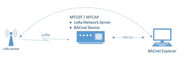
To get data from the LoRa sensor through mPower:
- Verify the device has the BACnet license. BACnet payload management requires a license which is installed on your mPower device when it ships from the factory. If the Payload Management pages are not available, contact your account manager for a license. To add a license, refer to Licensing .
- Verify LoRaWAN Network Settings.
- Go to Network Settings > Network Server.
- Set LoRa Mode to Network Server.
- Set the Channel Plan for your region.
- Make sure the Packer Forwarder and the Network Server are running.
- Go to Key Management.
- Set the Join Server to Local Join Server.
- Configure Local Network Setting.
- Configure Local Network Setting.
- Set up and connect your sensor. These steps depend on the sensor brand and are outside the scope of this document.
- Observe the LoRaWAN > Packets page. If the LoRaWAN network and sensor are configured properly, a Join Request from the sensor appears in the Recent Join Requests pane with the Success result. You will see Packets sent by the sensor in the Packets pane.
- Click Refresh to update the data on the page.
- Go to the LoRaWAN > Devices page. A new entry with the sensor Device EUI has been added to the End Devices and Sessions panes.
- Configure BACnet. For details, refer BACnet Configuration.
- Add sensors through Managed Sensors page.
- Create BACnet Objects.
- Setup a BACnet Explorer to get sensor data via BACnet. These steps depend on which BACnet Explorer you select and are outside the scope of this document.
- Go to Network Settings > Network Server.
Configuring BACnet
To configure the system as a BACnet device:
- Go to Payload Management > BACnet Configuration.
- Check Enabled to enable the BACnet Device.
- Enter a Port value between 1 to 65535. Required.
- Enter a Device Object Identifier value between 1 to 4194302. Required.
- Enter a Device Object Name of up to 64 characters. Required.
- Enter a Device Description of up to 64 charact6ers. Optional.
- Enter APDU Timeout value between 1-65 seconds. Default is 3. Required.
- Enter number of APDU Retries. Range is 1-255. Default is 3. Required.
- Click Submit and then click Save and Apply.
BACnet Objects
BACnet Objects define the data transferred from the sensor to the BACnet explorer.
- Analog input
- Binary input
- Positive integer value
- Integer value
- Character string value
Adding a New BACnet Object through the Web Management Interface
Before adding a BACnet Object, you must add one ore more sensors through the Managed Sensors page.
To add a new BACnet Object:
- Go to Payload Management > BACnet Objects.
- Click the Add Object tab.
- Select a Device EUI from the drop-down list.
- Select a Property from the drop-down list. Required. The Property lists contains properties that correspond to the sensor definition of the selected Device EUI.
- Select a Type from the drop-down list. Required. Type is based on the selected Property.
- Enter an Identifier between 0-4194302. Required. Identifier provides a unique value in mPower for BACnet objects of the same type.
- Enter a Name up to 32 characters. Required.
- Enter a Description up to 32 characters. Optional.
- Click Submit to add a new object and go to the BACnet Objects page. Click Submit and Add New Object to continue adding BACnet Objects for the selected DeviceEUI.
Importing BACnet Objects
mPower allows you to add BACnet objects by importing a valid JSON file.
To import a BACnet Objects list:
- Go to Payload Management > BACnet Objects.
- Click the Folder icon under Choose File and browse to select the file you want to use.
- Click Import.
- Click Save and Apply.
Managed Sensors
Adding Managed Sensors
To add managed sensors through the web interface:
- Go to Payload Management > Managed Sensors.
- Click Add Sensor in the upper right corner.
- Enter the Device EUI in the format XX-XX-XX-XX-XX-XX-XX-XX.
- Select the sensor Manufacturer from the drop-down list.
- Select the sensor type from the Type drop-down list. These options depend on the Manufacturer selected in the previous step.
- Click Finish to add the sensor.
Importing Managed Sensor Information
To import a list of LoRa sensors, sensor information must be in a JSON file in the following format:
[

     {
         "id" : "XX-XX-XX-XX-XX-XX-XX-XX",
         "sensor" : "manufacturer/sensor_model",
         "src" : "lora"
     }

]
Where ID is the sensor Device EUI, sensor includes the manufacturer's name and sensor model type by a slash. The only src is lora, which must be all lowercase.
[

     {
         "id" : "98-34-e5-05-00-00-0e-da",
         "sensor" : "radiobridge/RBS301-WAT",
         "src" : "lora"
     }

]
To import the sensor file:
- Go to Payload Management > Managed Sensors.
- Click the Folder icon under Choose File and browse to select the file you want to use.
- Click Import.
- Click Save and Apply.
Viewing Sensor Details
To view sensor details:
- Go to Payload Management > Managed Sensors.
- Click the View Details (eye) icon for the sensor..
mPower opens a Sensor Details window showing DeviceEUI, source, manufacturer/sensor type and any BACnet Objects for that sensor. The window includes a link for adding new BACnet objects. For more information, refer to BACnet Objects.
Deleting a Sensor
To delete a sensor:
- Go to Payload Management > Managed Sensors.
- Click the Remove (trashcan) icon for the sensor.
- Confirm the deletion.
Deleting All
To delete all the sensors:
- Go to Payload Management > Managed Sensors.
- Click Delete All.
- Confirm the deletion.
Downloading the Managed Sensor List
To download a JSON file with sensor details:
- Go to Payload Management > Managed Sensors.
- Click the Download.
Sensor Definitions
Sensor definitions are a sensor definition JSON file and a corresponding sensor decoder file.
By default mPower includes pre-defined sensor definitions for MultiTech's Radio Bridge, Adeunis, and Elsys sensors. These appear on the Sensor Definitions tab and Default tab. The Sensor Definitions tab also lists any custom sensor definitions that have been imported into mPower. For just a list of custom definitions, go to the Custom tab.
Viewing Sensor Definition Details
To view sensor details:
- Go to Payload Management > Sensor Definitions.
- Click the View Details (eye) icon for the sensor definition.
mPower opens a Sensor Details window showing the properties, type, an units for that sensor definition.
Filtering and Sorting the Sensor Definition Lists
- Enter filter term in the Filter By field.
- Click on a column heading.
Importing Custom Sensor Definitions
When importing customer sensor definitions, you must upload both a sensor definition JSON file describing the sensor data structure and a corresponding sensor decoder that declares the decode Uplink function.The sensor definition file for importing definitions must be JSON format that has three sections: description (optional), properties (required), and decoder (required).
Example Sensor Definition JSON File Structure
{


    "description" : "Optional description goes here",


    "properties" : {

         "DeviceID"             : {"type" :"string", "size" : 16},
         "DeviceStatus"         : {"type" : "uint8"},
         "BatteryVoltage"       : {"type" : "uint16", "units" : "amp"},
         "CounterA"             : {"type" : "uint16"},
         "CounterB"             : {"type" : "uint16"},
         "SensorStatus"         : {"type" : "uint8"},
         "TotalCounterA"        : {"type" : "uint16"},
         "TotalCounterB"        : {"type" : "uint16"},
         "PayloadCounter"       : {"type" : "uint8"}
    },


    "decoder": "SampleDecoder.js"


  }
Sensor Decoder
The Sensor decoder file is a snippet of JavaScript code that defines the “decodeUplink” function. The JavaScript decodeUplink() function is called when a data uplink message is received from a sensor. This function decodes the binary payload received from the sensor to a human-readable JSON object that gets sent upstream to the BACnet Server.
For a Sample Decoder refer to: Decoder Sample.
To import custom sensor files:
- Go to Payload Management > Sensor Definitions and click on the Import tab.
- Enter the sensor Manufacturer name up to 15 characters. Must start with a letter and may only contain alphanumeric characters, hyphens, and underscores. It is case sensitive. Required.
- If uploading a variation of an existing sensor type, check Allow Overwrite so mPower uses the new definition for that sensor type.
- Enter a part number or model version for the sensor up to 32 characters. Must start with a letter and may only contain alphanumeric characters, hyphens, and underscores. It is case sensitive. Required.
- Click the Folder icon under Sensor Definition and browse to select the file you want to use.
- Click the Folder icon under Sensor Decoder and browse to select the file you want to use. Note that mPower does not validate the decoder file.
- Click Import.
- Click Save and Apply.
Deleting a Custom Sensor Definition
- Go to Payload Management > Sensor Definitions. To narrow the list to just custom definitions, click the Custom tab.
- Find the sensor definition you want to delete. Click the Remove (trashcan) icon for that sensor definition.
- Confirm the deletion.
Deleting All Custom Sensor Definitions
- Go to Payload Management > Sensor Definitions. To narrow the list to just custom definitions, click the Custom tab.
- Click Delete All.
- Confirm the deletion.
Decoder Sample
This is a sample of a Sensor Definition Decoder file for reference.
SampleDecoder.js file content:
///////////////////////////////////////////////////////////////////////////////////
//                         Prototypes
///////////////////////////////////////////////////////////////////////////////////
Uint8Array.prototype.readUInt16BE = function (offset) {
    var dataView = new DataView(this.buffer);
    return dataView.getUint16(offset);
};
Uint8Array.prototype.readInt16BE = function (offset) {
    var dataView = new DataView(this.buffer);
    return dataView.getInt16(offset);
};
Uint8Array.prototype.readUInt8 = function (offset) {
    var dataView = new DataView(this.buffer);
    return dataView.getUint8(offset);
};
Uint8Array.prototype.readUInt32BE = function (offset) {
    var dataView = new DataView(this.buffer);
    return dataView.getUint32(offset);
};


///////////////////////////////////////////////////////////////////////////////////
//                         Helper functions
///////////////////////////////////////////////////////////////////////////////////
function bcd(dec) {
return ((dec / 10) << 4) + (dec % 10);
}

function unbcd(bcd) {
return ((bcd >> 4) * 10) + bcd % 16;
}

function toHEXString(payload, index, length){
    var HEXString = '';
    for(var i = 0; i < length; i++){
        if(payload[index + i] < 16){
            HEXString = HEXString + '0';
        }
        HEXString = HEXString + payload[index + i].toString(16);
    }
    return HEXString;
}

function readInt16BE(payload, index){
    var int16 = (payload[index] << 8) + payload[++index];
    if(int16 & 0x8000){
        int16 = - (0x10000 - int16);
    }
    return int16;
}

function readUInt16BE(payload, index){
    return (payload[index] << 8) + payload[++index];
}

function readInt8(payload, index){
    var int8 = payload[index];
    if(int8 & 0x80){
        int8 = - (0x100 - int8);
    }
    return int8;
}

////////////////////////////////////////////////////////////////////////////////////////////////
// decodeUplink: Take received byte array and add custom
// code to define specific byte paramaeters
//
//   Input:
//    port = manufacturer specific, use if specified, else ignore
//    byteArray = sesnor data post base64 decode, byte array of payload values
//
//
//     Sensor payload as HEX: 02060004A30B00EDB9EF000101000000000000040004B0
//
//     Incoming payload (byteArray):
//             [ 02,06,00,04,A3,0B,00,ED,B9,EF,00,01,01,00,00,00,00,00,00,04,00,04,B0 ]
//
//     { received_at: '2022-09-08T14:40:31.418Z',
//       payload_type: 2,
//       payload_variant: 6,
//       device_id: '0004a30b00edb9ef',
//       device_status: 0,
//       battery_voltage: 2.57,
//       counter_a: 0,
//       counter_b: 0,
//       sensor_status: 0,
//       total_counter_a: 4,
//       total_counter_b: 4,
//       payload_counter: 176 }
//
//   WARNING:  PLEASE ONLY USE PRIMITIVE CLASSES!!!! Dervived classes NOT supported
//
//    function DecoderTest() {
//      var bytes = new Uint8Array([0x02, 0x06, 0x00, 0x04, 0xA3, 0x0B, 0x00, 0xed, 0xb9,
//             0xef, 0x00, 0x01, 0x00, 0x00, 0x00, 0x00, 0x00, 0x04, 0x00, 0x04, 0xb0]);
//      return decodeUplink(1, bytes);
//  }
//
////////////////////////////////////////////////////////////////////////////////////////////////
function decodeUplink(port, byteArray) {
    var d = {};
    var payload = byteArray;

    d.payloadType = payload[0];
    d.payloadVariant = payload[1];
    d['DeviceID'] = toHEXString(payload, 2, 8)

    switch(d.payloadVariant){
        case 0x06:
            d['DeviceStatus'] = payload[payload.length - 13];
            d['BatteryVoltage'] = readUInt16BE(payload, payload.length - 12) / 100;
            d['CounterA'] = readUInt16BE(payload, payload.length - 10);
            d['CounterB'] = readUInt16BE(payload, payload.length - 8);
            d['SensorStatus'] = payload[payload.length - 6];
            d['TotalCounterA'] = readUInt16BE(payload, payload.length - 5);
            d['TotalCounterB'] = readUInt16BE(payload, payload.length - 3);
            d['Payloadcounter'] = payload[payload.length - 1];
            break;
        case 0x07:
            d['SensorStatus'] = payload[payload.length - 5];
            d['TotalCounterA'] = readUInt16BE(payload, payload.length - 4);
            d['TotalCounterB'] = readUInt16BE(payload, payload.length - 2);
            break;
        case 0x08:
            d['DeviceStatus'] = payload[payload.length - 4];
            d['BatteryVoltage'] = readUInt16BE(payload, payload.length - 3) / 100;
            d['SensorStatus'] = payload[payload.length - 1];
            break;
    }

    // return the decoded payload as an object or return an empty object
    return d;

}

// Uncomment below to test

//    function DecoderTest() {
//      var bytes = new Uint8Array([0x02, 0x06, 0x00, 0x04, 0xA3, 0x0B, 0x00, 0xed, 0xb9,
//             0xef, 0x00, 0x01, 0x00, 0x00, 0x00, 0x00, 0x00, 0x04, 0x00, 0x04, 0xb0]);
//      return decodeUplink(1, bytes);
//  }

//  print( DecoderTest() );
Setup
Global DNS
The Global DNS Configuration page allows the user to set user-defined DNS servers. User-defined DNS servers in this page are always used to resolve hostnames regardless of what the WAN settings are and what WAN interface is being used. If the Global DNS primary and secondary servers are not configured here, the DNS servers used default to the servers configured for the current WAN.
Here are the key configuration scenarios for both Global DNS and forwarding server and their results (the device refers to a MultiTech device):
- If you do not configure Global DNS and enable forwarding, the device acts as a proxy server for any devices on the LAN network(s). In this mode, the device uses WAN DNS settings. Client settings: On the client, you must configure the device as the default gateway and DNS server. The easiest way to accomplish this is by using the DHCP server on the device.
- If you configure Global DNS and enable forwarding, DNS requests are forwarded to servers configured in the Global DNS settings. The device still acts as a proxy. Client settings: Clients must be configured the same as in the previous case above.
- If you configure Global DNS and disable forwarding, the default gateway and DHCP server on clients should point to the device and the DNS servers on the client must use the same DNS as the Global DNS settings. Client settings: The client device uses the device as default gateway and the DHCP server, but must have DNS servers configured to what options you plan to use.
- If neither item is configured/enabled, make sure to configure your device properly to forward DNS.
To configure Global DNS:
- Click Setup > Global DNS.
- Under Global DNS Configuration, leave Enable Forwarding Server unchecked. (If you check this, the forwarding server is active and global DNS is not configured).
- To set global DNS servers, enter IP addresses for the both Primary and Secondary Servers. (These servers override any DNS servers specified elsewhere in the UI. If none are entered, the system defaults to servers configured for the current WAN.)
Hostname Configuration
Hostname allows the user to change the hostname of the device to distinguish the device from other devices on the network.
To modify the default hostname:
- Under Hostname Configuration, enter the Hostname for your device.
- Click Save and Apply to save your changes OR click Reset to Default to return to default settings.
WAN Setup
Configuring WAN Failover Priority
Failover mode regulates which WAN is used for the Internet connection and switches the WAN if a connectivity failure is detected.
Failover mode enables the WAN with the highest priority as displayed on the WAN Configuration page. If the WAN with priority 1 is disabled or a connection failure is detected, the WAN with priority 2 is automatically selected for establishing connection to the Internet.
Ethernet (eth0) is priority 1 by default.
If Ethernet is used as WAN, the DHCP server must be disabled.
- Click Setup > WAN Configuration.
- Under Options, click the up and down arrows to change the priority of the appropriate WAN.
- Click Save and Apply to save the change.
For field descriptions see Failover Configuration Fields
For information on editing WAN Failover see Editing Failover Configuration
Editing Failover Configuration
The device can use the active or passive mode to monitor the Internet availability in WAN. The default condition is active mode.
Active mode can be type ICMP (ping) or TCP. ICMP periodically pings the designated host at the specified interval. TCP tries to make a connection to the designated host at the interval specified.
For both ICMP and TCP, if a response is not received, the device switches to the WAN with lower priority. The device continues to ping the designated host at the interval specified for WAN with the higher priority and switches back when the ping is successful. When passive mode is enabled, the device switches the WANs when the network interface is down. The currently active WAN is displayed on the home page under the label WAN Transport.
To edit failover configuration:
- Click Setup > WAN Configuration.
- Under the Options column at the right, click the pencil icon (edit) for the selected WAN. The Failover Configuration page is displayed.
- Make the desired changes. Refer to Failover Configuration Fields for details.
- Click Finish.
- If you are finished making changes, click Save and Apply.
Failover Configuration Fields
| Field | Description |
|---|---|
| Monitoring Mode | Use the drop-down list to select the mode to connect to the host: PASSIVE or ACTIVE. |
| Interval | Enter the number of seconds between each check. Default is 60 seconds. |
| Host Name | Enter the host name or IP address to use for the check. Default is www.google.com. |
| Mode Type | Use the drop-down list to select the mode type: ICMP or TCP. Default is ICMP. (Active Monitoring Mode) |
| TCP Port | Enter the TCP Port number to connect to the host. (Mode TCP) |
| ICMP Port | Enter the number of ICMP pings to be sent to the specified host. Default is 10. (Mode ICMP) |
Configuring IP Address for LAN
Your device manages traffic for your local area network (LAN). To change the IP address and DNS configuration:
Configuring Dynamic Domain Naming System (DDNS)
This feature allows your router to use a DDNS service to associate a hosted server's domain name with a dynamically changing internet address. To configure your router to use DDNS:
- From Setup, select DDNS Configuration.
- In the Configuration group, check Enabled.
-
In the Service drop-down list, select a DDNS service. To define a
service that isn't listed choose Custom.
- For custom DDNS service, in the Service field, type the DDNS server's URL.
- For custom DDNS service, in the Port field, type the DDNS server's port.
- In the Domain field, type the registered Domain name.
- In the Update Interval field, type the days that can pass with no IP Address change. At the end of this interval, the existing IP Address is updated on the server so that the address does not expire. The range of the interval you can enter is between 1 and 99 days. The default is 28 days.
- Check Use Check IP, if you want to query the server to determine the IP address before the DDNS update. The IP address is still assigned by the wireless provider and the DDNS is updated based on the address returned by Check IP Server. If disabled, the DDNS update uses the IP address from the Cellular link. The default is Use Check IP.
- In the Check IP Server field, type the name to which the IP Address change is registered. Example: checkip.dyndns.org
- In the Check IP Port field, type the port number of the Check IP Server. The default is 80.
- Click Submit.
- To save your changes, click Save and Restart.
Entering authentication information
Your DDNS server requires you to identify yourself before you can make changes.
- In the Username field, type the name that can access the DDNS Server. The default is NULL. You receive your name when you register with the DDNS service.
- In the Password field, type the password that can access the DDNS Server. The default is NULL. You receive your password when you register with the DDNS service.
- Click Submit. If you are finished making changes click Save and Apply.
Forcing a DDNS server update
To update the DDNS server with your IP address, click Update.
Configuring Dynamic Host Configuration Protocol (DHCP) Server
To view, add, or edit DHCP servers, see the IPv4 DHCP Servers (IPv4 support) or DHCPv6 and Router Advertisement (for IPv6 support) list under Setup > DHCP Configuration.
You can configure multiple DHCP servers. Only one DHCP server can be created per LAN network interface. You can configure your device to function as a DHCP server that supplies network configuration information, such as IP address, subnet mask, and broadcast address, to devices on the network.
By default, the DHCP server is configured and enabled for Bridge (br0) network interface. If a LAN network interface is NOT under the bridge, DHCP server can be configured and enabled for it..
DHCP Server is disabled automatically if you modify the network interface under Setup > Network Interface including:
- changes to the interface subnet
- adding network interface under the bridge
- changing the interface from LAN to WAN (Ethernet interface only)
- removing all LANs from under the bridge (DHCP for br0 will be disabled in this case)
DHCP Server cannot be enabled if the network interface is under the bridge, or is not enabled or configured properly (for example, when eth0 is configured as WAN, or Wi-Fi Access Point is disabled).
To edit the configuration of an existing IPv4 DHCP server or add a new one:
- Go to Setup > DHCP Configuration. See the IPv4 DHCP Servers list.
- To edit a DHCP Server, click the pencil icon (edit) for the selected interface, OR to add a DHCP Server, click the Add IPv4 DHCP Server button.
- The DHCP Configuration fields appear. To use the DHCP feature, check Enabled.
- In the Interface field, select the network interface. Note: The Interface field is read-only when you edit DHCP Server.
- The Subnet field displays the subnet address.
- The Mask field displays the network's subnet mask.
- In the Gateway field, type the gateway address.
- In the Domain field, type your network domain, if any.
- In the Lease Time field, enter the DHCP lease time. Lease time is set in days, hours, and minutes (dd-hh-mm). A Lease Time of 00-00-00 is an infinite lease time.
- In the Lease Range Start field and in the Lease Range End field, type the range of IP addresses to be assigned by DHCP.
- Click Submit. If you are finished making changes, click Save and Apply.
To edit the configuration of an existing DHCPv6 and Router Advertisement server or add a new one:
- Go to Setup > DHCP Configuration. See the DHCPv6 and Router Advertisement list.
- To edit a DHCP Server, click the pencil icon (edit) for the selected interface, OR to add a DHCP Server, click the Add DHCPv6/RA button.
- The DHCP Configuration fields appear. To use the DHCP feature, check Enabled.
- In the Interface field, select the network interface from the drop-down including eth0 and wlan1. Note: Interface field is read-only when you edit DHCP Server.
- In the Router Advertisement Mode, select from the drop-down the DHCP IPv6 mode including SLAAC or Stateless DHCP.
- In the Lease Time field, type the DHCP lease time. Lease time is set in days, hours, and minutes (dd-hh-mm). A Lease Time of 00-00-00 is an infinite lease time.
- Click Submit. If you are finished making changes, click Save and Apply.
To add fixed addresses for the DCHP server, see Assigning Fixed Addresses.
Assigning Fixed Addresses
To add fixed addresses for the DCHP server make the changes under the Fixed Addresses section on the DCHP Configuration page:
- In the MAC Address field, type the MAC address to which the specified IP address binds.
- In the IP Address field, type the fixed IP address to be assigned.
- Click Add.
- To save your changes, click Save and Apply.
Configuring LLDP
Overview
Link Layer Discovery Protocol (LLDP) is a simple link layer protocol that allows an end device to announce itself to a neighboring switch or router.
It reports itself with a few basic characteristics, so it is easy to determine the exact location of the device. Thus, the benefits are that (switch) outlets can be quickly checked for proper connectivity, which greatly enhances and simplifies deployment and management for users.
The LLDP feature allows the network manager to see on the connected switch which device is connected to which port on the switch, how much power is being requested, what the IP address is, etc. Using this information, they can determine where the Conduit is located and, if necessary, remotely disconnect power to the Conduit in case of a PoE device.
Configuring LLDP
To configure and enable LLDP:
- Go to Setup > LLDP Configuration.
- Check Enabled.
- Enter a System Name and System Description of up to 250 characters. Description is optional.
- Enter a TX Interval between 5-32768 seconds. Default is 30.
- Enter a TX Hold value between 2-10. Default is 4.
- Click Submit.
- To save your changes, click Save and Apply.
- TX Interval, transmit interval, defines the interval between LLDP messages in seconds.
- TX Hold, transmit hold multiplier, helps define the total time used determine the LLDP message Time-to-Live (TTL). TTL is the interval in seconds for which the LLDP message remains valid and is stored in neighboring devices that discover the mPower device.
- Example: If TX interval is 30 seconds and the TX hold is 4. The LLDP message advertised TTL is 120 seconds.
Configuring SNMP
The device offers Simple Network Management Protocol (SNMP) which is used for collecting information from network devices on an IP network.
You also have the option to configure SNMP traps which are alerts sent from SNMP-enabled devices to an SNMP agent or manager typically providing device status or condition information.
You can also access the MIB file which is a management information base. This file is a formal description of a set of network objects managed using the Simple Network Management Protocol (SNMP). The format of the MIB is defined as part of the SNMP. (All other MIBs are extensions of this basic management information base.)
Click Download MIB, to download the MIB file.
To configure SNMP:
- Go to Setup > SNMP Configuration.
- Under SNMP Server Configuration, check Enabled to activate the SNMP server. Click Submit.
- Enter a device Name. Optional. This value is returned as the sysName node from the SNMPv2-MIB MIB module.
- Enter the device's physical Location. Optional. This value is returned as the sysLocation node from the SNMPv2-MIB MIB module.
- Specify Contact details for the device. Optional. This value is returned as the sysContact node from the SNMPv2-MIB MIB module.
- If needed, click Add under Allowed IP Addresses for SNMP v1/v2c.
- Click Add Server Configuration.
- Make sure that Enabled is checked.
- Under Version, select from the drop-down either SNMP v1/v2c or SNMP v3.
- For SNMP v1 and SNMP v2c:
- Enter the Configuration Name for your SNMP configuration.
- Enter Community String which is a read-only string used to authenticate incoming SNMP requests.
- For SNMP v3:
- Enter the Authentication Protocol from the drop-down, including NONE, MD5, or SHA1.
- Enter the Security Name which is a username used to
authenticate incoming SNMP v3 requests. If you selected MD5
or SHA1 for Authentication Protocol:
- Enter the Authentication Password, which is a password used to authenticate incoming SNMPv3 requests.
- Confirm the password.
- Enter the Encryption Protocol for SNMPv3 messages from the
drop-down, including NONE, DES or AES-128. If you
selected DES or AES-128 for Encryption Protocol:
- Enter the Encryption Password.
- Confirm the password.
- Click Submit.
- The SNMP Configuration list displays your recently added SNMP Server Configuration. To edit the configuration, click the pencil icon under Options.
- To delete an existing configuration, click the trash can icon under Options.
- To save your changes, click Save and Apply. Or continue to SNMP Trap Destinations and Add Trap Destinations.
To configure SNMP Traps:
- Go to Setup > SNMP Configuration > SNMP Trap Configuration, check Enabled to enable sending SNMP traps on the device..
- The engine ID displays to the right of Enabled. Modify the engine ID or use the default value.
- Click Submit.
- Click Add Trap Destination.
- Make sure that Enabled box is checked.
- Enter the Destination Name.
- Select from the drop-down the Version of SNMP (SNMP v1/v2c or SNMP v3).
- For SNMP v1 or SNMP v2c
- Enter the Destination IP Address.
- Enter the Community String.
- For SNMPv3:
- Enter the Destination IP Address.
- Enter Security Name.
- Enter the Authentication Protocol from the drop-down,
including NONE, MD5, or SHA1. If you selected
MD5 or SHA1 for Authentication Protocol:
- Enter the Authentication Password, which is a password used to authenticate incoming SNMPv3 requests.
- Confirm the password.
- Enter the Encryption Protocol for SNMPv3 messages from the
drop-down, including NONE, DES, or AES-128. If you
selected DES or AES-128 for Encryption Protocol:
- Enter the Encryption Password.
- Confirm the password.
- Click Submit.
- The SNMP Trap Destination list displays your recently added SNMP Trap Destination. To edit the destination, click the pencil icon under Options.
- To delete an existing destination, click the trash can icon under Options.
- To save your changes, click Save and Apply.
To download the MIB file:
- Click Download MIB in the far right corner of the device display.
- Download/save the file from your browser.
Configuring the Global Positioning System (GPS)
This GPS information applies only to the device models that support GPS.
Some devices have a built-in GPS receiver. If your device has a GPS receiver, the device can forward NMEA (National Marine Electronics Association) sentences from the GPS receiver to another device connected to the device. You can also send the GPS data over the network to a remote computer.
The key areas of GPS configuration include: Server Configuration, Client Configuration and NMEA Configuration along with Current Position information.
Notes:
- All enabled sentences are forwarded periodically using the interval specified in the NMEA Configuration section. Before forwarding, the device adds an ID prefix and ID to each enabled NMEA sentence. If set, the NMEA sentences available are those provided by the built-in receiver which are: GPGGA, GPGSA, GPGSV, GPGLL, GPRMC, GPVTG.
- You can simultaneously enable the TCP Server, and TCP/UDP client.
GPS Server Configuration
To setup the GPS Server Configuration:
- Go to Setup > GPS Configuration > Server Configuration.
- To enable server configuration, check TCP Server.
- In the Port field, type the port number on which the TCP server is listening for connections. The default is 5445. You can use up to five digits. Each digit itself must be between 0 and 9. Numbers above 65,535 are illegal as the port identification fields are 16 bits long in the TCP header.
- Enter Password and confirm Password.
- Click Submit.
- To save your changes, click Save and Apply.
Local Configuration
- Go to Setup > Serial IP Configuration > Serial Port Settings and set the mode to Enabled.
- Go to GPS Configuration > Local Configuration, check Serial Port Dump.
- Submit.
- To save your changes, click Save and Apply.
Sending GPS information to a remote server
The Client Configuration allows the device to connect to a remote server using the IP and port information for uploading GPS data.
- To allow the device to connect, go to Setup > GPS Configuration > Client Configuration.
- Check TCP/UDP Client.
- From the Protocol drop-down list, select the protocol of the client (TCP or UDP).
- In the Remote Host field, type the IP address of the remote host.
- In the Port, field type the port number of the remote host.
- If your remote host requests a password, type that password in the Password field. The password is sent to the server in response.
- Click Submit.
- To save your changes, click Save and Apply.
Configuring NMEA Sentences
To configure the time interval, additional prefix or ID information, and which NMEA sentences that can be sent:
- Go to Setup > GPS Configuration > NMEA Configuration.
- In the Interval field, type the amount of time, in seconds, that passes before the NMEA information is sent. The default is 10 seconds. The range is 1 to 255 seconds.
-
You can further identify the device, also called a remote asset, that is
collecting and sending the GPS information. To do so:
- Add ID: The ID is an unique remote asset identification string. The ID string can be any length up to 20 characters. The & and $ are invalid characters. The ID must follow the standard NMEA sentence structure.
- To add more information to the beginning of the ID, in the Add ID Prefix field, type the information.
- Select which NMEA Sentence types you want to send. Select any combination of these options: GGA, GSA, GSV, GLL, RMC, and VTG.
- Click Submit.
- To save changes, click Save and Apply.
SMTP Settings
The following table lists the configuration fields in the SMTP window.
| Field | Description |
|---|---|
| SMTP Configuration | |
| Enabled | Click to use the SMTP feature. |
| Server | Enter the SMTP server address. |
| Port | Enter the port number that the SMTP server uses. |
| Enter the sender email address. This address will be added as the sender email address to the sent emails. | |
| Username | Enter the name that can access the SMTP server. |
| Password | Enter the password that can access the SMTP server. |
| Mail Log Settings | |
| Entries to Keep | Enter the desired number of mail log entries that are to be stored in the device. The range of values is 10 to 1000. If you click Submit, this setting is not applied to the emails that are in progress or deferred. Note that logs are not saved on the device. Also, logs do not persist through power cycles. |
| Send a Test Email | |
| Address | To make sure that the SMTP is configured properly, enter a destination email address, then click Send Test Email. |
Configuring the Serial Port in Serial IP Mode
This feature requires installation and configuration of mCard Accessory Card (such as an MTAC-MFSER) into your device first. To configure the serial terminal connected to the RS-232 connector on your accessory card:
*Note on Modbus RTU/TCP Gateway: This feature was developed for a specific application/use case where a Modbus RTU slave is connected to the Serial Port and a remote Modbus TCP Master. The Modbus Gateway application works as a translator between Modbus RTU (slave) and Modbus-TCP (master) devices.Without Modbus Gateway enabled, the Serial-IP feature simply passes raw data between the serial DB9 interface and the socket representing the TCP connection in the system to a configured remote device. When the Modbus Gateway is enabled, its application runs in the system. The application works as a translator converting between the Modbus-TCP and Modbus RTU protocols. The Modbus Gateway passes data between an RTU connected to the serial port and a Modbus TCP remote client/server. The Modbus Gateway and the Serial-IP features cannot work simultaneously.
Configuring Device to Act as Client for Serial IP
You can set up the device to act as a client.
The TCP, UDP, SSL/TLS client feature enables the device to act as a proxy TCP, UDP, or SSL/TLS client to the serial terminal connected to the RS-232 port on the device. This helps the serial terminal access any TCP, UDP, or SSL/TLS server on the LAN/WAN allowing two-way traffic between the serial device and the remote server.
To use this function, make sure you set a valid Mode under Serial-IP Configuration (i.e. Mode is not Disabled). To configure the IP Pipe in TCP, UDP, SSL/TLS server mode:
- Go to Setup > Serial-IP Configuration > Serial Port Settings > IP Pipe group.
- From the Mode drop-down list, select CLIENT.
- From the Protocol drop-down list, select the desired protocol: TCP, UDP, or SSL/TLS.
- In the Server IP Address field, enter the address of the far-end TCP, UDP, or SSL/TLS server.
- In the Server Port field, enter the port value used by the far-end TCP, UDP, or SSL/TLS server.
- If the primary server is unavailable, in the Secondary IP Address field, enter the address of the alternate TCP, UDP, or SSL/TLS server.
- If the primary server is unavailable, in the Secondary Port field, enter port number value of the alternate TCP, UDP, or SSL/TLS server.
-
From the Connection Activation drop-down list, select a connection
method. Options are:
- ALWAYS-ON.
- DTR-ASSERT. When the DTR signal is asserted, the connection is established.
- CR. Three carriage returns must be received before the TCP, UDP, or SSL/TLS connection is established to the remote server.
- ON-DEMAND. Set the connection as available on-demand.
-
From the Connection Termination drop-down list, select a disconnect
method for the IP pipe. Options are:
- ALWAYS-ON.
- TIMEOUT. The IP pipe connection disconnects if the configured timer expires with no data sent or received. In the Timeout field, enter the desired number of seconds for this timeout. The valid timeout range is from 0 to 900 seconds. Timeout of zero seconds disables the timeout and it is equivalent to ALWAYS-ON.
- SEQUENCE. A sequence of received characters disconnects the IP pipe.
- DTR-TOGGLE. When the DTR control signal is toggled, the IP pipe disconnects.
- In the Buffer Timeout field, enter the timeout after which data is sent to the network if the buffer is not full (in milliseconds).
- In the Buffer Size field, enter the size of the buffer for reading data from the serial port and sending to the network (in bytes). Data is sent when the buffer is full.
- Click Submit.
- To save your changes, click Save and Apply.
To configure security settings:
- Make sure you select SSL/TLS under Protocol.
- Under Security Settings, click the Show to the right.
- Select any TLS version. Check TLSv1.3, TLSv1.2 and/or TLSv1.1 (deprecated). Default: TLSv1.3 and TLSv1.2 are enabled.
- Check any preferred Cipher Suite from the following list: TLS_AES_256_GCM_SHA384, TLS_CHACHA20_POLY1305_SHA256, TLS_AES_128_GCM_SHA256, ECDHE-RSA-AES256-GCM-SHA384, ECDHE-RSA-AES128-GCM-SHA256,TLS_AES_128_GCM_SHA256, and also including the following deprecated ciphers: ECDHE-RSA-AES256-GCM-SHA384, ECDHE-RSA-AES256-SHA, DHE-RSA-AES256-GCM-SHA384, AES256-SHA, ECDHE-RSA-AES128-GCM-SHA256, ECDHE-RSA-AES128-SHA, DHE-RSA-AES128-GCM-SHA256, DHE-RSA-AES128-SHA, and/or AES128-SHA. Default: All. (You can also set the priority order of the ciphers).
- Click Submit.
- To save your settings, click Save and Apply.
Configuring Device to Act as Server for Serial IP
You can set up the device to act as a server.
The TCP, UDP, SSL/TLS server feature enables a TCP, UDP, SSL/TLS client on the Ethernet network to connect to the remote serial terminal that is connected to the RS-232 port on the device. The device acts as a TCP, UDP, SSL/TLS server which allows two-way traffic between the TCP, UDP, SSL/TLS client and the remote terminal on the serial port.
To use this function, make sure you set a valid Mode under Serial-IP Configuration (i.e. Mode is not Disabled). To configure the IP Pipe in TCP, UDP, SSL/TLS server mode:
To configure security settings:
- Make sure you select SSL/TLS under Protocol.
- Under Security Settings, click the Show to the right.
- Select any TLS version. Check TLSv1.3, TLSv1.2 and/or TLSv1.1 (deprecated). Default: TLSv1.3 and TLSv1.2 are enabled.
- Check any Cipher Suite from the following list: TLS_AES_256_GCM_SHA384, TLS_CHACHA20_POLY1305_SHA256, TLS_AES_128_GCM_SHA256, ECDHE-RSA-AES256-GCM-SHA384, ECDHE-RSA-AES128-GCM-SHA256,TLS_AES_128_GCM_SHA256, and also including the following deprecated ciphers: ECDHE-RSA-AES256-GCM-SHA384, ECDHE-RSA-AES256-SHA, DHE-RSA-AES256-GCM-SHA384, AES256-SHA, ECDHE-RSA-AES128-GCM-SHA256, ECDHE-RSA-AES128-SHA, DHE-RSA-AES128-GCM-SHA256, DHE-RSA-AES128-SHA, and/or AES128-SHA. Default: All.
- Click Submit.
- To save your settings, click Save and Apply.
Time Configuration
You can configure how your device manages the setting of time on its domain of systems. As a default, the date and time corresponds to the operating system regional settings. But you can change this configuration. Set the date and time manually or configure the device to get this information from an SNTP server or from the cellular network.
Setting the Date and Time
To set the device's date and time:
Configuring SNTP Client to Update Date and Time
To configure the server from which the SNTP date and time information is taken, and how often:
- To enable SNTP to update the date and time, check Enabled.
- In the Polling Time field, type the time that passes (in minutes), after which the SNTP client requests the server to update the time. Default is 120 minutes.
- In the Server field, type the SNTP server name or IP address that is contacted to update the time.
- In the Backup Server 1 - 4 fields, you may enter the SNTP server name or IP address of up to four backup SNTP servers. These fields are optional.
- Click Submit.
- To save your changes, click Save and Apply.
Cellular Time
This feature allows you to configure the device to update the date and time from the cellular network and specify how often to do so.
To use cellular network to update the date and time:
.- For Cellular Time, select Enabled.
- In the Polling Time field, type the time that passes, after which the device requests to update the time from the cellular network. The range is 5-1440 minutes. Default is 120 minutes. You must enter time in minutes.
- Click Submit.
- To save your changes, click Save and Apply.
Wireless
Wi-Fi Access Point
If you ordered a device with Wi-Fi capability, it can be configured as a wireless access point (AP). This allows Wi-Fi enabled devices to connect to your device using Wi-Fi. The Wi-Fi access point can have up to 5 clients at a time. To set up your device as an access point:
- Go to Wireless > Wi-Fi Access Point.
- To enable Wi-Fi Access Point mode, select Enabled.
- To set the SSID (service set identifier) for the access point supported by your device, in the SSID field, type the name. The Wi-Fi devices look for this ID in order to join the wireless network. All wireless devices on a WLAN must use the same SSID in order to communicate with the access point.
- To specify the data rates supported, in the Network Mode drop-down list, select the desired option. Possible values are B/G/N-Mixed, B/G-Mixed, B-Only, and N-Only.
- From the Channel drop-down list, select the channel on which the device operates. Channels 1-11 are available.
- In the Beacon Interval field, enter the period of time, in milliseconds, when the access point sends a beacon packet. Beacons help synchronize a wireless network. For most applications, the default value of 100 provides good performance.
- In the DTIM Interval field, enter how often a beacon frame includes a Delivery Traffic Indication Message, and this number is included in each beacon frame. It is generated within the periodic beacon at a frequency specified by the DTIM Interval. A delivery traffic indication message is a kind of traffic indication message (TIM) which informs the clients about the presence of buffered multicast/broadcast data on the access point. The default value of 1 provides good performance for most applications. You might want to increase this value when using battery powered Wi-Fi devices, which can sleep (at reduced power consumption) during the longer DTIM interval period. You must balance the power savings from increasing the DTIM interval against possible reduced communication throughput.
- In the RTS Threshold field, type the frame size at which the AP transmissions must use the RTS/CTS protocol. This is often used to solve hidden node problems. Using a small value causes RTS packets to be sent more often, consuming more of the available bandwidth. However, the more RTS packets that are sent, the quicker the system can recover from interference or collisions.
Setting Security Options
Specify the security protocol that your device uses to secure the communications from the device to the connected devices under Security Options.
-
From the Mode drop-down list, select the security protocol you want to
use. Options include:
- None
- WPA-PSK: Use Wi-Fi protected access to secure data exchanged on your network.
- WPA2-PSK: Use Wi-Fi protected access version 2 to secure data exchanged on your network.
- WPA/WPA2-PSK: Use Wi-Fi protected access version 1 and 2 to secure data exchanged on your network.
-
To select WPA-PSK, WPA2-PSK or WPA-PSK/WPA2-PSK modes:
- Select the WPA Algorithm from the drop-down list. Choose from TKIP, AES or TKIP+AES.
- In the Shared Key field, type the key that is used for encrypting and decrypting the data.
- To remove the mask characters, thereby making the Shared Key visible, check Unmask.
- When done, click Submit.
- To save your changes, click Save and Apply.
Viewing Information About Wi-Fi Clients Using Your Wireless Network
To view information about clients (such as computers, tablets, and smart phones) that are connected to your device's Wi-Fi access point:
- The Clients group displays a list of clients using your device's Wi-Fi.
- To update the list, click Refresh.
Wi-Fi as WAN
Setting up Bluetooth
The Bluetooth-IP feature allows a data connection between a remote TCP/UDP client or server and a local Bluetooth device. To set up the Bluetooth connection:
IP Pipe in TCP/UDP Server mode
To configure the IP Pipe in TCP/UDP Client mode
- In the IP Pipe group, from the Mode drop down list, select CLIENT.
- From the Protocol drop-down list, select the desired protocol, either TCP or UDP.
- In the Server IP Address field, type the address of the far-end TCP-UDP server.
- In the Server Port field, type the port value used by the far-end TCP/UDP Server.
- In case the primary server is unavailable, in the Secondary IP Address field and in the Secondary Port field, type the IP address and port number, respectively, of the alternate TCP/UDP server.
- From the Connection Activation drop-down list, select a connection
method. Options are:
- ALWAYS-ON
- ON-DEMAND
- CR: Three carriage returns must be received from the Bluetooth side before TCP/UDP connection is established to the remote server.
- From the Connection Termination drop-down list select a disconnect
method for the IP pipe. Options are:
- ALWAYS-ON:
- TIMEOUT: The IP pipe connection disconnects if the configured timer expires with no data sent or received. A timeout of zero seconds disables the timeout, it is equivalent to ALWAYS-ON.
- SEQUENCE: A sequence of characters received from the Bluetooth side used to disconnect the IP pipe.
- Click Submit.
- To save your changes, click Save and Apply.
- The device immediately connects to the local Bluetooth device. If successful the Status field displays Connected. If IP Pipe is configured for SERVER, the IP connection is initiated by the far-end TCP/UDP client.
- If Mode is set to CLIENT, the device initiates connections for the far-end TCP/UDP server based on the configured Connection Activation conditions are met.
To configure security settings:
- Make sure you select SSL/TLS under Protocol.
- Under Security Settings, click the Show to the right.
- Select any TLS version. Check TLSv1.3, TLSv1.2 and/or TLSv1.1 (deprecated). Default: TLSv1.3 and TLSv1.2 are enabled.
- Check any preferred Cipher Suite from the following list: TLS_AES_256_GCM_SHA384, TLS_CHACHA20_POLY1305_SHA256, TLS_AES_128_GCM_SHA256, ECDHE-RSA-AES256-GCM-SHA384, ECDHE-RSA-AES128-GCM-SHA256,TLS_AES_128_GCM_SHA256, and also including the following deprecated ciphers: ECDHE-RSA-AES256-GCM-SHA384, ECDHE-RSA-AES256-SHA, DHE-RSA-AES256-GCM-SHA384, AES256-SHA, ECDHE-RSA-AES128-GCM-SHA256, ECDHE-RSA-AES128-SHA, DHE-RSA-AES128-GCM-SHA256, DHE-RSA-AES128-SHA, and/or AES128-SHA. Default: All.
- Click Submit.
- To save your settings, click Save and Apply.
Bluetooth Low Energy (BLE)
Bluetooth Low Energy allows you to search and/or scan for BLE devices. You can connect with selected BLE device to obtain the list of UUIDs for services and characteristics that are supported on the device.
A python library called gattlib is integrated into the device and can be used for scans, reads, writes, and handling notifications.
You must develop a custom application to read and accept the data from a BLE device. Please refer to the example on the BLE for mLinux page as well as the Creating a Custom Application page.
- Go to Wireless > Bluetooth Low Energy > Settings, check the Enabled box.
- Under Power Mode, select from the drop-down including Custom, High, Medium or Low.
- Click Submit.
- Under the Available Device Servers, the detected BLE devices appear.
- To choose a device from the Available Device Servers, click on the name of your desired device.
- If you do not see your desired device, click Add Device. Enter the Name and MAC Address of your BLE device.
- Click OK. Your device appears under Saved Devices.
- Click Save and Restart to save your changes.
You may also restart BLE by clicking Reset Bluetooth above Saved Devices section.
Firewall
Normal Firewall Settings
The device's firewall enforces a set of rules that determine how incoming and outgoing packets are handled. By default, all outbound traffic originating from the LAN is allowed to pass through the firewall, and all inbound traffic originating from external networks is dropped. This effectively creates a protective barrier between the LAN and all other networks.
Go to Firewall > Settings to see the current firewall configuration. The firewall's Normal Settings mode (default) lets you manipulate and add DNAT, SNAT, and Filter rules directly. DNAT rules can manipulate the destination address and port of a packet; similarly SNAT rules can manipulate the source address and port of a packet. We recommend using these normal settings. Filter rules apply an ACCEPT, REJECT, DROP, or LOG action to a packet. DNAT, SNAT, and Filter rules can be associated if they are named the same.
The firewall is built on top of iptables. The different rule groups correspond to their respective chains in iptables.
Note: As a best security practice, the device employs minimum firewall rules by default. This means by default the device allows all outbound traffic from it in the Output Filter Rules. (Traffic through the device is handled by the Port Forwarding Rules.) But all traffic to the device via WAN interfaces is blocked by default in the Input Filter Rules. Users may create their own specific and targeted input filter rules to allow certain traffic to the device based on their specific needs.
Prerouting Rule
Add a DNAT rule
To add prerouting or DNAT rule to your firewall:
- Go to Firewall > Settings to display the Firewall window.
- In the Prerouting Rules group, click Add DNAT Rule.
- In the Filter Rule section, enter a name for the rule and optionally, a description.
- In the Destination IP field, enter the destination IP address that applies to this rule.
- In the Destination Port field, enter the destination port that applies to this rule. If there is a range of ports, the ending port is automatically set.
- In the Destination Mask field, enter the subnet mask of the destination that applies to this rule.
- In the Destination Interface field, select the interface used by the destination that applies to this rule from the drop-down menu. Select from ANY, LAN, WAN, ETHERNET, CELLULAR, WI-FI WAN, WI-FI AP, or OPENVPN.
- In the Source IP field, enter the source IP address that applies to this rule.
- In the Source Port field, enter the source port that applies to this rule.
- In the SourceMask field, enter source subnet mask that applies to this rule.
- In the SourceMAC field, enter the source MAC address for the device that applies to this rule.
- In the SourceInterface field, select the source interface that applies to this rule from the drop-down menu. Select from ANY, LAN, WAN, ETHERNET, CELLULAR, WI-FI WAN, WI-FI AP, or OPENVPN.
- In the Protocol drop-down list, select the protocol of the messages that apply to this rule. Select from TCP/UDP, TCP, UDP, or ANY.
- In the NAT IP field, enter the local IP address for the Network Address Translation.
- In the NAT Port field, enter the port used for the Network Address Translation.
- Check Enable NAT Loopback if you want to redirect LAN packets destined for the WAN's public IP address.
- Click Submit.
- To save your changes, click Save and Apply.
Input Filter Rules
To add an input filter rule to your firewall:
- Go to Firewall > Settings to display the Firewall window.
- In the Input Filter Rules group, click Add Rule.
- In the Filter Rule section, enter a name for the rule and optionally, a description.
- In the Destination IP field, enter the destination IP address that applies to this rule.
- In the Destination Port field, enter the destination port that applies to this rule. If there is a range of ports, the ending port is automatically set.
- In the Destination Mask field, enter the subnet mask of the destination that applies to this rule.
- In the Destination Interface field, select the interface used by the destination that applies to this rule from the drop-down menu. Select from ANY, LAN, WAN, ETHERNET, CELLULAR, WI-FI WAN, WI-FI AP, or OPENVPN.
- In the Source IP field, enter the source IP address that applies to this rule.
- In the Source Ports field, enter the source port range that applies to this rule.
- In the Source Mask field, enter source subnet mask that applies to this rule.
- In the Source MAC field, enter the source MAC address for the device that applies to this rule.
- In the Source Interface field, select the source interface that applies to this rule from the drop-down menu. Select from ANY, LAN, WAN, ETHERNET, CELLULAR, WI-FI WAN, WI-FI AP, or OPENVPN.
- In the Protocol drop-down list, select the protocol of the messages that apply to this rule. Select from TCP/UDP, TCP, UDP, or ANY.
- In the Chain field, select the grouping based on the type of traffic affected by the rule from the drop-down menu. Select from INPUT, FORWARD, or OUTPUT.
- In the Target field, select the desired action of the firewall based on this rule from the drop-down menu. Choose from ACCEPT, REJECT, DROP, or LOG.
- Click Submit.
- To save your changes, click Save and Apply.
Forward Filter Rules
This page defines rules for forward filtering of connections and data.
- Go to Firewall > Settings to display the Firewall window.
- Click Add Rule in the Forward Filter Rules section.
- Enter a name for the rule and optionally, a description.
- In the Destination IP field, type the IP address of the device or network that packets are to be sent to. Type ANY if the destination address does not matter.
- In the Destination Port field, type the port packets are destined for. Common destination ports are listed in the Destination Port field's attached drop-down list. Type ANY if the destination port does not matter.
- In the Destination Mask field, type the network mask of the destination network.
- In the Destination Interface field, select the interface used by the destination that applies to this rule from the drop-down menu. Select from ANY, LAN, WAN, ETHERNET, CELLULAR, WI-FI WAN, WI-FI AP, or OPENVPN.
- In the Source IP field, type the IP address of the device or network that the traffic originates from. Type ANY if the source address does not matter.
- In the Source Port field, type the port that is the origin of the traffic. Type ANY if the source port does not matter.
- In the Source Mask field, type a network mask for the origin of the traffic.
- In the Source MAC field, enter the source MAC address for the device that applies to this rule.
- In the Source Interface field, select the source interface that applies to this rule from the drop-down menu. Select from ANY, LAN, WAN, ETHERNET, CELLULAR, WI-FI WAN, WI-FI AP, or OPENVPN.
- In the Protocol drop-down list, select the protocol of the messages that apply to this rule. Select from TCP/UDP, TCP, UDP, or ANY.
- In the Chain field, this parameter is the grouping based on the type of traffic affected by the rule from the drop-down menu. Keep this field as FORWARD.
- In the Target field, select the desired action of the firewall based on this rule from the drop-down menu. Choose from ACCEPT, REJECT, DROP, or LOG.
- Click Submit.
- To save your changes, click Save and Apply.
Output Filter Rules
To prevent a device within the LAN from communicating with a device in an external network, you must establish a firewall rule to drop packets destined to the external device.
- Go to Firewall > Settings to display the Firewall window.
- Click Add Rule in the Output Filter Rules section.
- Enter a Name for the rule and optionally, a Description.
- In the Destination IP field, type the IP address of the device or network that packets are to be sent to. Type ANY if the destination address does not matter.
- In the Destination Port field, type the port for which that the packets are destined. Common destination ports are listed in the Destination Port field's attached drop-down. Type ANY if the destination port does not matter.
- In the Destination Mask field, type the network mask of the destination network.
- In the Destination Interface field, select the interface used by the destination that applies to this rule from the drop-down. Select from ANY, LAN, WAN, ETHERNET, CELLULAR, WI-FI WAN, WI-FI AP, or OPENVPN.
- In the Source IP field, type the IP address of the device or network that the traffic originates from. Type ANY if the source address does not matter.
- In the Source Port field, type the port that is the origin of the traffic. Type ANY if the source port does not matter.
- In the Source Mask field, type a network mask for the origin of the traffic.
- In the SourceMAC field, enter the source MAC address for the device that applies to this rule.
- In the Source Interface field, select the source interface that applies to this rule from the drop-down. Select from ANY, LAN, WAN, ETHERNET, CELLULAR, WI-FI WAN, WI-FI AP, or OPENVPN.
- From the Protocol drop-down, select the protocol of the messages that apply to this rule. Choose from TCP/UDP, TCP, UDP, or ANY.
- In the Chain field, select the grouping based on the type of traffic affected by the rule from the drop-down. Select from INPUT, FORWARD, or OUTPUT.
- In the Target field, select the desired action of the firewall based on this rule from the drop-down. Choose from ACCEPT, REJECT, DROP, or LOG.
- Click Submit.
- To save your changes, click Save and Apply.
Postrouting Rule
Add a SNAT rule
To add postrouting or SNAT rule to your firewall:
- Go to Firewall > Settings to display the Firewall window.
- In the Postrouting Rules group, click Add SNAT Rule.
- In the Postrouting Rule section, enter a name for the rule and optionally, a description.
- In the Destination IP field, enter the destination IP address that applies to this rule.
- In the Destination Port field, enter the destination port that applies to this rule. If there is a range of ports, the ending port is automatically set.
- In the Destination Mask field, enter the subnet mask of the destination that applies to this rule.
- In the Destination Interface field, select the interface used by the destination that applies to this rule from the drop-down menu. Select from ANY, LAN, WAN, ETHERNET, CELLULAR, WI-FI WAN, WI-FI AP, or OPENVPN.
- In the Source IP field, enter the source IP address that applies to this rule.
- In the Source Port field, enter the source port that applies to this rule.
- In the SourceMask field, enter source subnet mask that applies to this rule.
- In the SourceInterface field, select the source interface that applies to this rule from the drop-down menu. Select from ANY, LAN, WAN, ETHERNET, CELLULAR, WI-FI WAN, WI-FI AP, or OPENVPN.
- In the Protocol drop-down list, select the protocol of the messages that apply to this rule. Select from TCP/UDP, TCP, UDP, or ANY.
- In the NAT IP field, enter the public IP address for the Network Address Translation.
- In the Target field, select the desired action of the firewall based on this rule from the drop-down menu. Choose from SNAT or MASQUERADE.
- In the NAT Port field, enter the port used publicly for the Network Address Translation.
- Click Submit.
- To save your changes, click Save and Apply.
Adding Port Forwarding Rules
For a device within the LAN to be visible from the internet or from an outside network, create a forwarding rule to allow incoming packets to reach the device.
- Go to Firewall > Settings to display the Firewall window.
- In the Port Forwarding group, click Add Rule.
- In the Filter Rule section, enter a name for the rule and optionally, a description.
- In the Destination IP field, enter the destination IP address that applies to this rule.
- In the Destination Port field, enter the destination port that applies to this rule. If there is a range of ports, the ending port is automatically set.
- In the Destination Mask field, enter the subnet mask of the destination that applies to this rule.
- In the Destination Interface field, select the interface used by the destination that applies to this rule from the drop-down menu. Select from ANY, LAN, WAN, ETHERNET, CELLULAR, WI-FI WAN, WI-FI AP, or OPENVPN.
- In the Source IP field, enter the source IP address that applies to this rule.
- In the Source Ports field, enter the source port range that applies to this rule.
- In the Source Mask field, enter source subnet mask that applies to this rule.
- In the Source MAC field, enter the source MAC address for the device that applies to this rule.
- In the Source Interface field, select the source interface that applies to this rule from the drop-down menu. Select from ANY, LAN, WAN, ETHERNET, CELLULAR, WI-FI WAN, WI-FI AP, or OPENVPN.
- In the Protocol drop-down list, select the protocol of the messages that apply to this rule. Select from TCP/UDP, TCP, UDP, or ANY.
- In the Chain field, select the grouping based on the type of traffic affected by the rule from the drop-down menu. Select from INPUT, FORWARD, or OUTPUT.
- In the Target field, select the desired action of the firewall based on this rule from the drop-down menu. Choose from ACCEPT, REJECT, DROP, or LOG.
- Click Submit.
- To save your changes, click Save and Apply.
Trusted IP
Trusted IP is a simplified interface to create iptables rules to allow or block specific IPs, IP ranges, or subnets. This feature allows users to create whitelists (which are allowed or trusted IPs) or black lists (which are blocked or unwanted IPs). You can add, edit, and delete IP addresses as needed.
If you select White List as Trusted IP Mode and you do not set any IP range, no traffic will be allowed. If you select Black List as Trusted IP Mode and you do not set any IP range, all traffic will be allowed.
To set up a Trusted IP range:
- Go to Firewall > Trusted IP.
- Check the Enabled box to turn on Trusted IP.
- Select the Trusted IP Mode from the drop-down, either White List or Black List. (NOTE: Be aware of the behavior of each list and its consequences based on your specific configuration. For example, if you select White List as Trusted IP Mode, you should include the device IP Address Range or IP Address and Subnet Mask to maintain your local device LAN access.)
- To add IP addresses, click Add IP Range in the upper right corner.
- Under the Add IP Range, enter or select the following parameters:
- Name
- Mode from drop-down, either Subnet or IP Range.
- For Subnet:
- IP Address
- Subnet Mask
- For IP Range:
- IP Address Start
- IP Address End
- Destination Port (default: ANY)
- Protocol from drop-down including ANY, TCP/UDP, TCP, or UDP
- Click Finish.
- The system displays your recently added and existing IP ranges in a list. The list includes the relevant details. You may edit any IP ranges by clicking on the pencil icon under Options.
- You may delete any IP ranges by clicking on the trash can icon under Options.
- If you want to revert back to default settings (where Trusted IP is disabled and all IP ranges are removed), click the Reset to Default button in the lower right corner
- Click Submit.
- To save your changes, click Save and Apply.
Firewall Status
The firewall status page allows you to view the current state of the Filter Rules, NAT tables, and iptables-save command output. You may also download an archive that contains log files showing the same output from each view.
To view the status for each firewall section as currently configured in the UI:
- Go to Firewall > Status and view the Firewall Status page. You may change the display by clicking Show or Hide for each section.
- The system displays the output view for each section including: Filter Rules, NAT Rules, and IP Tables Dump.
- Click Refresh to update the views.
- To download the archive file containing the same output shown in all three views, click Download. You can save or open the file from your browser. This archive contains three log files: iptables-filter.log, iptables-nat.log, and iptables-save.log.
Setting up Static Routes
To set up a manually configured mapping of an IP address to a next-hop destination for data packets:
- Go to Firewall > Static Routes.
- In the Static Routes window, click Add Route.
- In the Name field of the Add Route dialog box, type the name of the route.
- In the IP Address field, type the remote network IP address of the remote location.
- In the IP Mask field, type the network mask that is assigned on the remote location.
- In the Gateway field, type the IP address of the routing device that supports the remote IP Network.
- Click Finish.
- To save your changes, click Save and Apply.
Legacy Firewall Settings
The device's firewall enforces a set of rules that determine how incoming and outgoing packets are handled. By default, all outbound traffic originating from the LAN is allowed to pass through the firewall, and all inbound traffic originating from external networks is dropped. This effectively creates a protective barrier between the LAN and all other networks.
The firewall is built on top of iptables. The different rule groups correspond to their respective chains in iptables.
The Legacy Firewall Settings provide the older version of the firewall software interface. These settings include Port Fowarding, Input Filter Rules, and Output Filter Rules. We recommend using the Normal Settings by clicking on the Normal button.
Cellular
Configuring Cellular
To configure how cellular is used on your device:
- Go to Cellular > Cellular Configuration to display the Cellular Configuration window.
- Check Enabled.
- Check and change the Cellular Configuration fields as desired. For field descriptions, see Cellular Configuration Fields.
- Click Submit.
- To save your changes, click Save and Apply.
Cellular Configuration Fields
| Field | Description |
|---|---|
| General Configuration | |
| Enabled | Allows the device to establish a cellular connection ( WWAN). After you enable or disable Cellular and apply that change, the device reboots. |
| Mode (varies with model) | Choose from either PPP or WWAN for the cellular connection mode. (NOTE: For some models, this field is not available and the device defaults to PPP. Some fields described here are not used in WWAN mode.) |
| Protocol Support | Select the IP protocol from the drop-down (either IPv4 or IPv6). |
| Dial-on-Demand1 | Enables the Dial-on-Demand feature. If enabled, the device brings up and maintains a cellular connection while network activity on the LAN requires WAN access. The device brings down the cellular connection when outgoing network traffic ceases for the given Idle Timeout duration. Enable this feature when Wakeup-on-Call is enabled to allow the device to "sleep" after it has been "woken up." See Configuring Wakeup-on-Call for more information. |
| Diversity | Allows the use of two antennas to increase receive signal quality. Not all models support diversity. If diversity is enabled, connect a second cellular antenna to the AUX port on the device. Otherwise, the cellular performance of the device may degrade. |
| Connect Timeout | The time (in seconds) that the device waits before it deems that the connection attempt has failed. The value used is the amount of time that elapses between each dialing retry. |
| Dialing Max Retries | Number of dialing retries allowed; the default is zero, which means an infinite number is allowed. |
| Cellular Mode (varies with model) | Select the Cellular Mode from the drop-down based on the cellular radio module in your device including: Auto (default), LTE Only, LTE prefer, 2G only, 3G only, or 3G prefer. NOTE: Values vary based on model. For some models, this field is not available. |
| IPv4/IPv6 Address | The IP address of the device. |
| IPv4/IPv6 Primary DNS | The IP address of the primary DNS server (optional). |
| Public IPv4 Mask | The public mask for IPv4 (either 32 or 24). |
| Packet Size Settings | |
| MTU | Specifies the maximum transmit unit. The value must be between 128 and 16834 (default: 1500). |
| MRU | Specifies the maximum receive unit. The value must be between 128 and 16834 (default: 1500). |
| Modem Configuration | |
| Firmware Image (Only available for specific models) | Only available for specific radio models including -L4N1, -LNA3, or -MNG2. Allows user to switch from one network carrier to another. Select from the drop-down either AT&T Compatible (default), or Verizon for -L4N1. Select from the drop-down either Auto (default), AT&T Compatible, or Verizon for -LNA3. Select from Auto (default), AT&T Compatible, Verizon, or World-Wide for -MNG2. The Auto option automatically detects your SIM and configures the device for the appropriate carrier. |
| Dial Number | The modem dial string that initiates a PPP connection:
If the Dial Number is empty, the system uses the dial string based on the detected provider (AUTO). |
| Connect String | The modem response to initiate a PPP connection, usually CONNECT. |
| Dial Prefix | The modem AT command that initiates a PPP connection, usually ATDT or ATD. |
| SIM Pin | The pin used to unlock the SIM for use (only required if the SIM is locked). This does not apply to CDMA radios. |
| PDP Context Mode | A value used to establish a cellular connection. Value is determined automatically and depends on the carrier. Select from drop-down either: AUTO (default), IP, IPV4V6, or IPV6. |
| APN | The Access Point Name assigned by the wireless service provider (carrier specific). |
| Init String# | Optional fields to apply additional AT commands that execute just before every PPP connection attempt. Use these fields to expand functionality and to troubleshoot. |
| Authentication | |
| Authentication Type | The type of authentication to use when establishing a cellular connection: NONE, PAP, CHAP, or PAP-CHAP (either). Authentication may not be required by the cellular service provider. After you select and apply that change, the device reboots. |
| Username | Name of the user that the remote cellular peer uses to authenticate. |
| Password | Password that the remote cellular peer uses to authenticate. |
| Keep Alive1 Used to periodically check if the cellular link is up; if not, the device tries to establish the link. |
|
| ICMP/TCP Check1 An active check that provides the most reliable and reactive diagnosis of the cellular link, but requires sending data through the cellular link. |
|
| Enabled1 | Enables the Active Keep Alive check. Depending on the plan type and data usage, this may result in additional data charges. |
| Radio Reboot Enabled |
Enable or disable radio reboot (default: disabled). Used in the rare case where a cellular connection has failed for two hours or more. When enabled, this feature restarts the radio. The pppcheck (ICMP/TCP Check) feature must also be enabled. NOTE: Use this feature with discretion. While it attempts to wait for either the back-off timers to be fully exercised or ping failure for at least two hours, there is a possibility your radio could get black-listed by your network carrier if it attempts to reconnect too frequently. |
| Keep Alive Type | Protocol type for active keep alive, either TCP or ICMP. ICMP periodically pings the designated host at the specified interval. TCP tries to make a connection to the designated host at the interval specified. |
| Interval | Time in seconds between active checking of the cellular link. |
| Hostname | Host name or IP address for the keep alive check. |
| TCP Port | TCP port number to connect with the TCP server (only visible when Keep Alive Type TCP is selected). |
| ICMP Count | Number of sequential, unsuccessful ping attempts to the specified host to declare that the link needs to be re-established (only visible when Keep Alive Type ICMP is selected). |
| Packet Size | Specifies the packet size/how much data to be sent from 0 to 64 (in bytes), default = 56. |
| Data Receive Monitor A passive check that observes the absence of packets received over a given amount of time. This check cannot reliably determine if the link is down; no network traffic may cause the monitor to signal to shutdown and re-establish the cellular link even though the link was in a good state. |
|
| Enabled | Enable or disable the passive monitoring of the cellular link. |
| Window | The amount of time that can pass without receiving network traffic before the cellular link is torn down and re-established. |
| Network Registration Reset
Timeout Checks for the network registration every 10 seconds, and if no network registration occurs during the set interval, the radio modem is reset. |
|
| Enabled | If enabled, radio will reset if no network registration occurs before the timeout period has elapsed. |
| Timeout (minutes) | Amount of time (in minutes) that passes before the radio is reset in case the modem is not registered in a network. |
1If you choose PPP-IP Passthrough and Serial Modem mode, this field is not available.
Configuring Wake Up On Call
This feature allows the device to wake up and initiate a cellular connection when there is an incoming call, SMS, or LAN activity.
The Wake Up on Call function is not available for the LVW2 or Cat M1 devices (even though you can access those settings in the device software.)
- Go to Cellular > Wake Up On Call to display the configurations.
- Check the Wake Up On Call box.
- Select a Wake Up setting. For wakeup methods, see Wake Up On Call Method Settings.
- Click Submit.
- To save your changes, click Save and Apply.
Wake Up On Call Method Settings
The triggers that wake up the device to re-establish the cellular link are:
- On Ring:*
- Any incoming call will bring up the cellular link.
- Enabled: Check to allow any incoming call to wake up the device.
- Message: The expected response from the integrated cellular modem to an incoming call.
- On Caller ID:*
- Only incoming calls in the caller ID list will bring up the cellular link.
- Enabled: Check to allow a specific caller to wake up the device.
- Caller ID: Field to specify a caller ID. Enter the ID then click Add to add the caller to the approved caller ID trigger list.
- On SMS (not available if you enabled SMS through SMS > General
Configuration):
- Only specific SMS messages will bring up the cellular link.
- Enabled: Check to allow specific SMS messages to wake up the device.
- Message: Field to specify the SMS message contents. Click Add to add the SMS message to the approved SMS trigger list.
*Note: For AT&T users, these triggers are not available as voice support is disabled.
For Wake-Up-On-Call field descriptions, see Wake Up On Call General Configurations.
Wake Up On Call General Configurations
| Field | Description |
|---|---|
| Wake Up on Call check box | Enables the Wake Up On Call feature. |
| Dial On Demand LAN | When checked, the device allows network activity on the LAN that needs WAN access to trigger the Wake Up and establish the cellular link. If this configuration is not checked, the device will only establish a cellular connection when the selected Wake Up method is triggered via incoming call, caller ID, and/or short message service (SMS). |
| Time Delay | Time that passes between a receiving call and initiating the Wake Up On Call connection. |
| Acknowledgment String to Caller | String used to acknowledge to the delivering SMSC (short message service center) the receipt of an SMS. |
| Init String Number | Device initialization strings specific to the integrated cellular modem required for the Wake Up On Call feature. |
Radio Status
| Field | Description |
|---|---|
| Module Information | |
| IMEI | International Mobile Station Equipment Identifier |
| IMSI | International Mobile Subscriber Identifier. |
| Manufacturer | Company that developed the cellular module. |
| Model | Cellular module model number. |
| Hardware Revision | Module's hardware revision. |
| MDN (Phone Number) | Mobile Directory Number. In some SIM/carriers, the value may not be present and therefore not displayed. |
| MSID | Mobile Station ID. Some SIM/carriers do not contain this value and therefore the value is not displayed. |
| Firmware Version | Module's firmware version. |
| Service Information | |
| Home Network | Cellular service provider associated with the module's data account. |
| Current Network | Current cellular service operator (Not available for C2 or EV3 models). |
| RSSI | Received Signal Strength Indication (RSSI is pure wide band power including intracell power, interference, and noise): RSSI [dBm] = RSCP[dBm] - Ec/Io[dB]. |
| Service | Cellular service connection type. |
| Roaming | Indicates whether or not the current service is provided by the Home Network carrier. |
| Tower | Tower ID of the cellular tower currently providing cellular service to this device. |
| Engineering Details | |
| Tx Pwr | Transmit Power. |
| PCS | 3G Service. |
| Ec/lo | Signal to Noise Ratio (used to calculate RSSI in 3G devices). |
| RSCP | Received Signal Code Power (used to calculate RSSI in 3G devices). |
| RSRP | Reference Signal Received Power (used to calculate RSSI in LTE devices). |
| RSRQ | Reference Signal Received Quality (used to calculate RSSI in LTE devices): RSRQ = (N * RSRP) / RSSI where N is the number of Physical Resource Blocks (BRBs) over which RSSI is measured, typically equal to system bandwidth. |
| DRX | Discontinuous Reception. |
| Mobility Management State | State of cellular radio. |
| Radio Service State | On/off status of cellular radio. |
| Network Operator Mode | Cellular provider's Network Operation Mode. |
| Block Error Rate | Number of erroneous blocks / total number of received blocks. |
| Service Domain | Network Domain/Service Area. |
| Update Options | |
| MDN (Phone Number) | Update the cellular module's phone number. This number is updated only on the device. The MDN that the carrier has associated with this device does not change. |
Configuring SMS
This function is not available if you enable SMS through Cellular > Wake Up On Call. To enable short message service (SMS) via the Web Management interface or API:
- From the Web Management interface, go to Cellular > SMS Configuration > SMS Settings.
- Check Enabled.
- In the Sent SMS to Keep field, enter the total number of sent SMS messages to keep in the device's history.
- In the Received SMS to Keep field, enter the total number of received SMS messages to keep in the device's history.
- In the Resend Failed SMS field, enter the total number of resend attempts for SMS messages that failed to send.
- Click Submit.
- To save your changes, click Save and Apply.
SMS Field Descriptions
| Field | Description |
|---|---|
| Enabled | Enables the SMS utilities required to send SMS via API and the Web Management interface. |
| Sent SMS to Keep | The total number of sent SMS messages to keep in the device's history. |
| Received SMS to Keep | The total number of received SMS messages to keep in the device's history. |
| Resend Failed SMS | The total number of resend attempts for SMS messages that failed to send. |
SMS Commands
SMS commands are disabled by default.
First, make sure to enable SMS under Cellular > SMS Configuration > SMS Settings.
To enable these available commands (for status and debugging purposes) and set security filters:
- Go to Cellular > SMS Configuration > SMS Commands, check the SMS commands you wish to enable. Refer to the table of SMS Command Descriptions for details on available commands.
- Check the security filters, you wish to use (can be one or both):
- Password: If enabled, SMS commands will require p
password in the syntax. For example: p 123456 #serial
where 123456 is your password.
- Use the default password (last six digits of the radio's IMEI or last six digits of the MEID).
- Or click on Use custom password and enter your own password.
- You can also toggle the eye icon to make the password visible or hidden.
- Whitelist: If enabled, SMS commands can only be received from
a number in the whitelist (you must enter a phone number).
- Enter the phone number and click Add Number.
- Note: Due to differences between service providers, for every US number you add to the Whitelist, create two separate entries: 1) one using the phone number and 2) the other using 1 + phone number. Tip: Since the number format varies with provider, you can send your device an SMS message from the number in question and see what format is used.
- Password: If enabled, SMS commands will require p
password in the syntax. For example: p 123456 #serial
where 123456 is your password.
- Refer to the Required SMS Command Format field to see the format based on your chosen settings.
- Click Submit.
- To save your changes, click Save and Apply.
Here is an example SMS Command (#serial – Server mode):
| Serial-IP Port Status: | |
| Mode: Server | |
| Protocol: SSL/TLS | |
| Port: 3000 | |
| TX Bytes: 1234567 | |
| RX Bytes: 123456789 | |
| DCD Status: ON | |
| 2016-11-20 19:22 |
The response message to all SMS commands includes a time stamp. The time stamp format is YYYY-MM-DD HH:MM.
The system adds the time stamp to the existing commands at the end of the SMS message. In case the message exceeds the 160 character limit, the device information and the occurred event are not truncated. Only the time stamp is lost.
SMS Command Descriptions
The following table describes available SMS Commands under Cellular > SMS Configuration > SMS Commands. All SMS Commands are disabled by default. Check to enable.
| SMS Command | Description |
|---|---|
| #reboot | reboot the device |
| #checkin | check in to DeviceHQ |
| #rm <enable|disable> <AccountKey> | enable or disable remote management using DeviceHQ (You must specify AccountKey when enabling Remote Management if not previously configured.) |
| #setcellular <enable|disable> [<APN>] | enable or disable Cellular and allows setting of the APN |
| #ping [<interface>] [<count>] <address> | ping IP address <count> times (range: 1-20, default = 4) through <interface> (choose from cellular, wifi, and ethernet or if not specified, the default gateway interface is used) |
| #apn | get APN string |
| #cellular | get cellular connection status |
| #radio | get radio status |
| #ethernet | get Ethernet interface configuration |
| #wan | get actual WAN transport and WAN priority configuration |
| #serial | get serial details: Mode (Server or Client), RX bytes, TX bytes, DCD Status, Protocol, Port (Server mode only), Server IP Address (Client mode only), and Server Port (Client Mode only) |
| #wifi | get Wi-Fi details: Date and time in format YYYY-MM-DD HH:MM, mode (WAN or Access Point), MAC address, status (for WAN mode only), SSID, Security settings (for Access Point only, None, WPA, WPA2-PSK, and WPA/WPA2-PSK) |
| #geoposition | get GPS coordinates, latitude and longitude (only available on devices with a GPS module acquiring sufficient GPS signal) |
| #wanips | retrieve IPv4 and IPv6 addresses that are currently assigned to existing WAN network interfaces |
| #lnsrestart | Upon reception, the device restarts the LoRa network server |
Send SMS
To send an SMS message from the device:
- Go to Cellular > Send and Received SMS to display the Send SMS section.
- In the Recipient field, enter a phone number and click Add. You can add up to 100 phone numbers. Enter multiple recipient phone numbers in the same field separated by commas.
- In the Message field, enter a text message up to 160 characters long.
- Click Send. The system displays a confirmation indicating whether the message has been successfully sent or not.
Viewing Sent SMS Messages
To view sent SMS messages from the device:
- Go to Cellular > Send and Received SMS to display the Sent SMS section. The messages are sorted by date with the most recent messages on top. The table shows up to 30 characters for each message.
- To view a full message, click the eye icon to the right of the message entry.
- To delete a sent SMS message, click the trash can icon to the right of the message entry. A dialog box asks you to confirm that you want to delete the SMS message. Click OK.
- To delete all the sent SMS messages, click Delete All. A dialog box asks you to confirm that you want to delete all the SMS messages. Click OK.
- To configure, the receive list to automatically update, check the Auto Refresh box in the upper right corner.
Viewing Received SMS Messages
To view received SMS messages from the device:
- Go to Cellular >Send and Received SMS to display the Received SMS section. The messages are sorted by date with the most recent messages on top. The table shows up to 30 characters for each message.
- To view the full message, click the eye icon to the right of the message entry.
- To delete an SMS message, click the trash can icon under Options to the right of the message. A dialog box asks you to confirm that you want to delete the SMS message. Click OK.
- To delete all the received SMS messages, click Delete All. A dialog box asks you to confirm that you want to delete all SMS messages. Click OK.
- To configure, the receive list to automatically update, check the Auto Refresh box in the upper right corner.
Cellular Radio Firmware Upgrade
Applies to specific models only
Cellular radio firmware upgrades are available for some specific Telit and Quectel cellular radios. Refer below for details on specific models.
There are two types of radio firmware upgrades:
- Full Firmware Image Upgrade: When applied, the full firmware update replaces the current firmware image with the new image of the new version.
- Differential Firmware Upgrade: When applied, the current firmware image is updated with the differences between it and the new version, and effectively becomes the new version of firmware.
You can distinguish between upgrade types by looking for the term FULL or DELTA in the radio firmware upgrade filename.
Those models that support both full firmware and delta upgrades include: L4N1, L4E1, and L4G1.
Those models that support only full firmware upgrades include: LAT3, LDC3, and LSB3.
Refer to your product model number on the product label usually found on the bottom or back of your device or also at the top of the page of the device UI.
There are two methods for updating the cellular radio firmware offered: 1) Upgrading using DeviceHQ® and 2) Upgrading using the device UI only.
Upgrading Cellular Radio Firmware Using DeviceHQ (Remote Management)
DeviceHQ can manage the Ceulluar Radio Firmware upgrade to your device when annex client checks in. NOTE: You must first enable and properly configure Remote Management in the device UI (refer to Managing Your Device Remotely).
- Open DeviceHQ.
- Select Device > Your Device Name > Schedule > Upgrade Radio Firmware.
- DeviceHQ provides a list of eligible Telit and Quectel module firmware that a particular device can queue for download and install. Select the appropriate firmware.
- The device checks in, downloads the firmware, automatically verifies the MD5 sum
of the firmware to check the integrity of the upgrade file, and applies it to
the modem module.Note: Allow at least 10 minutes after the device has downloaded the firmware file before taking any action. The system should reboot on its own after a successful download. Otherwise, after 10 minutes, you may reboot the device manually.
- Once you have refreshed or the device checks in again, verify that the cellular radio firmware has been updated in DeviceHQ.
In the device UI, you can also check that the cellular radio firmware has been updated. Refer to the Current Radio Firmware on the Radio Firmware Upgrade page (see step 1 of Upgrading Cellular Firmware Using UI only) or also see the firmware version on the Radio Status page under Cellular.
Upgrading Cellular Firmware using UI only
You can also use the device UI to upgrade your cellular radio firmware. You must first obtain the appropriate binary upgrade file for the cellular radio in your device.
NOTE: If you use the firmware upgrade via Cellular using the UI and you get a timeout failure, first try to boost the signal strength and attempt it again. Otherwise, update via an Ethernet connection or use DeviceHQ.
- Open the Cellular Radio FW Upgrade page under Cellular.
- Enter the MD5 Check Sum or hash under File MD5.
- Place the downloaded binary or differential file on your local computer. Browse for the file and select it.
- Click Start Upgrade. The system should reboot automatically after a successful download. Otherwise, after ten minutes, you may reboot the device manually.
- Check that the cellular radio firmware has been updated. Refer to the Current Radio Firmware on the Cellular Radio Firmware Upgrade page (see step 1 of Upgrading Cellular Firmware Using UI only) or also see the firmware version on the Radio Status page under Cellular.
Tunnels
Setting Up GRE Tunnels
Tunneling allows the use of a public network to convey data on behalf of two remote private networks. It is also a way to transform data frames to allow them to pass networks with incompatible address spaces or even incompatible protocols. Generic Routing Encapsulation (GRE) is a tunneling mechanism that uses IP as the transport protocol and can be used for carrying many different passenger protocols.
The tunnels behave as virtual point-to-point links that have two endpoints identified by the tunnel source and tunnel destination addresses at each endpoint. Configuring a GRE tunnel involves creating a tunnel interface, which is a logical interface, then configuring the tunnel endpoints for the tunnel interface. To set up GRE tunnels:
- Go to Tunnels > GRE Tunnels > GRE Tunnels Configuration.
- Click Add Tunnel.
- In the Tunnel Name field, enter a name for the new tunnel.
- (Optional) In the Description field, you can enter a description that helps you further identify the tunnel.
-
In the GRE Tunnel Settings section:
- In the Remote WAN IP field, type the IP address of the gateway to which you want to connect.
- Click Add in the Remote Network Routes table.
- In the Remote Network Route field, type the IP address of the network that is routed through the tunnel.
- In the Remote Network Mask field, type the mask of the network.
- Click Add. The defined Remote Network Route is added and appears in the Network Routes list.
- In the Interface IP Address, specify the IP address of the virtual GRE network interface. It should be equal to the IP address of the LAN interface that is used for establishing the Tunnel connection.
- In the Interface Network Mask, specify the network mask of the virtual GRE network interface.
- (Optional) In the Checking period (minutes) specify the interval to resolve the Remote WAN hostname by DynDNS. Recommended for hostnames that have dynamic IP addresses.
- Click Submit.
- The defined GRE tunnel configuration is added and appears in the GRE Tunnels list.
- To update an existing tunnel, click the pencil icon under Options to the right of the desired tunnel in the displayed list.
- Under Edit Tunnel, make your desired changes. This includes the option to enable or disable the tunnel by checking or unchecking Enabled.
- Click Submit.
- To save your changes, click Save and Apply.
IPsec Tunnels
Configuring Network-to-Network Virtual Private Networks (VPNs)
The device supports site-to-site VPNs via IPsec tunnels for secure network-to-network communication. Both tunnel endpoints should have static public IP addresses and must be able to agree on the encryption and authentication methods to use. Setting up an IPsec tunnel is a two-stage negotiation process. The first stage negotiates how the key exchange is protected. The second stage negotiates how the data passing through the tunnel is protected. For endpoints that do not have public static IP addresses, additional options may help such as NAT Traversal and Aggressive Mode.
By default, based on the encryption method chosen, the device negotiates ISAKMP hash and group policies from a default set of secure algorithms with no known vulnerabilities. This allows flexibility in establishing connections with remote endpoints. There is an ADVANCED mode that provides a way to specify a strict set of algorithms to use per phase, limiting the remote endpoint's negotiation options.
The default Encryption Method is: AES-128.
The default set of DH Group Algorithms is: DH2(1024-bit), DH5(1536-bit), DH14(2048-bit), DH15(3072-bit), DH16(4096-bit), DH17(6144-bit), DH18(8192-bit), DH22(1024-bit), DH23(2048-bit), and DH24(2048-bit).
You have the option to add multiple local and remote networks. These additional subnets can provide more complexity, flexibility, efficiency, and redundancy to your VPN. Using multiple networks allows different endpoints in different LAN subnets to securely communicate through the same tunnel. Users don't have to configure an additional tunnel for those subnets saving time and effort.
To set up a Network-to-Network VPN tunnel on your device:
For field descriptions, see IPsec Tunnel Configuration Field Descriptions.
IPsec Tunnel Configuration Field Descriptions
| Field | Description |
|---|---|
| IPSec Tunnel | |
| Name | Name used to identify the IPsec tunnel in configurations and logs. |
| Description | Optional text to describe the IPsec tunnel. This description shows up in the UI while hovering over the summary of an IPsec tunnel. |
| IPSec Remote Tunnel Endpoint | |
| Remote WAN IP | External IP address of the remote tunnel endpoint. The remote device is typically a router. |
| Remote Network Route | This field is used in conjunction with the Remote Network Mask field and describes the remote endpoint's subnet. This is used to identify packets that are routed over the tunnel to the remote network. |
| Remote Network Mask | This field is used in conjunction with the Remote Network Route field, to describe the remote endpoint's subnet. It identifies packets that are routed over the tunnel to the remote network. |
| Tunnel Type | Internet Key Exchange (IKE) for host-to-host, host-to-subnet, or subnet-to-subnet tunnels. Choose from IKE or IKEv2. |
| IPsec Tunnel: IKE | |
| Authentication Method | Choose between Pre-Shared Key or RSA Signatures. Authentication is performed using secret pre-shared keys and hashing algorithms (like SHA1 MD5) or RSA signatures (you provide the CA Certificate, Local RSA Certificate, and Local RSA Private Key in .pem format). If you check Enable UID, then Local ID and Remote ID become available as options. |
| Pre-Shared Key | Authentication is performed using a secret pre-shared key and hashing algorithms on both sides. |
| Secret | Secret key that is known by both endpoints. |
| Encryption Method | IKE encryption algorithm used for the connection (phase 1 - ISAKMP SA). Based off of phase 1, a secure set of defaults are used for phase 2, unless the Advanced option is used, in which case, all components of both phases 1 and 2 are specified by the user. |
| RSA Signatures | Authentication is performed using digital RSA signatures. |
| CA Certificate | Certificate Authority certificate used to verify the remote endpoint's certificate. |
| Local RSA Certificate | Certificate the local endpoint uses during Phase 1 Authentication. |
| Local RSA Private Key | The private key that the local endpoint uses during Phase 1 Authentication. |
| Encryption Method* | Choose an Encryption Method from the following list: AES-128, AES-192, AES-256, or ADVANCED. IKE encryption algorithm is used for the connection (phase 1 - ISAKMP SA). Based off of phase 1, a secure set of defaults are used for phase 2, unless the Advanced option is used, in which case, all components of both phases 1 and 2 are specified by the user. |
| Phase 1 Encryption* |
If Advanced is selected for Encryption Method, select Phase 1 Encryption from the drop-down: AES-128, AES-192, AES-256, or ANY AES. |
| Phase 1 Authentication* | If Advanced is selected for Encryption Method, select Phase 1 Authentication from the drop-down: SHA-2, SHA2-256, SHA2-384, SHA2-512, or ANY. . |
| Phase 1 Key Group* |
If Advanced is selected for Encryption Method, select the Phase 1 Key Group from the drop-down: DH2 (1024-bit), DH5 (1536-bit), D14 (2048-bit), DH15 (3072-bit), DH16 (4096-bit), DH17 (6144-bit), DH18 (8192-bit), DH22 (1024-bit), DH23 (2048-bit), DH24 (2048-bit), and ANY. |
| Phase 2 Encryption* |
If Advanced is selected for Encryption Method, select Phase 2 Encryption from the drop-drown: AES-128, AES-192, AES-256, ANY AES, or ANY. |
| Phase 2 Authentication* |
If Advanced is selected for Encryption Method, select Phase 2 Authentication from the drop-drown: SHA-2, SHA2-256, SHA2-384, SHA2-512, or ANY. |
| Phase 2 Key Group* |
If Advanced is selected for Encryption Method, select the Phase 2 Key Group from the drop-down: DH2 (1024-bit), DH5 (1536-bit), D14 (2048-bit), DH15 (3072-bit), DH16 (4096-bit), DH17 (6144-bit), DH18 (8192-bit), DH22 (1024-bit), DH23 (2048-bit), DH24 (2048-bit), and ANY. |
| Enable UID | Unique Identifier String to enable the Local ID and Remote ID fields. |
| Local ID | String Identifier for the local security gateway (optional) |
| Remote ID | String Identifier for the remote security gateway (optional) |
| IPSec Tunnel: Advanced | |
| IKE Lifetime | Duration for which the ISAKMP SA exists from successful negotiation to expiration. |
| Key Life | Duration for which the IPsec SA exists from successful negotiation to expiration. |
| Max Retries | Number of retry attempts for establishing the IPsec tunnel. Enter zero for unlimited retries. |
| Checking Period |
Timeout interval in minutes. If Remote WAN IP address is a hostname that can be resolved by DynDNS, the hostname will be resolved at the set interval. Recommended for dynamic IP addresses. |
| Compression | Enable IPComp. This protocol increases the overall communication performance by compressing the datagrams. Compression requires greater CPU processing. |
| Aggressive Mode | Whether to allow a less secure mode that exchanges identification in plain text. This may be used for establishing tunnels where one or more endpoints have a dynamic public IP address. Although this mode is faster to negotiate phase 1, the authentication hash is transmitted unencrypted. You can capture the hash and start a dictionary or use brute force attacks to recover the PSK. |
*NOTE: For mPower 5.3 and above, deprecated encryption and hash algorithms are not available for creating new tunnels. But old tunnels that were created in 5.2 or lower will retain the deprecated settings unless changed. Those deprecated settings include: 3DES, ANY, MD5, and SHA-1.
OpenVPN Tunnels
OpenVPN is an open-source software application that implements virtual private network (VPN) techniques for creating secure point-to-point or site-to-site connections in routed or bridged configurations and remote access facilities. You can use and setup OpenVPN tunnels with this device.
To use OpenVPN, you must first install an OpenVPN application along with an easy-rsa tool and configure OpenVPN on your computer. Then you must also generate the certificates for the OpenVPN server and client before configuring the device.
To configure OpenVPN client and server on this device the following files are required:
- CA PEM file or CA certificate (.crt)
- Diffie Hellman PEM file (.pem)
- Server Certificate to be used by the device endpoint (.crt)
- Server/Client Key to be used by the device endpoint (.key)
Note 1: When you configure OpenVPN server and client make sure both sides use the same settings, and certificates.
Note 2:For mPower 5.3 and above, some encryption and hash configurations are deprecated and not available for creating new tunnels. But old tunnels that were created in 5.2 or lower will retain the deprecated settings unless changed. Deprecated settings for hash algorithms include: MD4, MD5, RSA-MD4, RSA-MD5, and SHA-1. Deprecated settings for encryptions ciphers include: BF-CBC, CAST5-CBC, DES-CBC, DES-EDE-CBC, DES-EDE3-CBC, DESX-CBC, IDEA-CBC, RC2-40-CBC, RC2-64-CBC, and RC2-CBC. Deprecated setting for Minimum TLS version is 1.1.
Note 3: Some encryption and hash configurations are too weak and NOT supported at all in mPower 5.3 or higher. These settings do not function when performing an upgrade to mPower 5.3. The system provides a warning message during upgrade and replaces them with Default. The following TLS cipher suites are not supported: TLS-DHE-RSA-WITH-CAMELLIA-256-CBC-SHA and TLS-DHE-RSA-WITH-CAMELLIA-128-CBC-SHA. Also, the following hash algorithms are not supported: DSA, DSA-SHA, DSA-SHA1, DSA-SHA1-old, ECDSA-with-SHA1, RSA-SHA, RSA-SHA1-2, and SHA.
Existing OpenVPN tunnels are displayed in the OpenVPN tunnel list under OpenVPN Configuration. To update an existing tunnel:
- Click the pencil icon under Options to the right of the desired tunnel in the displayed list.
- Under Edit Tunnel, make your desired changes. This includes the option to enable or disable the tunnel by checking or unchecking Enabled.
- Click Submit.
- To save your changes, click Save and Apply.
Configuration 1: OpenVPN Tunnel with TLS Authorization Mode (Device only)
This first configuration establishes the OpenVPN Tunnel connection from a device client to a device server using TLS as Authorization Mode. This involves adding and configuring both OpenVPN Server and Client sides within the device UI.
To add an OpenVPN Server using TLS:
- Go to Tunnels > OpenVPN Tunnels > OpenVPN Tunnel Configuration.
- Click Add Tunnel.
- Enter the Name.
- Select the Type as SERVER from the drop-down.
- You can also enter an optional Description.
- Under OpenVPN Tunnel Configuration, enter the following fields (using TLS
as Authorization Mode):
- Interface Type as TUN from the drop-down.
- Authorization Mode as TLS from the drop-down.
- Protocol as UDP.
- VPN Subnet.
- Port number.
- VPN Netmask.
- LZO Compression as ADAPTIVE from the drop-down.
- Hash Algorithm as DEFAULT.
- NCP (Negotiable Crypto Parameters) as DEFAULT.
- Min. TLS Version as 1.2.
- TLS Cipher Suite as DEFAULT.
- Enter the contents of the following files generated from the easy-rsa
tool. You can copy and paste this content from the certificate files
after opening from a text editor like Notepad. (all required):
- CA PEM (.crt)
- Diffie Hellman PEM (.pem)
- Server Certificate PEM (.crt)
- Server Key PEM (.key)
Note: Use the same CA PEM certificate and parameters as the server for the OpenVPN clients .
- Remote Network Routes create a route from the server network to the
client network. This allows the server to get access to the client’s network. In
the OpenVPN Tunnel Network Routes, click Add:
- Enter the Remote Network Route (should be the client subnet). For example, if the client IP address is 192.168.3.1, enter 192.168.3.0.
- Enter the Remote Network Mask (usually 255.255.255.0).
- You may enter Gateway (optional).
- Click Add.
- The system displays your recently-added Push Route with the client subnet (remote network route + mask).
- Push Routes create a route from client’s network to the server’s network.
This allows clients to get access to the server’s network. Under Push
Routes:
- Click Client To Client box if you want this optional feature (this establishes a connection between multiple clients that are connected to the server).
- In the Push Network Route, click Add.
- In the dialog box, enter the Remote Network Route (same address as the server subnet above).
- Enter the Remote Network Mask (same as above).
- You may enter Gateway (optional).
- Click Add.
Note: If you use Static Key Authorization Mode, the Push Routes do not work.
- The system displays your recently-added Push Route with the client subnet (remote network route + mask).
- Click Preview to view the tunnel configuration.
- Click Submit.
- Click Save and Apply to save your changes
To add an OpenVPN Client using TLS:
- Go to Tunnels > OpenVPN Tunnels > OpenVPN Tunnel Configuration.
- Click Add Tunnel.
- Enter the Name of the tunnel.
- Select the Type as CLIENT from the drop-down.
- You can also enter an optional Description.
- Under OpenVPN Tunnel Configuration, enter the following fields (using TLS
as Authorization Mode):
- Interface Type as TUN from the drop-down.
- Authorization Mode as TLS from the drop-down.
- Protocol as UDP.
- Remote Host (server public IP address).
- Remote Port number.
- LZO Compression as ADAPTIVE from the drop-down.
- Hash Algorithm as DEFAULT.
- NCP (Negotiable Crypto Parameters) as DEFAULT.
- Min. TLS Version as 1.2.
- TLS Cipher Suite as DEFAULT.
- Enter the contents of the following files generated from the easy-rsa
tool. You can copy and paste this content from the certificate files
after opening from a text editor like Notepad. (all required):
- CA PEM (.crt)
- Client Certificate PEM (.crt)
- Client Key PEM (.key)
- If you use TLS as Authorization Mode, you do not need configure or add Remote Network Routes. The server adds the routes if the server's Push Routes are already configured. If you use Static Key as Authorization Mode, you must add and configure Remote Network Routes.
- Click Preview to view the tunnel configuration.
- Click Submit.
- Click Save and Apply to save your changes.
Now the device client can access the device server subnet. You can ping the IP address of the device server subnet from the client console to test this.
Note: The PC connected to the device does not have access to the device server subnet.
Configuration 2: OpenVPN Tunnel with TLS Authorization Mode (Device and Connected PC)
This second configuration provides access between a device server and its subnet and device client and its subnet. An additional configuration is needed on the device server side. This also allows your PC to connect with the device server and ultimately to the device client through that server.
- Configure the device server as shown under how to add an OpenVPN Server using TLS.
- Open device console, go to /var/config/ovpnccd/openVPNServerName. Create the folder if not present in the device.
- Create a file that has the client certificate name with the following
information:
- iroute [Client_Subnet] [Mask]
- example -- echo “iroute 192.168.3.0 255.255.255.0” > mtrClient1
- For each client, you must create a separate file in the folder
/var/config/ovpnccd/yourserverName.
Note: Make the file name the same as the Common Name value used to create the certificate.
- Configure device client as shown under how to add an OpenVPN Client.
Once properly configured, you should have a connection between the device server and device client and their subnets. Your PC can also connect with the device server and thus the device client through that server.
Configuration 3: OpenVPN Tunnel with Static Key Authorization Mode (device server and client)
This third configuration establishes the OpenVPN Tunnel connection from a device client to a device server using Static Key as Authorization Mode. This involves adding and configuring both OpenVPN Server and Client sides within the device UI.
When using Static Key, the OpenVPN tunnel is created between only two end-points, the client and server. You cannot connect more than one client to the server in this mode. Remote Network Route must be specified in both configurations, client and server, in order to establish the connection between subnets.
To add an OpenVPN Server using Static Key:
- Go to Tunnels > OpenVPN Tunnels > OpenVPN Tunnel Configuration.
- Click Add Tunnel.
- Enter the Name.
- Select the Type as SERVER from the drop-down.
- You can also enter an optional Description.
- Enter the following fields (using STATIC KEY as Authorization
Mode):
- Interface Type as TUN from the drop-down.
- Authorization Mode as STATIC KEY from the drop-down.
- Protocol as UDP.
- Local Address as DEFAULT.
- Port number.
- Remote Address as DEFAULT.
- LZO Compression as ADAPTIVE from the drop-down.
- Hash Algorithm as DEFAULT.
- NCP (Negotiable Crypto Parameters) as DEFAULT.
- Generate and enter the Static Key PEM (required). Both server and
client must use the same static key. See example below:
-----BEGIN OpenVPN Static key V1-----
3f4c9113b2ec15a421cfe21a5af015bb967059021c1fd6f66ecfd00533d967237875215e20e80a2d59efd79148d6acdea9358dcafe0efdbb54003ff376c71432dd9d16f55e7d8917a32bfe07d61591b7bbb43c7bad214482b8547ec9dca8910f514d9f4270ccaeff1a79852ae27c1c307c9dc3c836d1c380bece3c70fd2104e1968ed29b6c3388719226f959f69f9be43688ed27bc3a4dbc83f640370524b47bb871816af79586d0708781fad384480d0609b11c31d27baa6e902d29277a474e3e2785a8410d595c0f9c75312375b4bd09876e1a47a598e114749a09c35f098e9123015c2795c702e4a346a8bccd00305c7cb30beef66ad33f43dacc2e662128
-----END OpenVPN Static key V1-----
- Remote Network Routes create a route from the server network to the
client network. This allows the server to get access to the client’s network. In
the OpenVPN Tunnel Network Routes, click Add:
- Enter the Remote Network Route (should be the client subnet). For example, if the client IP address is 192.168.3.1, enter 192.168.3.0.
- Enter the Remote Network Mask (usually 255.255.255.0).
- Click Add.
- The system displays your recently-added Remote Network Route with the
client subnet (remote network route + mask).
Note: Push Routes are not required with Static Key as Authorization Mode.
- Click Preview to view the tunnel configuration.
- Click Submit.
- Click Save and Apply to save your changes.
To add an OpenVPN Client using Static Key:
- Go to Tunnels > OpenVPN Tunnels > OpenVPN Tunnel Configuration.
- Click Add Tunnel.
- Enter the Name.
- Select the Type as CLIENT from the drop-down.
- You can also enter an optional Description.
- Enter the following fields (using STATIC KEY as Authorization
Mode):
- Interface Type as TUN from the drop-down.
- Authorization Mode as STATIC KEY from the drop-down.
- Protocol as UDP.
- Local Address as DEFAULT.
- Remote Host.
- Remote Address as DEFAULT.
- Remote Port number.
- LZO Compression as ADAPTIVE from the drop-down.
- Select the NCP (Negotiable Crypto Parameters) as DEFAULT from drop-down.
- Select the Hash Algorithm as DEFAULT from drop-down.
- Min. TLS Version as 1.2.
- TLS Cipher Suite as DEFAULT.
- Enter the Static Key PEM (required). Both server and client must
use the same static key. See example below:
-----BEGIN OpenVPN Static key V1-----
3f4c9113b2ec15a421cfe21a5af015bb967059021c1fd6f66ecfd00533d967237875215e20e80a2d59efd79148d6acdea9358dcafe0efdbb54003ff376c71432dd9d16f55e7d8917a32bfe07d61591b7bbb43c7bad214482b8547ec9dca8910f514d9f4270ccaeff1a79852ae27c1c307c9dc3c836d1c380bece3c70fd2104e1968ed29b6c3388719226f959f69f9be43688ed27bc3a4dbc83f640370524b47bb871816af79586d0708781fad384480d0609b11c31d27baa6e902d29277a474e3e2785a8410d595c0f9c75312375b4bd09876e1a47a598e114749a09c35f098e9123015c2795c702e4a346a8bccd00305c7cb30beef66ad33f43dacc2e662128
-----END OpenVPN Static key V1-----.
- Remote Network Routes create a route from the server network to the
client network. This allows the server to get access to the client’s network. In
the OpenVPN Tunnel Network Routes, click Add:
- Enter the Remote Network Route (should be the client subnet). For example, if the client IP address is 192.168.3.1, enter 192.168.3.0.
- Enter the Remote Network Mask (usually 255.255.255.0).
- Click Add.
- The system displays your recently-added Remote Network Route with the
client subnet (remote network route + mask).
Note: Push Routes are not required with Static Key as Authorization Mode.
- Click Preview to view the tunnel configuration.
- Click Submit.
- Click Save and Apply to save your changes.
Configuration 4: OpenVPN Tunnel with Static Key Authorization Mode and TCP
This fourth configuration establishes the OpenVPN Tunnel connection from a device client to a device server using Static Key as Authorization Mode and TCP protocol (instead of UDP for the third configuration). This involves adding and configuring both OpenVPN Server and Client sides within the device UI.
To add an OpenVPN Server using Static Key and TCP:
- Go to Tunnels > OpenVPN Tunnels > OpenVPN Tunnel Configuration.
- Click Add Tunnel.
- Enter the Name.
- Select the Type as SERVER from the drop-down.
- You can also enter an optional Description.
- Enter the following fields (using STATIC KEY as Authorization
Mode):
- Interface Type as TUN from the drop-down.
- Authorization Mode as STATIC KEY from the drop-down.
- Protocol as TCP.
- Local Address as DEFAULT.
- Remote Host.
- Remote Address as DEFAULT.
- Remote Port number.
- Hash Algorithm as RSA-SHA1.
- LZO Compression as ADAPTIVE from the drop-down.
- NCP (Negotiable Crypto Parameters) as CAMELLIA-256-CBC.
- Min. TLS Version as NONE.
- TLS Cipher Suite as DEFAULT.
- Generate and enter the Static Key PEM (required). Both server and
client must use the same static key. See example below:
-----BEGIN OpenVPN Static key V1-----
3f4c9113b2ec15a421cfe21a5af015bb967059021c1fd6f66ecfd00533d967237875215e20e80a2d59efd79148d6acdea9358dcafe0efdbb54003ff376c71432dd9d16f55e7d8917a32bfe07d61591b7bbb43c7bad214482b8547ec9dca8910f514d9f4270ccaeff1a79852ae27c1c307c9dc3c836d1c380bece3c70fd2104e1968ed29b6c3388719226f959f69f9be43688ed27bc3a4dbc83f640370524b47bb871816af79586d0708781fad384480d0609b11c31d27baa6e902d29277a474e3e2785a8410d595c0f9c75312375b4bd09876e1a47a598e114749a09c35f098e9123015c2795c702e4a346a8bccd00305c7cb30beef66ad33f43dacc2e662128
-----END OpenVPN Static key V1-----
- Click Next.
- Remote Network Routes create a route from the server network to the
client network. This allows the server to get access to the client’s network. In
the OpenVPN Tunnel Network Routes, click Add:
- Enter the Remote Network Route (should be the client subnet). For example, if the client IP address is 192.168.3.1, enter 192.168.3.0.
- Enter the Remote Network Mask (usually 255.255.255.0).
- Click Add.
- The system displays your recently-added Remote Network Route with the
client subnet (remote network route + mask).
Note: Push Routes are not required with Static Key as Authorization Mode.
- Click Preview to view the tunnel configuration.
- Click Submit.
- Click Save and Apply to save your changes.
To add an OpenVPN Client using Static Key and TCP:
- Go to Tunnels > OpenVPN Tunnels > OpenVPN Tunnel Configuration.
- Click Add Tunnel.
- Enter the Name.
- Select the Type as CLIENT from the drop-down.
- You can also enter an optional Description.
- Enter the following fields (using STATIC KEY as Authorization
Mode):
- Interface Type as TUN from the drop-down.
- Authorization Mode as STATIC KEY from the drop-down.
- Protocol as TCP.
- Local Address as DEFAULT.
- Remote Host.
- Remote Address as DEFAULT.
- Remote Port number.
- Hash Algorithm as RSA-SHA1.
- LZO Compression as ADAPTIVE from the drop-down.
- NCP (Negotiable Crypto Parameters) as CAMELLIA-256-CBC.
- Min. TLS Version as NONE.
- TLS Cipher Suite as DEFAULT.
- Generate and enter the Static Key PEM (required). Both server and
client must use the same static key. See example below:
-----BEGIN OpenVPN Static key V1-----
3f4c9113b2ec15a421cfe21a5af015bb967059021c1fd6f66ecfd00533d967237875215e20e80a2d59efd79148d6acdea9358dcafe0efdbb54003ff376c71432dd9d16f55e7d8917a32bfe07d61591b7bbb43c7bad214482b8547ec9dca8910f514d9f4270ccaeff1a79852ae27c1c307c9dc3c836d1c380bece3c70fd2104e1968ed29b6c3388719226f959f69f9be43688ed27bc3a4dbc83f640370524b47bb871816af79586d0708781fad384480d0609b11c31d27baa6e902d29277a474e3e2785a8410d595c0f9c75312375b4bd09876e1a47a598e114749a09c35f098e9123015c2795c702e4a346a8bccd00305c7cb30beef66ad33f43dacc2e662128
-----END OpenVPN Static key V1-----
- Click Next.
- Remote Network Routes create a route from the server network to the
client network. This allows the server to get access to the client’s network. In
the OpenVPN Tunnel Network Routes, click Add:
- Enter the Remote Network Route (should be the client subnet). For example, if the client IP address is 192.168.3.1, enter 192.168.3.0.
- Enter the Remote Network Mask (usually 255.255.255.0).
- Click Add.
- The system displays your recently-added Remote Network Route with the
client subnet (remote network route + mask).
Note: Push Routes are not required with Static Key as Authorization Mode.
- Click Preview to view the tunnel configuration.
- Click Submit.
- Click Save and Apply to save your changes.
Administration
User Accounts
Use this feature to add user accounts or change the password.
The system offers three roles or user types: administrator, engineer, and monitor. Administrators have full rights and permissions including change settings on the device. Engineers have read/write privileges and some access to controls on the device. Monitors have read-only access. Note: the system automatically checks for a strong password and tells you how to improve it.
Username requirements include:
- Must be unique.
- Is case-sensitive (for example, admin and ADMIN are treated as two different usernames).
- Acceptable characters: uppercase alphabetic, lowercase alphabetic, numeric, and non-alphanumeric (symbols like #).
- A hyphen (-) should not be used as the first character.
Password requirements include:
- User account is disabled if password is not set up.
- Must be at least eight characters in length.
- Contains three or more different types of characters such as: uppercase alphabetic, lowercase alphabetic, numeric, and non-alphanumeric (symbols like #).
Administrator details:
- Able to delete any local users. (Engineer and Monitor cannot delete any users.)
- Able to modify any other user details, except username.
- Can not modify another administrator user account if it is the only enabled local administrator user on the device.
- Able to modify own account details except Role, Username, and Enabled values.
- Able to disable and enable any local users except their own account. Also, not able to disable local user account if this is only local administrator.
- Able to change own password and other user passwords.
Engineer and Monitor details:
- Able to view and modify own user account details except Role, Username, and Enabled values.
- Access to only their own user account.
- Not able to delete users.
- Able to change own password.
To add new users:
- Go to Administration > User Accounts.
- Click Add New User.
- Under User Details, enter the following fields:
- Username (required)
- Role (required). Select the user role from the drop-down menu including administrator, engineer, monitor or a custom user role.
- First Name
- Last Name
- Title
- Division
- Employee Identification
- Under Contact Information, enter the following fields:
- Address
- City
- State
- Country
- Postal Code
- Work Phone
- Mobile Phone
- Click Submit.
- The Change Password page opens. Enter New Password. Click Submit.
If the password is not set up for the new user, the user is disabled until the password is set.
Password Complexity
Password Complexity Rules allow an administrative user to choose rules and limitations on user passwords. You can determine various password parameters such as the minimum length of passwords, upper and lower case requirements, and characters not permitted.
Before choosing your options, you must first select between two different complexity modes: Default or Credit.
Default mode uses a minimum character length and may require a specific number of characters from each class. But requiring specific classes of characters actually makes brute force attacks easier because it reduces the search space.
For this reason, we recommend using Credit mode. This mode grants one credit per password character plus one extra credit for certain character classes up to their respective extra credit cap. You can still specify a minimum number of classes, but the strongest passwords come from their length.
In either mode, you should use longer passwords for increased security.
- Go to Administration > User Accounts.
- Click Change Password Complexity Rules button.
- Under the Change Password Complexity Rules window, select from the drop-down between Default or Credit mode.
- For Default mode, you may enter the following:
- Minimum Password Length (default = 8)
- Minimum Upper Case Characters (default = 0)
- Minimum Lower Case Characters (default = 0)
- Minimum Numeric Characters (default = 0)
- Minimum Special Characters (default = 0)
- Maximum Password Length (default = 64)*
- Characters Not Permitted (enter restricted characters in any order with no separators)
- For Credit mode, you may enter the following:
- Minimum Password Credits (default = 8)
- Minimum Character Classes (default = 3)
- Upper Case Extra Credit Cap (default = 0)
- Lower Case Extra Credit Cap (default = 0)
- Numeral Extra Credit Cap (default = 0)
- Special Extra Credit Cap (default = 0)
- Maximum Password Length in number of characters (default = 64)*
- Characters Not Permitted (enter restricted characters in any order with no separators)
* Note: Entering a value of 0 indicates no maximum.
Custom User Roles Overview
By default, mPower has three user roles: Administrator, Engineer, and Monitor. mPower does not allow users to modify or delete these roles. Beginning with Release 6.3.0, mPower gives users the option to define custom user roles with a specific set of permissions per page or feature to better reflect the needs of their organization.
Once created, custom user roles appear in the Role drop-down list on the User Details page for new or existing users.
For each custom user role, you can define which features that role has read or write access to. The Visible toggle switch provides read access and visibility of the feature on the Web UI. The Write toggle switch provides write access.
When a feature is set to Visible, users assigned that role have read access to the feature via API and can view the feature on the Web UI. When Visible disabled, the feature is hidden to users assigned that role and they do not have read access to it via API.
The Write toggle switch gives users the ability to modify the feature (add, edit, or delete data). When Write is turned on, the user can modify the data via API and perform POST/PUT/DELETE requests. When it is disable, they cannot modify the data.
There are 4 options you can configure for each feature:
- Full Access. Write and Visible both enabled. The feature is visible on Web UI in the main menu, the user has full access to the functionality via Web UI and API.
- Read-Only Access. Visible enabled, Write disabled. The feature is visible on Web UI, and the system allows read data via API
- Full Restriction. Write and Visible both disabled. The functionality is hidden on Web UI and is not available via API
- Hidden page with WRITE access via API. Write enable, Visible disabled. This hides the feature in the Web UI so the logged in user does not see it, but the system allows the user to perform POST/PUT/DELETE requests via API, and it can to modify data via API if needed. In some cases, the system applies this configuration to manage a dependency.
For example: You have two features, Feature_A and Feature_B that depend on each other in the API. You want to restrict access to Feature_B and hide it from users, but give a full access to Feature_A.

Creating New User Roles
To define a new user role and define permissions:
User Roles Configuration Features
| Section | Page | Hardware Availability | Limitations and Dependencies |
|---|---|---|---|
| LoRaWAN | Network Settings | LoRa models only | None |
| LoRaWAN | Key Management | LoRa models only | None |
| LoRaWAN | Gateways | LoRa models only | None |
| LoRaWAN | Devices | LoRa models only | None |
| LoRaWAN | Device Groups | LoRa models only | None |
| LoRaWAN | Profiles | LoRa models only | None |
| LoRaWAN | Packets | LoRa models only | None |
| LoRaWAN | Downlink Queue | LoRa models only | None |
| LoRaWAN | Operations | LoRa models only | None |
| Payload Management | BACnet Configuration | rowspan="4" BACnet payload management options require a license. Refer to Licensing for information. | |
| Payload Management | BACnet Objects | ||
| Payload Management | Managed Sensors | ||
| Payload Management | Sensor Definitions | ||
| Setup | Network Interfaces | Dependency: When enabling write permission for Setup > Network Interface, the system also enables write permission for Administration > Access Configuration | |
| Setup | WAN Configuration | None | |
| Setup | Global DNS | None | |
| Setup | DDNS Configuration | None | |
| Setup | DHCP Configuration | None | |
| Setup | LLDP Configuration | None | |
| Setup | GPS Configuration | GPS models only | None |
| Setup | SMTP Configuration | None | |
| Setup | Serial-IP Configuration | Serial port models only | Dependency: When enabling write permission for Serial-IP Configuration page, the system also enables write permission for GPS Configuration |
| Setup | SNMP Configuration | None | |
| Setup | Time Configuration | None | |
| Cellular | Cellular Configuration | Cellular models only | None |
| Cellular | Wake Up On Call | Cellular models only | Dependency: When enabling/disabling write permission for Wake UP On Call, the system also enables/disables write permission for SMS Configuration. |
| Cellular | Radio Status | Cellular models only | None |
| Cellular | SMS Configuration | Cellular models only | None |
| Cellular | Send and Received SMS | Cellular models only | None |
| Cellular | Cell Radio FW Upgrade | Cellular models only | None |
| Wireless | Wi-Fi Access Point | Wi-Fi models only | Dependencies: When enabling/disabling visible permission for Wi-Fi AP, it also enables/disables visible permission for Wi-Fi as WAN, and Statistics: Wi-Fi as WAN and Wi-Fi AP. |
| Wireless | WI-FI as WAN | Wi-Fi models only | Dependencies: When enabling/disabling visible permission for Wi-Fi as WAN, it also enables/disables visible permission for Wi-Fi AP, and Statistics: Wi-Fi as WAN and Wi-Fi AP. When enabling/disabling write permissions for Wi-Fi as WAN, the system also enables/disables write permissions for Wi-FI AP (Note: When enabling/disabling write for AP, the system does not change permissions for Wi-Fi as WAN) |
| Wireless | Bluetooth-IP | Wi-Fi models only | Dependency: When enabling/disabling WRITE permission for Bluetooth-IP, the system also enables WRITE permission for Serial-IP and GPS. |
| Wireless | Bluetooth Low Energy | Wi-Fi models only | None |
| Firewall | Settings | None | |
| Firewall | Trusted IP | None | |
| Firewall | Status | None | |
| Firewall | Static Routes | None | |
| Tunnels | GRE | None | |
| Tunnels | IPSec | None | |
| Tunnels | OpenVPN | None | |
| Administration | Self-Diagnostics | None | |
| Administration | Access Configuration | None | |
| Administration | RADIUS Configuration | None | |
| Administration | MQTT Broker | None | |
| Administration | X.509 Certificate | None | |
| Administration | X.509 CA Certificates | None | |
| Administration | Remote Management | None | |
| Administration | Notifications | None | |
| Administration | Web UI Customization | Dependency: When enabling/disabling visible permission for Web UI Customization, the system also enables visible permission for the Support page. | |
| Administration | Firmware Upgrade | None | |
| Administration | Package Management | None | |
| Administration | Save/Restore | None | |
| Administration | Debug Options | None | |
| Administration | Usage Policy | None | |
| Administration | Licensing | None | |
| Administration | Support | The write permission is ALWAYS ON and is disabled, not configurable. Dependency: When enabling/disabling visible permission for the Support feature, the system also enables visible permission for the Web UI Customization feature. | |
| Status&Logs | Services | The write permission is disabled and NOT configurable. | |
| Status&Logs | Mail Log | None | |
| Status&Logs | Mail Queue | The write permission is disabled and NOT configurable. | |
| Status&Logs | Notifications Sent | None | |
| Statistics | System | The write permission is disabled and NOT configurable. | |
| Statistics | Ethernet | None | |
| Statistics | Wi-Fi as WAN | Wi-Fi models only | Dependency: Wi-Fi as WAN and Access Point write and visible permission depend on each other and are always in sync. |
| Statistics | Wi-Fi Access Point | Wi-Fi models only | Dependency: Wi-Fi as WAN and Access Point write and visible permission depend on each other and are always in sync. |
| Statistics | Cellular | Cellular models only | None |
| Statistics | Bluetooth | Wi-Fi models only | The write permission is disabled and NOT configurable. |
| Statistics | Serial | Serial port models only | The write permission is disabled and NOT configurable. |
| Statistics | GRE | The write permission is disabled and NOT configurable. | |
| Statistics | IPSec | The write permission is disabled and NOT configurable. | |
| Statistics | OpenVPN | The write permission is disabled and NOT configurable. | |
| Statistics | MQTT | The write permission is disabled and NOT configurable. | |
| Statistics | LoRa | None | |
| Commands | Save Changes | The write permission can be enabled with visible permission disabled. However, if visible is enabled, write is enabled automatically. | |
| Commands | Revert Changes | The write permission can be enabled with visible permission disabled. However, if visible is enabled, write is enabled automatically. | |
| Commands | Restart Device | The write permission can be enabled with visible permission disabled. However, if visible is enabled, write is enabled automatically. | |
| Commands | Restart LoRa Services | The write permission can be enabled with visible permission disabled. However, if visible is enabled, write is enabled automatically. | |
| Apps | Applications | None |
Editing User Roles
To edit permissions for a custom user role:
- Go to Administration > User Accounts.
- Click Custom Roles at the top of the page.
- Click the Edit icon for the role you want to edit.
- Make desired changes and click Submit. Note the Name cannot be changed.
Deleting User Roles
To edit permissions for a custom user role:
- Go to Administration > User Accounts.
- Click Custom Roles at the top of the page.
- Click the Delete icon for the role you want to delete.
- Confirm the deletion.
Self-Diagnostics
The device offers self-diagnostics or periodic monitoring of certain issues such as memory errors or leaks, and security violations by applications. The following self-diagnostic features are available with this device (varies with model) :
- Security Violation
- Resource Overuse
This monitoring is intended detect corruption, or help prevent malicious activity. After an event is detected, the system disables the cellular radio module, sends an alarm or notification, logs the event, and sends a record of it via SMS, Email, or to the SNMP server. To receive notifications for specific diagnostic features, configure them under Administration > Notifications.
For the self-diagnostic features, go to Administration > Self-Diagnostics and refer to the following sections.
To turn on the Resource Overuse diagnostic that detects memory leaks or errors:
- Check Enabled under Resource Overuse.
- If you want the system to reboot the device after a Resource Overuse is detected, check Reboot the device under Actions.
To turn on the Security Violation diagnostic that detects security rule violations by applications:
- Check Enabled under Security Violation.
- If you want the system to disable WAN interfaces after a Security Violation is detected, check Disable WAN Interfaces under Actions.
- If you want the system to disable user-defined firewall rules after a Security Violation is detected, check Disable User-Defined Firewall Rules under Actions.
After you completed your Self-Diagnostic configuration (selecting any or all of the above):
- Click Submit.
- To save changes, click Save and Apply.
If at any time you want to return the device to the default setting, click the Reset to Default button in the bottom right corner. (This disables or removes all enabled Self-Diagnostic features.)
Configuring Device Access
This section contains configurations that determine how the device can be accessed as well as security features that decrease susceptibility to malicious activity.
To display the Access Configuration window containing the fields described below, go to Administration > Access Configuration.
HTTP Redirect to HTTPS
The device allows only secure access to its Web UI. This set of rules automatically redirects HTTP requests to the device's secure HTTPS port.
| Field | Description |
|---|---|
| Enabled | Enables HTTP to HTTPS redirect which automatically redirects users trying to access the device via HTTP to HTTPS. |
| Port | The port on which the device listens for HTTP requests to redirect. |
| Via LAN/Ethernet | If checked, the device listens and redirects HTTP requests to HTTPS from the LAN. |
| Via WAN/Cellular | If checked, the device listens and redirects HTTP requests to HTTPS from the WAN. |
HTTPS
| Field | Description |
|---|---|
| Port | The port on which the device will listen for HTTPS requests. |
| Via WAN/Cellular | If checked, the device will listen and respond to HTTPS requests from the WAN. This increases susceptibility to malicious activity. |
| Session Timeout | Amount of time a user's session can remain dormant before automatically being logged out (minutes). Note: Changing this item requires the device to reboot. |
HTTPS Security
Configure the HTTPS security settings (like version and cipher suite). Click the Show link to the right under HTTPS Security. To enable the Web server to authenticate the client via the client’s public key certificate, check Client Authentication under the Authentication section.
Note: Enabling Client Authentication can prevent users from accessing the Web UI. When Client Authentication is enabled it is required that a web browser has a valid client certificate that is signed by a CA that the server can verify. The CA certificate needs to be uploaded to the device using the upload feature at Administration > X.509 CA Certificates. Configure TLS version and cipher suites under the TLS Settings section.
NOTE: For mPower 5.3 and above, deprecated encryption and ciphers are not available for creating new tunnels. But old tunnels that were created in 5.2 or lower will retain the deprecated settings unless changed.
| Field | Description |
|---|---|
| Authentication | |
| Client Authentication | Requires web browsers to have a valid client certificate that is signed by a Certifying Authority (CA) that the server can verify. Otherwise, user access to the UI is blocked. NOTE: You must first upload a CA certificate at Administration > X.509 CA Certificates. |
| TLS Settings | |
| TLSv1.3, TLSv1.2, and/or TLSv1.1 | Check any version of the TLS protocol you want to use: TLSv1.3, TLSv1.2, and/or TLSv1.1 (Deprecated). Default: TLSv1.3 and TLSv1.2 |
| Cipher Suite Name | Check any preferred Cipher Suite from the following: TLS_AES_256_GCM_SHA384, TLS_CHACHA20_POLY1305_SHA256,TLS_AES_128_GCM_SHA256, ECDHE-RSA-AES256-GCM-SHA384, ECDHE-RSA-AES128-GCM-SHA256,TLS_AES_128_GCM_SHA256, and also including the following deprecated ciphers: ECDHE-RSA-AES256-GCM-SHA384, ECDHE-RSA-AES256-SHA, DHE-RSA-AES256-GCM-SHA384, AES256-SHA, ECDHE-RSA-AES128-GCM-SHA256, ECDHE-RSA-AES128-SHA, DHE-RSA-AES128-GCM-SHA256, DHE-RSA-AES128-SHA, and/or AES128-SHA. Default: All. (You can also set the priority order of the ciphers). |
SSH
The device's internal system can be accessed securely via SSH. This is intended for advanced troubleshooting and/or custom deployment solutions.
| Field | Description |
|---|---|
| Enabled | Enables SSH redirect which automatically redirects users trying to access the device via SSH (disabled by default). |
| Port | The port on which the device listens for SSH requests. |
| Via LAN/Ethernet | If checked, the device listens and responds to SSH requests from the LAN. |
| Via WAN/Cellular | If checked, the device listens and respond to SSH requests from the WAN. |
Reverse SSH Tunnel
Enable and configure a reverse SSH tunnel.
| Field | Description |
|---|---|
| Enabled | Enable Reverse SSH tunnel to get SSH access to the device with a public IP address. |
| Server | Remote SSH server IP address or hostname to which the reverse SSH tunnel connection is established. |
| Remote Port | Tunnel remote port that opens on the remote end of the reverse SSH tunnel connection (2222 by default). |
| Username | Remote SSH server username. |
| Authentication Method | Defines Authentication method to use for Reverse SSH Tunnel. Select from drop-down including Password, Public Key, or Private Key. |
| Password | User’s password on the remote SSH server (when you select Password for Authentication Method). |
| Public Key | The public key that the Remote SSH server uses to authorize your device and establish the tunnel connection (when you select Public Key for Authentication Method). |
| Private Key | The private key provided by the remote SSH server (when you select Private Key for Authentication Method). |
SSH Security
Configure the SSH security settings (like ciphers and HMAC). Click Show to the right under Security Settings. Must select SSL/TLS under Protocol.
NOTE: For mPower 5.3 and above, deprecated hash algorithms are not available for creating new tunnels. But old tunnels that were created in 5.2 or lower will retain the deprecated settings unless changed.
| Field | Description |
|---|---|
| Ciphers | Check any Cipher you want to use: CHACHA20-POLY1305@OPENSSH.COM (no HMAC required), AES128-CTR, and/or AES256-CTR. |
| HMAC | Check any hash-based message authentication code, you want to use: SHA1 (deprecated), SHA2-256, and/or SHA2-512. |
ICMP
Internet Control Message Protocol (ICMP) is used by devices to send error messages such as that a requested service is not available or a host or device could not be reached. ICMP can also relay query messages.
| Field | Description |
|---|---|
| Enabled | Enables ICMP responses. |
| Respond to LAN/Via Ethernet | If checked, the device will respond to ICMP traffic from the LAN, such as ping requests. |
| Respond to WAN/Via Cellular | If checked, the device will respond to ICMP traffic from the WAN, such as ping requests. This increases susceptibility to malicious activity. |
Node-RED
The device can be configured to accept connections to the Node-RED browser editor to either/both LAN and/or WAN.
| Field | Description |
|---|---|
| Via LAN | If checked, the device allows connection to Node-RED from the LAN. |
| Via WAN | If checked, the device allows connection to Node-RED from the WAN. This may increase susceptibility to malicious activity. |
NOTE: Support for Node-RED/Node.js on Multitech AT91SAM9G25-based products has been discontinued.
SNMP
The device offers Simple Network Management Protocol (SNMP) which is used for collecting information from, and configuring network devices on an IP network. For more details, refer to Configuring SNMP.
| Field | Description |
|---|---|
| Via LAN | If checked, the device allows access to the SNMP server via LAN. |
| Via WAN | If checked, the device allows access to the SNMP server via WAN. |
Modbus Slave
The Modbus feature allows the user to enable the Modbus query server. You can query this server over Modbus-TCP for status information.
| Field | Description |
|---|---|
| Enabled (under Modbus Slave) | Enables the Modbus Query Server. |
| Via LAN | If checked, the device can query the Modbus server via LAN. |
| Port | Port number configured for Modbus. |
For Modbus query information, refer to the MTR Modbus Information page on our Developer Resources website (on .net) for details: http://www.multitech.net/developer/software/mtr-software/mtr-modbus-information/
IP Defense
A set of rules that decreases susceptibility to malicious activity. If these settings are configured too strictly, they may interfere with non-malicious activity.
Go to Administration > Access Configuration > IP Defense to find these features.
DoS Prevention
| Field | Description |
|---|---|
| Enabled | Enables DoS prevention (disabled by default). |
| Per Minute | Allowed number of new connections per minute until burst points are consumed. For example, if 60 new connections are received in a minute, decrement one burst point. If no more burst points, drop the packet. |
| Burst | Number of allowed burst for traffic spikes. A burst occurs when the Per Minute limit is reached. On a period where the Per Minute limit is not reached, one burst point is regained, up to the maximum. |
Ping Limit
| Field | Description |
|---|---|
| Enabled | Enables the Ping Limit feature (enabled by default). |
| Per Second | Allowed number of pings per second before burst points are consumed. Once burst points run out, ICMP packets will be dropped. |
| Burst | Number of burst points. On a period where the Per Second limit is not reached, one burst point is regained, up to this maximum. |
Brute Force Protection
| Field | Description |
|---|---|
| Enabled | Enables the Brute Force Prevention feature (enabled by default). |
| Attempts | The number of failed attempts allowed before the user's account is locked out. |
| Lockout Minutes | The number of minutes an account is locked out before a new login attempt will be accepted. |
Bootloader Protection
To see or set these features, go to Administration > Access Configuration > Bootloader Protection and click Show.
Bootloader Shell
This feature enables shell access to the bootloader. It is disabled by default. If the device is reset to factory defaults, Bootloader Shell Access is disabled.
- Under Bootloader Shell Access, click Enable.
- Confirm the change.
- If not making other changes, click Submit.
When enabled, the status shows as Enabled and a Disable button appears. Click Disable to turn off Shell Access and confirm the change. The change is applied immediately.
Bootloader Password
This feature enables password authentication to access the device bootloader. Bootloader password is set directly to the bootloader. The password is not removed or disabled when resetting to factory defaults. Once you setup a bootloader password, it stays in the bootloader until you disable it.
It is disabled by default.
| Field | Description |
|---|---|
| Enabled | Enables the Bootloader Password feature to the right of Authentication Status (enabled by default). |
| Password | Enter password to access the device bootloader. |
| Confirm | Enter the password again to confirm. |
Debug Console
This feature allows the customer to run Silent Mode which turns off the output to the Debug Console. The console output is enabled by default (i.e. Silent Mode is disabled).
When Silent Mode is enabled, Debug Console is turned off. (NOTE: During boot, the device does not output any information after the notice that the Linux Kernel is being decompressed including no login prompt, etc.)
| Field | Description |
|---|---|
| Enable | Enables Silent Mode which turns off output to the Debug Console (disabled by default meaning Debug Console output is on). |
After making all your desired changes, click Submit, then click Save and Apply. (Changes to specific sections may require reboot.)
RADIUS Configuration
The RADIUS protocol supports authentication, user session accounting, and authorization of users to the device. This authentication, accounting, and authorization is independent of the local users created on the device. The user can enable Authentication, Accounting, or both options.
RADIUS user details:
- Access to device if role is one of those in the provided list (Administrator, Engineer, or Monitor).
- All RADIUS users do not have SSH access to the device.
- RADIUS creates a temporary session instead of a local account like local users.
- RADIUS uses shared key encryption.
- Local users shall take priority over RADIUS user (if a RADIUS user has the same username as a local user, the RADIUS user cannot log in even if the local user is disabled).
- RADIUS user with Administrator role can view and modify all local users (but cannot delete a local Administrator if it is the only local admin user on the device).
- RADIUS users with Engineer and Monitor role cannot view or modify user details. They do not have access to the User Accounts page.
- RADIUS users cannot change their own password in the Web UI.
To set up the RADIUS server configuration:
- Go to Administration > RADIUS Configuration.
- To enable authentication, check Enable Authentication.
- To enable accounting, check Enable Accounting.
- Enter the following fields for RADIUS configuration:
- Primary Server
- Authentication Port (for Primary Server)
- Accounting Port (for Primary Server)
- Secondary Server
- Authentication Port (for Secondary Server)
- Accounting Port (for Secondary Server)
- Under Options, enter the following fields:
- Shared Secret Key value is used to: 1) encrypt packets between the RADIUS Server and device, 2) encrypt RADIUS attributes such as user password, and 3) verify that RADIUS messages have not been modified in transit. This value must be equal to the shared secret that is set up in RADIUS server. The Shared Secret Key can be up to 128 characters long. You can click the eye icon to hide the key.
- Authentication Protocol: select from drop-down list including PAP, EAP-PEAPv0/MSCHAPv2, or EAP-TTLS/PAPv0
- Timeout is the interval in seconds between tries to connect to RADIUS server in case of communication failure. Maximum is 10 seconds.
- Retries is the number of tries to connect to RADIUS server in case of communication failure.
- Advanced Options are used when Authentication Protocol is EAP-PEAPv0/MSCHAPv2 or
EAP-TTLS/PAPv0. If Protocol is PAP, these settings are ignored:
- Check Use Anonymous ID if you want to enable identity privacy. The device does not send its identity in plain text before the device has authenticated the RADIUS server.
- Anonymous ID is a name or value that the device will use in the identity response when “Use Anonymous ID” is enabled.
- Check Check Server Certificate Hostname to allow the server certificate CN (common name) to be validated by the device.
- Click Submit.
- To save your changes, click Save and Apply.
MQTT Broker Configuration
Use this page to configure the MQTT bridge to connect two MQTT brokers together including:
- configure server address for a remote MQTT broker
- specify MQTT Client ID
- add at least one topic
- configure authentication method
By default, the MQTT bridge is disabled.
To set up the MQTT broker:
- Go to Administration > MQTT Broker.
- Under MQTT Bridge Configuration, select Enabled to enable the MQTT broker to act as a bridge (disabled by default).
- Enter the server address for the remote MQTT broker under Primary Server (required). If there is a backup server address, enter under Secondary Server.
- Enter the primary port for the remote MQTT broker under Primary Port (required). If there is a secondary port, enter under Secondary Port.
- Under Options, you can enter a unique identifier (name) that the broker uses to identify the client under MQTT Client ID.
- Under Options, to allow SSL/TLS support during connection, select Enable TLS.
- Once you select Enable TLS, a TLS Version drop-down appears. Select the minimum version of TLS to be used on the MQTT bridge including: TLS 1.3, TLS 1.2 (default), or TLS 1.1.
- Under Options, when SSL/TLS is enabled, click Verify Hostname in the Server Certificate if you want the bridge to verify that the hostname provided in the remote certificate matches the host/address being connected to (bridge_insecure option).
- Continue with Authentication and/or Advanced Options if you wish to change those settings (see sections below).
- Click Submit.
- Click Save and Apply to save your changes.
To add a topic that the MQTT broker uses to filter messages for the connected client (you must add at least one topic for the broker to filter messages):
- Under Options, click Add Topic.
- Enter the following fields:
- Pattern - Define a topic pattern to be shared between the two brokers. Any topics matching the pattern are shared.
- Local Prefix - Local prefix is used to remap subtrees of topics. The topic entered in the topic field will be prepended with the local prefix before the subscriptions is done.
- Remote Prefix - Remote prefix is used to remap subtrees of topics. The topic entered in the topic field will be prepended with the remote prefix before the subscriptions is done.
- QoS Level - Quality of Service level defines the publish/subscribe QoS level used for this topic. Select from the drop-down the following values: 0 (At Most Once), 1 (At Least Once), or 2 (Exactly once). Default - 0
- Direction - The direction that the messages will be shared in; it is possible to import messages from a remote broker using in, export messages to a remote broker using out, or share messages in both directions.
- Click Finish.
After adding the topic, the Web UI displays the new topic in the table view. The table shows the Full Local Topic, Full Remote Topic, QoS Level, Direction, and Options (edit or delete) for each topic.
Full Local Topic - the resulting topics that will be used on the local end of the bridge.
Full Remote Topic - the resulting topics that will be used on the remote end of the bridge.
To configure authentication:
- Under Authentication, select the Authentication Method from the
drop-down including:
- No Authentication – default value.
- User ID and Password - If you choose User ID and Password as the method, enter the User ID and/or Password.
- Pre-Shared Key (PSK) - If you choose Pre-Shared Key (PSK), enter the Identity and Pre-Shared Key.
- Device Certificate
- Imported Certificate - If you choose Imported Certificate, enter the Local RSA Certificate (PEM)and Local RSA Private Key (PEM).
- Click Submit.
- Click Save and Apply to save your changes.
Advanced Options
The following Advanced Options are available for configuration:
·
Clean Session - When disabled (by default), all subscriptions on the remote broker are kept in case of the network connection dropping. If enabled, all subscriptions and messages on the remote broker will be cleaned up if the connection drops. Note: If disabled a large amount of retained messages could be sent each time the bridge reconnects.
If you are using bridges with clean session disabled, then you may get unexpected behavior from incoming topics if you change what topics you are subscribing to. This is because the remote broker keeps the subscription for the old topic. If you have this problem, connect your bridge with clean session enabled, then reconnect with clean session disabled as normal.
Notifications - When enabled (by default), the system publishes notification messages to the local and remote brokers giving information about the state of the bridge connection. Retained messages are published to the topic $SYS/broker/connection/<remote_clientid>/state unless otherwise set with notification_topics. If the message is 1 then the connection is active, or 0 if the connection failed.
Try Private - When enabled (by default), the bridge attempts to indicate the remote broker that it is a bridge, not an ordinary client. If successful, this means that loop detection will be more effective and that retained messages will be propagated correctly. Not all brokers support this feature so it may be necessary to disable Try Private if your bridge does not connect properly.
Bridge Protocol Version - The version of the MQTT protocol to use with for this bridge. Can be one of the following: mqttv31 or mqttv311. Default - mqttv31.
Click Submit, and then Save and Apply to save your changes.
MQTT Bridge Logs
The MQTT Broker Bridge logs are stored to the /var/log/mosquitto.log. The logs are also available on the MQTT tab on the Status & Logs page.
The log level in the /var/log/mosquitto.log depends on the Log Level configuration on the Debug Options page.
Generating a New Certificate
Because the device uses a self-signed website certificate, your browser shows a certificate error or warning. Ignore the warning and add an exception or add your device address to the trusted sites.
To generate a new certificate:
- Go to Administration > X.509 Certificate. The X.509 Certificate window displays the details of the certificate that is currently used.
- Click Generate to open the Generate Certificate window.
- In the Common Name field, enter the name, hostname, or IP address, depending on what you use to connect to the device. The web browser uses this field to check for a valid certificate.
- In the Days field, enter the amount of days before the certificate will expire.
- In the Country field, enter the 2-letter code for the country name.
- In the State/Province field, enter the state or province for which the certificate is valid.
- In the Locality/City field, enter the locality or the city for which the certificate is valid.
- In the Organization field, enter the organization name for which the certificate is valid.
- In the Email Address field, enter the email address of the person responsible for the device. Typically this is the administrator. This field may be left blank.
- Click Generate. Wait until the certificate is generated. You may have to reboot to complete the operation.
- If you are finished making changes, click Save and Apply. The device reboots after applying those changes.
Importing a Certificate
To import a certificate (in .pem format):
Uploading CA Certificate
This page allows a user to upload an X.509 CA (Certifying Authority) Certificate. This is also where you upload root CA certificates for the on-premises Device HQ server to the device.
To upload a CA certificate:
- Go to Administration > X.509 CA Certificates.
- Click Choose File and browse for your CA certificate file.
- Click Open.
- Once your file is selected, click Import.
- Click Save and Apply to save your changes. The device reboots.
- Your CA certificate file displays in the certificate list along with relevant details.
- You may delete or remove a certificate by clicking the trash can icon to the right under Options.
Note: Both add and remove functions may take up to two minutes to update. Once updated, the changes are applied immediately. There is no need to restart the device after CA certificate is added or removed. For bi-directional certificate authentication or client authentication, go to Device Administration > Access Configuration > HTTPS Security > Authentication and check Client Authentication. See HTTPS Security on theAccess Configuration page for more details.
Setting up the Remote Management
To modify DeviceHQ automatic update settings, go to options under Auto-Update Settings and refer to Managing Your Device Remotely.
- Go to Administration > Remote Management > Remote Server. To allow the device to connect to the Remote Management Server, check Enabled.
- If you want the device to use a secure connection, check SSL Enabled.
- The Server Name field is pre-populated with the address of the Remote Management Server.
- The Server Port field is pre-populated with the port the Remote Management Server listens on. You likely do not need to change this.
- In the Account Key field, type the account key received from the Remote Management administrator. The device is not allowed to connect to the Remote Management Server without a valid account key.
- For MTCAP only, in the Device API Secret field, enter the API Secret for the device from your Device HQ account to send backup battery data so that DeviceHQ can display it.
- For MTCAP only, in the Device API Authentication Token field, enter the API Authentication Token for the device from your Device HQ account to send backup battery data so that DeviceHQ can display it.
- Click Submit.
- To save your changes, click Save and Apply.
Managing Your Device Remotely
DeviceHQ® can monitor devices, reboot devices, and perform remote software and configuration updates.
NOTE: Reboot the device before performing any firmware updates.
To configure your device to use DeviceHQ:
Notifications
The device can send alerts via email, SMS, and/or SNMP. To use these options, enable SMTP (see SMTP Settings for details), SMS (see Configuring SMS for details), and SNMP Traps (see Configuring SNMP for details).
A time stamp is added to the actual notifications. The format is YYYY-MM-DD HH:MM.
To setup notifications:
- Go to Administration > Notifications > Configuration.
- Under Recipient Group, click Add Group (you must add a group before you can edit/save your alert).
- In the Create Recipient Group window, enter your Group Name.
- Enter the person's Name and Phone Number. Click Add Phone.
- Enter the person's Name and Email. Click Add Email.
- Add name, phone number and email for each person in your group. When done, click Submit.
- Click Save and Apply if you have no additional changes. Otherwise, skip to step 9.
- See the list of available alerts:
- High Data Usage
- Low Signal Strength
- Device Reboots
- Ethernet Interface Failure
- Cellular Interface Failure
- Ethernet Data Traffic
- Cellular Data Traffic
- WAN Interface Failover
- Ping Failure
- Security Violation
- Resource Overuse
- Wi-Fi Interface Failure*
- Wi-Fi Data Traffic*
*Only available on models with Wi-Fi capabilities
- Click on the pencil icon under the Edit column for the alert you want to use and configure. The Edit dialog box appears for your chosen alert.
For High Data Usage:
- Check Enabled.
- Under Data Plan Details, select the Plan Type from the drop down menu which includes Monthly or Custom Interval.
- If you choose Custom Interval, enter the Interval length in days.
- Select the Start Date from the calendar picker.
- Enter the Limit in MB for data usage.
- In Notify At, enter the percentage of the limit that triggers notification to be sent.
- Select alert recipients from Recipient Group.
- Select how you want to send alerts by clicking Email, SMS, or SNMP.
- Click OK.
- To save your changes, click Save and Apply.
For Low Signal Strength:
- Check Enabled.
- Enter the Signal Threshold in dBm.
- Enter the Duration in seconds.
- Under Alerts, select the recipients under Recipient Group.
- In Notify, enter the frequency of notification (in hours). Default is 24.
- Select how you want to send alerts by clicking Email, SMS, or SNMP.
- Click OK.
- To save your changes, click Save and Apply.
For Device Reboots:
- Check Enabled.
- Under Alerts, select the recipients under Recipient Group.
- In Notify, the field for frequency of notification is shown. The predefined value is Always and cannot be modified by the user.
- Select how you want to send alerts by clicking Email, SMS, or SNMP.
- Click OK.
- To save your changes, click Save and Apply.
For Ethernet Interface Failure:
- Check Enabled.
- Enter the Duration in seconds.
- Under Notification Options, select the recipients from the drop-down in Recipient Group.
- In Notify, enter the frequency of notification (in hours). Default is 24.
- Select how you want to send alerts by clicking Email, SMS or SNMP.
- Click OK.
- To save your changes, click Save and Apply.
For Cellular Interface Failure:
- Check Enabled.
- Enter the Duration in seconds.
- Under Notification Options, select the recipients from the drop-down in Recipient Group.
- In Notify, enter the frequency of notification (in hours). Default is 24.
- Select how you want to send alerts by clicking Email, SMS or SNMP.
- Click OK.
- To save your changes, click Save and Apply.
For Ethernet Data Traffic:
- Check Enabled.
- Enter Interval in hours when alert is sent.
- Under Notification Options, select the recipients from the drop-down in Recipient Group.
- In Notify, the constant value is Always.
- Select how you want to send alerts by clicking Email, SMS or both.
- Click OK.
- To save your changes, click Save and Apply.
For Cellular Data Traffic:
- Check Enabled.
- Enter Interval in hours when alert is sent.
- Under Notification Options, select the recipients from the drop-down in Recipient Group.
- In Notify, the constant value is Always.
- Select how you want to send alerts by clicking Email, SMS or both.
- Click OK.
- To save your changes, click Save and Apply.
For WAN Interface Failover:
- Check Enabled.
- Enter the Timeout in seconds.
- Select what to Notify On from the drop-down.
- Under Notification Options, select the recipients from the drop-down in Recipient Group.
- In Notify, the constant value is Always.
- Select how you want to send alerts by clicking Email, SMS or SNMP.
- Click OK.
- To save your changes, click Save and Apply.
For Ping Failure:
- Check Enabled.
- Under Ping Details, select the Network Interface from the drop-down.
- Enter the IP Address or URL that you want to ping.
- Enter the Count.
- Enter the Failure Threshold.
- Enter the Ping Interval.
- Under Notification Options, select the recipients from the drop-down in Recipient Group.
- In Notify, the constant value is Always.
- Select how you want to send alerts by clicking Email, SMS or SNMP.
- Click OK.
- To save your changes, click Save and Apply.
For Security Violation:
- Check Enabled.
- Under Notification Options, select the recipients from the drop-down in Recipient Group.
- In Notify, the constant value is Always.
- Select how you want to send alerts by clicking Email, SMS , or SNMP.
- Click OK.
For Resource Overuse:
- Check Enabled.
- Under Notification Options, select the recipients from the drop-down in Recipient Group.
- In Notify, the constant value is Always.
- Select how you want to send alerts by clicking Email, SMS , or SNMP.
- Click OK.
The following notifications are only available on models with Wi-Fi capabilities:
For Wi-Fi Interface Failure:
- Check Enabled.
- Enter the Duration in seconds.
- Under Notification Options, select the recipients from the drop-down in Recipient Group.
- In Notify, enter the frequency of notification (in hours). Default is 24.
- Select how you want to send alerts by clicking Email, SMS or SNMP.
- Click OK.
- To save your changes, click Save and Apply.
For Wi-Fi Data Traffic:
- Check Enabled.
- Enter Interval in hours when alert is sent.
- Under Notification Options, select the recipients from the drop-down in Recipient Group.
- In Notify, the constant value is Always.
- Select how you want to send alerts by clicking Email or SMS.
- Click OK.
- To save your changes, click Save and Apply.
Customizing the User Interface
You can change how the user interface on your device appears. To change the interface:
- From the Navigation pane, select Administration > Web UI Customization.
- To define what information appears on the Administration: Support page, use the Support group. See Customizing Support Information.
- To define other settings, use the Device Settings group. See Specifying Device Settings.
Customizing Support Information
To customize the interface displaying information that can be used to support users:
Specifying Device Settings
To define other custom settings for devices:
Upgrading Firmware
Before upgrading: reboot the device.
Upgrade the device's firmware to the latest version. You can download firmware upgrades from the MultiTech website or update your firmware automatically through MultiTech's DeviceHQ™ system.
For added security, Signed Firmware Validation is automatically used once it's enabled after upgrading from version 5.1 and higher. This authentication method prevents attempts to load invalid or damaged firmware files in order to defeat possible tampering. The module does not load any firmware that MultiTech did not digitally sign.
First, check your firmware version. Refer to the top of your configuration software window. To upgrade the firmware on your device:
There are two types of device firmware upgrades based on the upgrade file:
- Full Firmware Image Upgrade: When applied, the full firmware update replaces the current firmware image with the new image of the new version.
- Differential Firmware Upgrade: When applied, the current firmware image
is updated with the differences between it and the new version, and effectively
becomes the new version of firmware. NOTE: This type is only available in
mPower 5.3 or later.
NOTE: When selecting the appropriate file, the differential upgrade files use diff in the filename. Full upgrade files do not contain diff in the filename.
To upgrade the firmware locally on your device:
- Before you upgrade your firmware, save your present configuration as a backup. Otherwise, see DeviceHQ.
- Go to the MultiTech website, locate the firmware upgrade file you want for your device, and download this file to a known location.
- Select Administration > Firmware Upgrade. The Administration: Firmware Upgrade pane opens.
-
Click the Choose Firmware Upgrade File button:
- Click Browse to find where the firmware file resides that you want to apply.
- Select the file and click Open. The file name appears next to the Choose Firmware Upgrade File button. Make sure you select the correct BIN file; otherwise, your device can become inoperable.
- Click Start Upgrade.
- A message about time needed to upgrade appears. Click OK. A progress bar appears indicating the status of the upgrade. When upgrade is completed, your device reboots.
- After the firmware upgrade is complete, verify your configuration to make sure it is what you expected.
- The new firmware is written into flash memory.
- It may take up to 10 minutes to upgrade the firmware. Do not interfere with the devices's power or press the reset button during this time.
- The DeviceHQ is a cloud platform that provides the ability to remotely manage and upgrade devices. Please see the Remote Management section or visit www.devicehq.com for more information.
Package Management
The Package Management feature installs packages and displays already-installed packages for the user. The system allows you to install only packages signed by MultiTech. You also have the option to remove currently installed packages.
Package Management is only available to users with an Administrator role.
To install a new package:
- Verify that the target package is signed by MultiTech.
- Go to Administration > Package Management.
- Click Choose File and browse to select your package file.
- Click Install. The system provides the status of the installation.
- After the system successfully installs your package, it displays the package details along with previously installed packages. The package details include: Package Name,Version, and Options (with a trash can icon for delete).
To remove an existing package:
- Go to Administration > Package Management. See the Installed Packages list.
- Click the Trash Can icon for the package entry you wish to remove.
- The system displays a confirmation message asking if you want to uninstall the target package. If you want to proceed, click OK. If not, click Cancel.
- If you proceed, the system provides the status of removal.
- Once the system successfully uninstalls the package, verify its removal from the Installed Packages list.
Saving and Restoring Settings
Before using these settings and features, you should clearly understand their behaviors and effects.
Review the following sections to restore previous configuration settings to your device, to restore settings to their factory or user-defined defaults, or to save the current configuration.
User-defined Default Settings
When you reset your device to user-defined default settings, the following actions occur:
- Your device restarts, then it restores custom apps if they are present in the configuration, and it reboots the system again
- All settings modified by the user (not saved in the user-defined default configuration) are removed/returned to user-defined default settings
- Any non-Node-RED custom applications saved under this configuration are restored (custom applications are reinstalled)
- var/persistent is not erased
- Any Node-RED applications saved under this configuration are restored provided that Node-RED has not been removed from the device (including configurations uploaded to DeviceHQ)
- Installed packages are not included in user-defined default configurations but are not deleted (when you reset to user-defined default configuration, they are not restored this way)
Factory Default Settings
When you reset your device to factory default settings, the following actions occur:
- Your device restarts
- User-defined default configuration is deleted (if set)
- All settings modified by the user are removed/returned to factory default settings
- All custom applications are deleted
- All Node-RED applications are deleted
- All installed packages are deleted
- Customer images, favicons, and logos are deleted
- CA certificates are deleted and new certificates are generated
- Your web server's SSL certificate is deleted and a new certificate is generated
- SSH certificates are removed and new certificates are generated
Save and Restore Configuration
- From the navigation bar, go to Administration > Save/Restore > Save and Restore Configuration.
- To restore a configuration from a previously saved file:
- Next to the Restore Configuration From File field, click Browse.
- Navigate to the location where the configuration file is stored and select it.
- Click Restore. The device reboots.
- To save your current configuration to a file:
- Next to the Save Configuration To File, click Save.
- Navigate to the location where you wish to save the file and select it.
Factory Default
To reset the device's configuration to the factory default settings:
- Next to Reset Device to Factory Default Configuration, click Reset.
- A dialog box appears prompting you to confirm that you want to restore to factory default settings.
- Click OK.
User-Defined Default
By default, the user-defined default is not set until you configure it. You can then restore the device to your user-defined default settings from the Save and Restore Configuration page or using the RESET button on the device, if configured to reset to user-defined default.
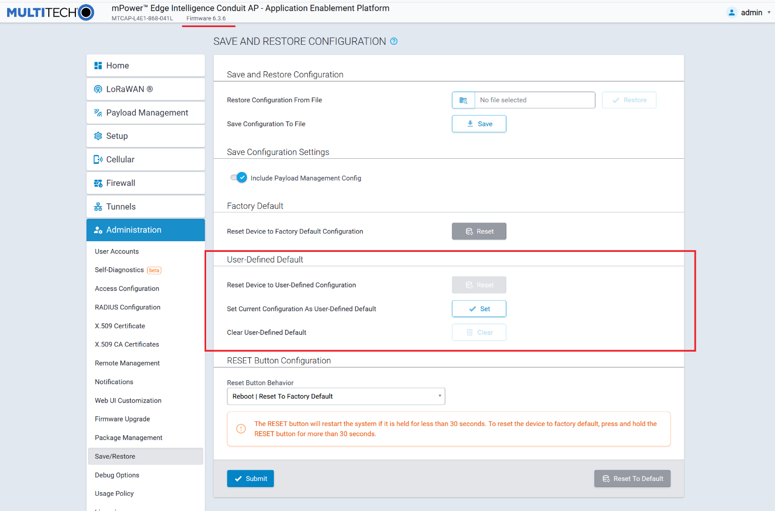
The system does not allow you to set the user-defined default if there are pending changes and the Save and Apply button is red. A warning message appears asking you to first save these changes.

- To set deployment-specific default settings as user-defined defaults, under
Set Current Configuration As User-Defined Default:
- Click Set.
- A dialog box appears prompting you to confirm that you want to save the current configuration as user-defined settings.
- Click OK. This enables the Reset and Clear
buttons.

- To restore the device's configuration to the user-defined configuration
settings, go to Reset Device to User-Defined Configuration under
User-Defined Default:
- Click Reset.
- A dialog box appears prompting you to confirm that you want to restore to a set of user-defined settings.
- Click OK. The device reboots.
- To clear user-defined defaults, under Clear User-Defined Default:
- Click Clear.
- A dialog box appears asking you if you want to clear user-defined default.
- Click OK.
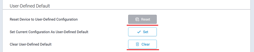
The following options are available from the RESET Button Behavior drop-down list:
- Reboot | Reset To Factory Default (default)
- Reboot | Reset to User Defined Default | Reset To Factory Default
- Reboot | Reset to User Defined Default
- Reboot Only
- Disabled
To reset to factory default settings:
- Select Reboot | Reset to Factory Default from the Reset Button Behavior drop-down list. This option is the default selection.
- Click Submit.
- Click Save and Apply to save your changes. No restart required.
The RESET button will restart the system if it is held for less than 30 seconds. To reset the device to factory default, press and hold the RESET button for more than 30 seconds.

To reset both factory default and user-defined default settings:
- Select Reboot | Reset to User Defined Default | Reset To Factory Default from the Reset Button Behavior drop-down list.
- Click Submit.
- Click Save and Apply to save your changes. No restart required.
The RESET button will restart the system if it is held for less than 10 seconds. To reset the device to user-defined configuration, press and hold the RESET button for 10-30 seconds. Note: if the user-defined configuration is not set, the device will restart when the RESET button is held for 10-30 seconds. To reset the device to factory default, pres and hold the RESET button for more than 30 seconds.

To reset to user-defined default settings:
- Select Reboot | Reset to User-Defined Default from the Reset Button Behavior drop-down list.
- Click Submit.
- Click Save and Apply to save your changes. No restart required.
The RESET button will restart the system if it is held for less than 10 seconds. To reset the device to user-defined configuration, press and hold the RESET button for 10-30 seconds. The RESET button will not allow you to restore the device to factory default. Note: if the user-defined configuration is not set, the device will restart when the RESET button is held for 10-30 seconds.

To reboot only:
- Select Reboot Only from the Reset Button Behavior drop-down list.
- Click Submit.
- Click Save and Apply to save your changes. No restart required.
The RESET button will always restart the system and will not allow you to restore the device to factory default or user-defined configuration.
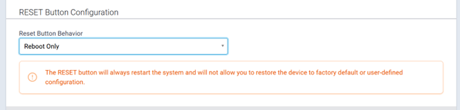
To disable the RESET button:
- Select Disabled from the Reset Button Behavior drop-down list.
- Click Submit.
- Click Save and Apply to save your changes. No restart required.
The RESET button will be disabled. The system will not allow you to restart or restore the device to factory default via the RESET button.
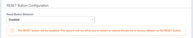
NOTE: Disabling factory default settings means there is no mechanism to restore the device to commissioning mode. Do not lose track of your login credentials or you will lose access to the device.
Warning and Confirmation Messages
Selecting either Reboot | Reset to User Defined Default | Reset To Factory Default or Reboot | Reset to User Defined Default from the Reset Button Behavior drop-down list when the user-defined default configuration is not set results in the following message:
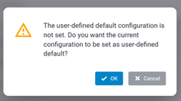
- Click Cancel to exit the message or to set the user-defined default
configuration. This triggers the following message:
- Click OK to set the current configuration as your User-Defined Default.
The system then applies the Reset Button Behavior configuration.
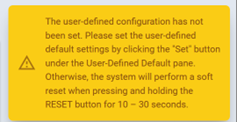
Setting the current configuration as user-defined default settings when the RESET button is not configured to reset to a user-defined default triggers a warning message. The message reminds you to configure the RESET button in the Reset Button Configuration section if you want to be able to reset to a user-defined default via pressing the button:
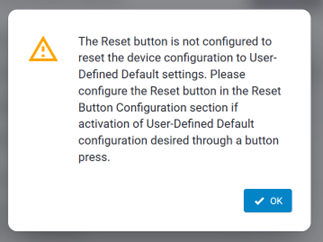
Click OK to close the message. The system continues setting up the current configuration for the user-defined default. The system does not automatically apply the Reset Button Behavior configuration; instead, adjust this option and submit the changes directly, if needed.
Using the Debugging Options
The device has utilities to help troubleshoot and solve technical problems. You can set up your device:
- To automatically reboot itself at a particular time of day or use a particular offset in hours from boot.
- To record and report Syslog messages that can help you resolve potential issues with your device.
You can also communicate directly with the device's cellular radio. To do this:
- From Administration, select Debug Options.
- Click the down arrow to the far right of the Radio Terminal screen to view the terminal window.
- Enter AT commands to the radio.
See other topics for additional Debug Options:
- Auto Reboot Timer (automatically reboot device)
- Call Home Remote Management
- Remote Syslog (configuring syslog)
- Ping and Reset Options
- Data Traffic Statistics
See also: Statistics Configuration Fields
Automatically rebooting the device
To choose a specific time to reboot daily, the amount of time that passes before the device automatically reboots itself, or to disable this function:
- Go Administration > Debug Options > Auto Reboot Timer, select DAILY, TIMER, or DISABLED from the drop-down under Auto Reboot.
- If you chose DAILY, enter the Time of day you want device to reboot (in HH:MM format).
- If you chose TIMER, enter the Interval (in hours) for the amount of time that passes before the device automatically reboots itself.
- If you do NOT want the device to automatically reboot, select DISABLED (default).
Call Home Remote Management
You must have an existing DeviceHQ™ account. This feature enables the device to call home for configuration files, firmware updates, custom applications, and adds your DeviceHQ account key to the device. To enable Call Home Remote Management:
- From Administration, select Debug Options.
- Enable Call Home Remote Management.
- Click Submit.
- To save your changes, click Save and Apply.
Configuring Remote Syslog
To enable and configure Remote Syslog to capture and send log data from your device, you can use a local syslog software or you can setup a log request in DeviceHQ™. In DeviceHQ under Devices, select your device. Then click on Tasks and select Request Device Logs. After the request has been completed, return to the device administration software.
Note: If you change Debug Log Level, it does not require reboot. However, you must reboot the system in order for the log level in /var/log/api.log to be changed.
- To activate Remote Syslog, go to Administration > Debug Options > Remote Syslog, selectEnabled. The Hostname is displayed to the right of Enabled. (Hostname can be modified in the Hostname Configuration pane under Setup > Global DNS page.)
- To enable a remote server to receive and store the device's log data, under Remote Syslog, in the IP Address field, type the IP address of the desired server.
- Select the Protocol used to communicate with the remote syslog server from the drop-down including UDP, TCP, or SSL/TLS.
-
If you select SSL/TLS for Protocol, then click Show to
choose from the following Security Settings:
- Check to enable TLS v1.3, TLS v1.2, or both.
- Select from any or all of the available Cipher Suites based on the version(s) of TLS that you selected. For TLS v1.3: TLS_AES_256_GCM_SHA384, TLS_CHACHA20_POLY1305_SHA256, and TLS_AES_128_GCM_SHA384. For TLS v1.2: ECDHE-RSA-AES256-GCM-SHA384 and ECDHE-RSA-AES128-GCM-SHA256. You can also click Select All.
- Enter the desired Port number that the remote syslog server uses.
- To determine the amount of log information that is collected, under Logging, in the Debug Log Level, select the type of information from the values in the drop- down menu which includes: Minimum, Error, Warning, Info, Debug, and Maximum. The system will collect the type of information you specify. For example, Maximum will collect all the log data available while Warning will collect anything that is a warning or above that level.
- To download syslog information directly from the device, click Download.
- Click Submit.
- To save your changes, click Save and Apply.
Data Traffic Statistics
The Data Traffic Statistics section is used to configure the statistics periodically depending on the configured timeout and data limit. By default, the Save Timeout is set to 300 seconds and the Data Limit is set to 5 MB. For the default scenario, the device saves the data if more than 5 minutes has elapsed, or if more than 5 MB has been sent or received from the last check. The device checks these conditions every minute, but the data is saved only if one of the conditions is met.
To configure Data Traffic Statistics:
- Go to Administration > Debug Options > Data Traffic Statistics.
- Enter the Save Timeout in seconds.
- Enter the Save Data Limit in megabytes.
- Click Submit.
- To save your settings, click Save and Apply.
Statistics Configuration Fields
The device saves the statistics periodically depending on the configured timeout and data limit. By default, the Save Timeout is set to 300 seconds and the Data Limit is set to 5 MB. For the default scenario, the device saves the data if more than 5 minutes has elapsed, or if more than 5 MB has been sent or received from the last check. The device checks these conditions every minute, but the data is saved only if one of the conditions is met.
| Field | Description |
|---|---|
| Save Timeout | The device saves the statistical data when the desired timeout period has elapsed. Default is 300 seconds (5 minutes). |
| Save Data Limit | The device saves the statistical data if the data limit is reached. Default is 5 MB. |
Ping and Reset Options
Perform a Ping Test
Ping allows you to test the IP address or URL to ensure it is operational.
To perform a ping test:
- Go to Administration > Debug Options > Ping.
- Enter the IP address or URL of the site you wish to ping.
- Enter the Number of Requests to set the number of ping requests.
- To forbid fragmentation, check Do Not Fragment. Without fragmentation, the ping fails if the ping packet exceeds MTU size for the network path. By default, the option is disabled.
- Under Network Interface, choose from the available drop-down menu options including: ANY, BRIDGE, CELLULAR, WI-FI WAN, WI-FI AP, ETHERNET (ETH0),, ETHERNET (ETH1), and ETHERNET (ETH2). (Available interfaces vary with hardware model.) NOTE: When using Serial Modem Mode, only the following interfaces are available: ANY, BRIDGE (BR0) and ETHERNET (ETH0).
- Enter the Packet Size (in bytes). This specifies the number of data bytes to be sent. The default is 56, which translates into 84 bytes of data when combined with 8 bytes of ICMP header and 20 bytes of IP header. When specifying 0 bytes, the actual packet size is 28 bytes (ICMP header and IP header).
- Click Ping.
To perform a continuous ping:
- Enter the IP address or URL of the site you wish to continuous ping.
- Enter Packet Size (in bytes). This specifies the number of data bytes to be sent.
- To forbid fragmentation, check Do Not Fragment. Without fragmentation, the ping fails if the ping packet exceeds MTU size for the network path. By default, the option is disabled.
- Under Network Interface, choose from the available drop-down menu options including: ANY, BRIDGE, CELLULAR, WI-FI WAN, WI-FI AP, ETHERNET (ETH0) , ETHERNET (ETH1), and ETHERNET (ETH2). (Available interfaces vary with hardware model.)
- Click Start Continuous Ping to kick off the continuous ping. The system displays a message that ping is in progress.
- The button changes to Stop Continuous Ping. Click the stop button to end the ping. Once done, the system displays the ping results.
Reset Options
- To reset the modem, click Reset Modem.
- To reset Wi-Fi, click Reset Wi-Fi.
-
If you use a Verizon SIM only, click Reset Class 3 APN (Verizon) to initiate the OMA DM procedure, retrieve APN settings from Verizon, and apply them automatically to your modem settings.
- To reset Bluetooth, click Reset Bluetooth
Usage Policy
The device shall provide a Usage Policy for the system. The default usage policy reads as follows:
This system is for the use of authorized users only. Individuals using this system without authority, or in excess of their authority, are subject to having all their activities on this system monitored and recorded by system personnel.
Anyone using this system expressly consents to such monitoring and is advised that if such monitoring reveals possible evidence of criminal activity, system personnel may provide the evidence of such monitoring to law enforcement officials.
This policy displays on the login page. You may modify or add language to the policy as needed.
To view or modify the Usage Policy:
- Go to Administration > Usage Policy.
- The default language appears. You may edit the language directly in the text box.
- When completed, click Submit.
- To save your changes, click Save and Apply.
If at any time you want to return the device to the default setting, click the Reset to Default button in the bottom right corner. (This reverts the Usage Policy back to the default language.)
Licensing
This page shows licenses on this device. Some licenses are factory installed. If you add a licensed feature after receiving the device and have a license file to add:
- Go to Administration > License.
- Click Add New in the upper right corner.
- Add the License Key and Password.
- Click OK.
Status and Logs
Viewing Device Statistics
The device collects sent/received traffic data for WAN, Cellular, and Ethernet networks. The daily statistical data is stored on the device for a 365-day period. All data that is older than 365 days is automatically deleted.
Service Statistics
On the Web Management interface side menu, click Status & Logs > Services to display the Service Statistics window. This window shows the configuration (enabled or disabled) and the status of the following services:
- DDNS
- SNTP
- TCP/ICMP Keep Alive
- Dial-on-Demand
- SMTP
- SMS
- Failover
- SNMP Server
- Security Violation
- Reverse SSH Tunnel
- MQTT Broker
- Remote Management
- LLDP
- Continuous Ping
Mail Log
Mail Log shows the recent email delivery attempts and the mail log details. Mail log entries are sorted by date with the most recent on top. You can select the number of emails to display in the mail log. Possible values are 10, 25, 50, or 100 emails.
- Go to Status & Logs > Mail Log to display the Mail Log window.
- To see the delivery details, click the eye icon under Options for the desired email entry.
- To delete all mail log entries, click Purge Log.Note: Logs do not persist through power cycles.
Mail Queue
Mail Queue shows the emails that are waiting to be sent. The most recent email delivery attempts are on top. You can select the number of emails to display in the queue. Possible values are 10, 25, 50, and 100 emails. Note: Logs do not persist through power cycles.
- Go to Status & Logs > Mail Queue to display the Mail Queue window.
- To view the delivery details for an individual email, click the eye icon under Options for the desired email entry.
Notifications Sent
This page displays attempts to send Notifications via email, SMS, or SNMP.
The list includes the following details of each attempted notification: Date, Message, Recipient Group, and the status of the notification under each communication method including Email, SMS, and SNMP. A check indicates success via that method. An X means failure. No symbol or a blank space indicates that method was not attempted.
To view Notifications Sent:
- Go to Status & Logs > Notifications Sent.
- In the upper right corner, click Refresh to update the list.
- To the right of Refresh, click Delete All Notifications if you want to remove all items in the list.
Apps
Manage Apps
The Manage Apps screen under Apps provides information on installed custom applications including the status and version of all the installed applications.
NOTE: Support for Node-RED/Node.js on Multitech AT91SAM9G25-based products was discontinued within mPower 5.3.0. The option to use Node-RED as a custom application was available from mPower 5.3.3 to 5.3.8. On mPower 6.0 and higher, this option is no longer supported. For details on other methods to create custom applications, see Creating a Custom Application.
Custom Apps
Check Enabled to enable custom applications.
Uncheck Backup On Install if you do not want to backup the currently running application while installing a new version of the application. When checked, the backup is re-installed if the installation of a new version of the app fails.
The Custom Apps section contains the list of custom applications currently installed on the device. Each listing contains the information for a particular application including the name, version, status, and info of the application. The status value can be Started, Running, Stopped, Failed, Install Failed, and Start Failed.
Refer to Creating a Custom Application on the MultiTech Developer Resources website for complete instructions on developing, installing, and deploying custom applications.
To install a new Custom app, click Add Custom App:
- In the App ID field, enter Application ID.
- In the App Name field, enter Application Name.
- Click Browse, go to the location of the custom app, and select the file.
- To install the app, click Install Custom App.
After any changes to this section, click Save and Apply to apply those changes.