MultiConnect® eCell User Guide
About the MultiConnect® eCell
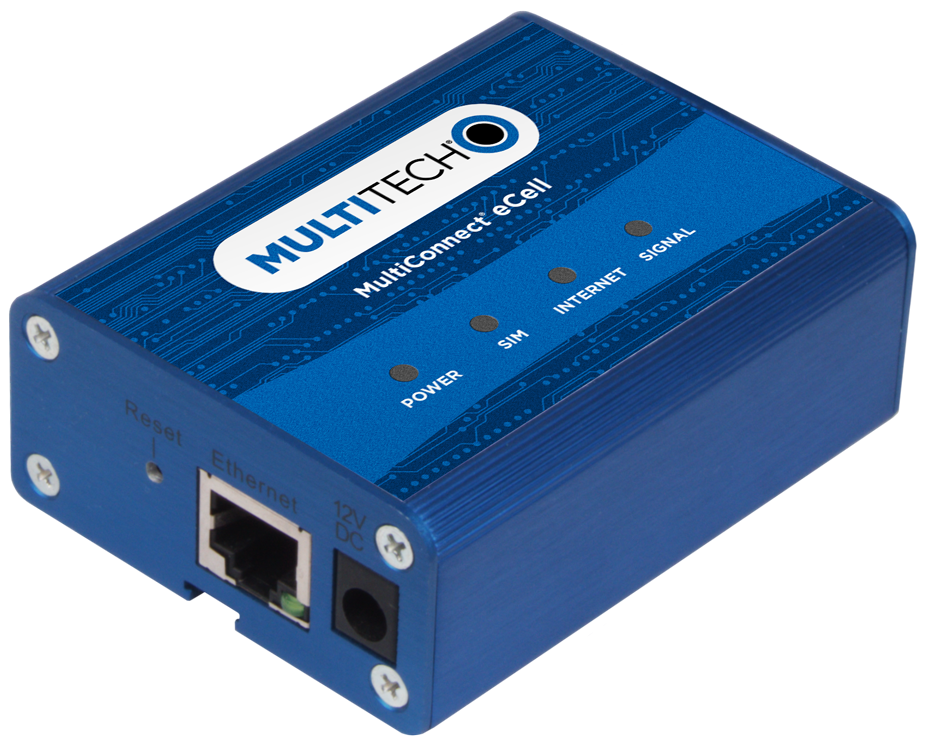
The Multiconnect eCell is an affordable 3G/4G Ethernet to Cellular Bridge used to enable devices with Internet service. It is a simple alternative to complex and expensive cellular routers in applications where advanced networking capabilities are already in place or are not required, but there is a need for remote access without using local wired networks.
Intended Use
MultiConnect eCell cellular to Ethernet bridges are used in a wide variety of private LTE applications such as digital signage, smart vending, smart energy or home medical monitoring. It can also be used to provide main internet broadband and backup access for business continuity; WAN failover or OBM (Out-of-Band Management) path to IT devices at your remote sites. The MultiConnect eCell will help to ensure infrastructure is accessible from anywhere, even during system or network outage. Because they are certified and carrier approved, customers are able to quickly deploy with cellular connectivity to realize new revenue streams, opex reduction or improved service offering.
MultiConnect eCell Ordering Options
| Ordering Part Number | Description | Region |
|---|---|---|
| MTE-LEU6-B07-EU-GB-AU | LTE Cat 4 Cellular to Ethernet Bridge w/EU/GB/AU Accessory Kit (Product is End-Of-Life. Recommended replacement: rCell 300 Series Intelligent Router) |
Australia European Union United Kingdom |
| MTE-LAT6-B07 | LTE Cat 4 Cellular to Ethernet Bridge (Product is End-Of-Life. Recommended replacement: rCell 300 Series Intelligent Router) | United States |
| MTE-L12G1-B07 | Private LTE OnGo CBRS Cat 12 Cellular to Ethernet Bridge (Industrial Temp) w/US Accessory Kit | United States |
Package Contents
| Description | Quantity |
|---|---|
| MultiConnect eCell | 1 |
| Antenna | 2 |
| Mag Mount Adapter (EU SKU Only) | 1 |
| Power Adapter | 1 |
| Ethernet Cable | 1 |
| Four Rubber Feet | 1 |
| Mounting Stick | 1 |
| Quick Start | 1 |
Using DeviceHQ for Device Management
DeviceHQ is a cloud-based device management tool for remote monitoring, upgrades, and configuring devices. For information on creating and using a DeviceHQ account, go to the http://www.multitech.net/developer/software/devicehq/.
Safety Instructions
Operation Safety
ATTENTION: Lisez toutes les instructions et consignes de sécurité avant d'installer ou d'utiliser cet appareil.
- Follow all local laws, regulations, and rules for operating a wireless device.
- Use the device security features to block unauthorized use and theft.
- Unless otherwise noted, antennas are not approved for outdoor use. Do not extend any antenna outside of any building, dwelling, or campus.
- Do not attempt to disassemble the device. There are no user-serviceable parts inside.
- Do not misuse the device. Follow instructions on proper operation and only use as intended. Misuse could make the device inoperable, damage the device or other equipment, or harm users.
- Do not apply excessive pressure or place unnecessary weight on the device. This could result in damage to the device or harm to users.
- Do not use this device in explosive or hazardous environments unless the model is specifically approved for such use. The device may cause sparks. Sparks in explosive areas could cause an explosion or fire that may result in property damage, severe injury, or death.
- Do not expose the device to any extreme environment where the temperature or humidity is high. Such exposure could result in damage to the device or cause a fire. See the device specifications for recommended operating temperature and humidity.
- Do not expose the device to water, rain, or other liquids. It is not waterproof. Exposure to liquids could result in damage to the device.
- Using accessories, such as antennas, that MultiTech has not authorized or that are not compliant with the device accessory specifications may invalidate the warranty.
If the device is not working properly, contact MultiTech technical support.
Ethernet Ports
![]() ATTENTION: Les ports Ethernet et les ports de commande ne sont pas conçus pour être connectés à un réseau de télécommunication public ni utilisés à l'extérieur du bâtiment ou du campus.
ATTENTION: Les ports Ethernet et les ports de commande ne sont pas conçus pour être connectés à un réseau de télécommunication public ni utilisés à l'extérieur du bâtiment ou du campus.
Power Supply Caution
ATTENTION: Pour garantir une protection continue contre les risques d'incendie, remplacez les fusibles uniquement par des fusibles du même type et du même calibre. L'adaptateur doit être installé à proximité de l'appareil et doit être facilement accessible.
VORSICHT: Ersetzen Sie das Netzteil nicht durch ein Netzteil, das für ein anderes Produkt vorgesehen ist. Andernfalls kann das Modem beschädigt werden und Ihre Garantie erlischt. Der Adapter muss in der Nähe des Geräts installiert und leicht zugänglich sein.
UL notice LPS or Class 2
General Safety
The device is designed for and intended to be used in fixed and mobile applications. Fixed means the device is physically secured at one location and cannot be easily moved to another location. Mobile means the device is used in other than fixed locations.
ATTENTION: Maintenir une distance d'au moins 23 cm (9 po) entre l'antenne du récepteur et le corps de l'utilisateur ou à proximité de personnes. Le modem n'est pas conçu pour, ou destinés à être utilisés dans les applications portables, moins de 23 cm (9 po) du corps de l'utilisateur.
Radio Frequency (RF) Safety
Due to the possibility of radio frequency (RF) interference, it is important that you follow any special regulations regarding the use of radio equipment. Follow the safety advice given below.
- Operating your device close to other electronic equipment may cause interference if the equipment is inadequately protected. Observe any warning signs and manufacturers’ recommendations.
- Different industries and businesses restrict the use of cellular devices. Respect restrictions on the use of radio equipment in fuel depots, chemical plants, or where blasting operations are in process. Follow restrictions for any environment where you operate the device.
- Do not place the antenna outdoors.
- Turn off your wireless device when in an aircraft. Using portable electronic devices in an aircraft may endanger aircraft operation, disrupt the cellular network, and may be illegal. Failing to observe this restriction may lead to suspension or denial of cellular services to the offender, legal action, or both.
- Turn off your wireless device when around gasoline or diesel‑fuel pumps and before filling your vehicle with fuel.
- Turn off your wireless device in hospitals and any other place where medical equipment may be in use.
Sécurité relative aux appareils à radiofréquence (RF)
À cause du risque d'interférences de radiofréquence (RF), il est important de respecter toutes les réglementations spéciales relatives aux équipements radio. Suivez les conseils de sécurité ci-dessous.
- Utiliser l'appareil à proximité d'autres équipements électroniques peut causer des interférences si les équipements ne sont pas bien protégés. Respectez tous les panneaux d'avertissement et les recommandations du fabricant.
- Certains secteurs industriels et certaines entreprises limitent l'utilisation des appareils cellulaires. Respectez ces restrictions relatives aux équipements radio dans les dépôts de carburant, dans les usines de produits chimiques, ou dans les zones où des dynamitages sont en cours. Suivez les restrictions relatives à chaque type d'environnement où vous utiliserez l'appareil.
- Ne placez pas l'antenne en extérieur.
- Éteignez votre appareil sans fil dans les avions. L'utilisation d'appareils électroniques portables en avion est illégale: elle peut fortement perturber le fonctionnement de l'appareil et désactiver le réseau cellulaires. S'il ne respecte pas cette consigne, le responsable peut voir son accès aux services cellulaires suspendu ou interdit, peut être poursuivi en justice, ou les deux.
- Éteignez votre appareil sans fil à proximité des pompes à essence ou de diesel avant de remplir le réservoir de votre véhicule de carburant.
- Éteignez votre appareil sans fil dans les hôpitaux ou dans toutes les zones où des appareils médicaux sont susceptibles d'être utilisés.
Interference with Pacemakers and Other Medical Devices
Radio frequency energy (RF) from cellular devices can interact with some electronic devices. This is electromagnetic interference (EMI). The FDA helped develop a detailed test method to measure EMI of implanted cardiac pacemakers and defibrillators from cellular devices. This test method is part of the Association for the Advancement of Medical Instrumentation (AAMI) standard. This standard allows manufacturers to ensure that cardiac pacemakers and defibrillators are safe from cellular device EMI.
The FDA continues to monitor cellular devices for interactions with other medical devices. If harmful interference occurs, the FDA will assess the interference and work to resolve the problem.
Precautions for Pacemaker Wearers
If EMI occurs, it could affect a pacemaker in one of three ways:
- Stop the pacemaker from delivering the stimulating pulses that regulate the heart's rhythm.
- Cause the pacemaker to deliver pulses irregularly.
- Cause the pacemaker to ignore the heart’s own rhythm and deliver pulses at a fixed rate.
Based on current research, cellular devices do not pose a significant health problem for most pacemaker wearers. However, people with pacemakers may want to take simple precautions to be sure that their device doesn't cause a problem.
- Keep the device on the opposite side of the body from the pacemaker to add extra distance between the pacemaker and the device.
- Avoid placing a turned-on device next to the pacemaker (for example, don’t carry the device in a shirt or jacket pocket directly over the pacemaker).
Specifications
| Category | Description |
|---|---|
| General | |
| Performance |
LTE , WCDMA, and GSM |
| Frequency Bands |
Model: MTE-LAT6-B07 LTE: FDD B2/B4/B12 WCDMA: B2/B4/B5 |
|
Model: MTE-LEU6-B07 LTE: FDD B1/B3/B7/B8/B20/B28A, TDD B38/B40/B41 WCDMA: B1/B8 GSM: B3/B8 |
|
|
Model: MTE-L12G1-B07 LTE: FDD B1,2,3,4,5,7,8,9,12,13,14,18,19,20,26,66 TDD B41,42,43,48 WCDMA: B1,2,4,5,6,8,9 |
|
| Radio | |
| Cellular |
MTE-LEU6-B07: 4G LTE Radio with 3G/2G fallback |
|
MTE-LAT6-B07: 4G LTE Radio with 3G fallback |
|
|
MTE-L12G1-B07: 4G LTE CBRS Radio with 3G fallback |
|
| 4G LTE Speed | |
| Packet Data |
Up to 100 Mbps downlink/50 Mbps uplink based on 10/100 Ethernet interface |
| Connectors | |
| Cellular |
Two female SMA connectors |
| SIM Holder |
Mini-SIM 2FF push push SIM |
| Power Requirements | |
| Voltage |
12 VDC @ 1A |
| Physical Description | |
| Dimensions |
3.2" x 2.5" x 1.2" (81.2 x 63.5 x 30.5 millimeters) |
| Weight |
1.0 lbs. (0.45 Kg) |
| Environment | |
| Operating Temperature |
-10° C to +50° C |
| Humidity |
Relative humidity 10% to 93% non-condensing |
| Certifications, Compliance, Warranty | |
| CE Compliance (MTE-LEU6-B07) |
CE RED |
| FCC Compliance (MTE-LAT6-B07) |
FCC Part 15B, 22H, 24E, 27, and IC |
| FCC Compliance (MTE-L12G1-B07) |
FCC Part 15B and Part 96 (Band 48) |
| Network Compliance |
PTCRB and AT&T |
| Safety Compliance |
IEC 60950-1 2es Am2 |
|
IEC 62368-1 |
|
|
CAN/CSA-C22.2 |
|
|
RCM |
|
| Warranty |
Two years |
System Requirements
| Network Requirements |
|
| Browser Requirements |
|
LED Indicators
| Item | Description |
|---|---|
| Power | On: Solid when the device is in normal operational mode. |
| Off: No power. | |
| Flashing: Device is in firmware upgrade mode, recovery mode or needs troubleshooting. | |
| SIM | On: SIM card detected and ready. |
| Off: SIM card not present or not detected. | |
| Flashing: Detecting and Querying SIM card information. | |
| Internet | On: Connection is established and active. |
| Off: No active cellular connection. | |
| Flashing: Active data transferred via cellular. | |
| Signal | On: Solid when there is a strong cellular signal. |
| Off: No cellular signal. | |
| Flashing fast: Medium cellular signal. | |
| Flashing slow: Weak cellular signal. | |
| Ethernet (On the Ethernet port) | On: Solid when there is an Ethernet connection. |
| Off: No Ethernet connection. | |
| Flashing: Data is actively transmitting via the Internet. |
Before Installation
Installing the SIM Card
This device requires a SIM card, which is supplied by your service provider. Install the SIM card before connecting antennas and cabling the device.
To install the SIM card:
- Locate the SIM card slot on the side of the device. The slot is labeled SIM.
- Slide the SIM card into the SIM card slot with the contact side facing down as shown. When the SIM card is installed, it locks into place.

Attaching Antennas and Cables
- Connect the provided antennas to the connectors labeled CELL and AUX. Finger tighten. For best cellular performance, position the top of the antennas as far apart as possible.
- Connect the Ethernet cable between the Ethernet ports on your computer and the device.
- Connect the power adapter to the 12V DC connector.
- To power up the device, plug the power adapter into an electrical outlet.

Installation
Using the Setup Wizard
Configure the device using the web UI. To access the web UI, enter the IP Address into your browser. The default IP Address is 192.168.2.1. If this has been changed, type in the new IP Address.
From the menu on the left, click Wizard.
- Wait 60 seconds after connecting power. The computer gets IP address 192.168.2.100 via DHCP.
- In a web browser, enter IP address 192.168.2.1.
- Login using admin as both the Username and Password. If you are using the default password, it will prompt you to change it for future logins.
- Click Wizard on the left.
- Click Next.
- Change password, if desired and click Next. (Recommended)
- Set the device's Time Zone and click Next.
- Enter and configure APN.
- Select Manual Configuration.
- Set Country to Others.
- Enter the APN provided by the SIM provider.
- Click Next.
- Click Apply.
- Wait a few minutes and check LED status. Power, SIM, Internet, and Signal LEDs are on when there is a live Internet connection. For more information on the LEDs, refer to LED Indicators.
After the device has a valid Internet connection, your computer automatically renews to the new IP address assigned to cellular connection and has full access to the Internet.
Basic Network
WAN and Internet Setup
This device has Cellular WAN interfaces. Configure these individually to maximize Internet connection setup.
To configure Cellular WAN settings go to Basic Network > WAN on the menu on the left.
Ethernet LAN
This device has one Ethernet LAN port to connect to one external Ethernet device. To configure, on the menu on the left go to Basic Network > LAN.
- Site Name: Enter the Site name to identify the location when setting up DeviceHQ.
- LAN IP Address: Enter the LAN's IP address. This IP address must be used as the computer's default gateway. This is also the IP address of the web UI. If you change this, type in the new IP address into a web browser to see the web UI.
- Subnet Mask: Enter the LAN's subnet mask. This defines how many clients are allowed in one network or subnet. The default subnet is 255.255.255.0 and allows for a maximum of 254 IP addresses.
NAT
This option appears when NAT mode is selected in the WAN internet setup page. This mode allows multiple LAN devices to share one cellular WAN connection.
- Configuration: Check option for NAT loopback. Allows you to access the WAN IP address from inside your LAN network.
- Virtual Server: Allows you to setup the WAN IP to LAN IP mapping in order
for remote access to LAN devices.
- Public Port: Enter the public IP port number.
- Server IP: Enter the LAN device IP address.
- Private Port: Enter the LAN device IP port number.
- Protocol: Select TCP or UDP or both.
- Time Schedule: Select a time schedule when this rule will take effect.
- Rule: Check to enable the rule.
- DMZ (Demilitarized Zone) Host: This is a host without the protection of a
firewall. It allows a computer to be exposed to unrestricted 2-way communication
from the Internet. If a specific application is blocked by NAT mechanism, you
can designate that LAN computer as a DMZ host to solve this problem.Note: This feature should only be used when necessary.
Routing
Static Routing
If there is more than one router and subnet, enable the routing function to allow packets to find proper routing paths and allow different subnets to communicate with each other.
For static routing, you can specify up to 16 routing rules. These rules allow you to determine which physical interface addresses are being used for outgoing data. For each rule, enter the destination IP address, subnet mask, gateway, and hop. Check Enable or Disable.
Dynamic DNS
To host a server on a changing IP address, you have to use dynamic domain name service (DDNS). DDNS maps the name of your host to the current IP address, which changes each time you connect to your ISP. Before you enable DDNS, you need to register an account on one of the DDNS servers in the provider list. To configure, from the menu on the left choose Basic Network > Client/Server.
- DDNS: Check Enable.
- Provider: The DDNS provider supports a service to bind your IP with a certain domain name.
- Host Name: Register a domain name to the DDNS provider.
- Username/email: Enter a username or email based on the DDNS provider requirements.
- Password/Key: Enter a password or key based on the DDNS provider requirements.
DHCP Server
The gateway supports DHCP server to serve the DHCP requests from a LAN device. There is one default LAN IP address that is the same as the gateway LAN interface. The subnet mask is 255.255.255.0, and the IP Pool ranges from .100 to .200 as shown on the following DHCP Server List. To edit one DHCP server configurations, click Edit at the end of the DHCP server information.
There is one additional option to show the DHCP client list and IP addresses of local client hosts.
To configure, from the menu on the left choose Basic Network > Client/Server.
- DHCP Server Name: Name of the DHCP server. This is optional.
- LAN IP Address: Specify the local IP address of the enabled DHCP Server. This is the LAN IP address of this gateway for the DHCP server. Normally, this IP address is also the default gateway of local computers and devices.
- Subnet Mask: Select the subnet mask for the DHCP server. The subnet mask defines how many clients are allowed in one network or subnet. The default subnet mask is 255.255.255.0/24. This means a maximum of 254 IP addresses are allowed in the subnet. However, the gateway's LAN IP occupies one of them.
- IP Pool Starting/Ending Address: Specify the IP address pool's
starting/ending addresses. When there is a request, the DHCP server will
automatically allocate an unused IP address from the IP address pool to the
requesting computer. Note: The number of IP addresses in this IP pool must be less than the maximum number of subnet networks according to the set subnet mask.
- Lease Time: DHCP lease time to the DHCP client.
- Domain Name: This information is passed to the clients. This is optional.
- Primary DNS/Secondary DNS: Assign DNS Servers. This is optional.
- Primary WINS/Secondary WINS: Assign WINS Servers. This is optional.
- Gateway: This is the alternate Gateway IP address. Assign another gateway to your computer when the DHCP server offers an IP address. For example, the gateway will assign an IP address to local computers but they will access the Internet through another gateway. This is optional.
- Server: To activate the DHCP server, check Enable.
System Management (DeviceHQ)
Signing Up with DeviceHQ and Setting Up MTE to Communicate with DeviceHQ
- Register and sign up a new account at https://www.devicehq.com.
- Log in to https://www.devicehq.com and generate a device API key using the
following steps:
- Select Account info (to the right of the account email address) and click Edit.
- Check Device API Enabled and click Update Account.
- Click Generate new Device API Keys.
- Write down and save "Device API Secret" and "Device API Auth Token",
these two keys are required during MTE device setup. Note: DO NOT lose these keys since there is no way to see them again.
Setting Up MTE UI for DeviceHQ
MTE must be running firmware version 2.04 or above for DeviceHQ support. Download firmware from the website and upgrade the device before proceeding. https://www.multitech.com/models/92506980LF
- In Basic Network, on the LAN Setup Screen: Enter and Define Site Name so it shows as Description in DeviceHQ
- In Basic Network, on the System Management Setup Screen: DeviceHQ access setup
requires:
- Check the Enable option.
- Enter DeviceHQ account API secret and API Auth Token.
- Click Save.
Wait for a few minutes. If MTE has an active cellular internet connection, it automatically checks in and registers with DeviceHQ. Log in to DeviceHQ and make sure the new MTE device shows up on your account.
Setting Up a New Firmware File on DeviceHQ
This is performed after logging in to DeviceHQ.
- Click Files and click the New Firmware button.
- Select model = Unspecified.
- Enter the name and version number of the firmware file.
- Choose the firmware BIN file.
- Click the Upload button.
- Make sure MD5 checksum matches on the firmware BIN file.
Pushing a Firmware Update to All Devices
This is performed after logging in to DeviceHQ.
- Check all the devices.
- Click Tasks and select Upgrade Firmware.
- Select the firmware file you want to push to the devices.
- Click OK.
This schedules a new firmware push to all devices the next time they check in.
Pushing a Firmware Update to One Device
This is performed after logging in to DeviceHQ.
- Click on the individual device to view more details.
- Click Schedule, select Upgrade Firmware, and select the firmware file.
- Click OK when prompted.
Setting Up a Configuration File on DeviceHQ
This is performed after logging in to DeviceHQ.
- Click the Files tab.
- Click New Configuration.
- Enter the configuration file's name and description.
- Choose the configuration ZIP file (zip up the configuration BIN file into a .zip file).
- Click Upload.Note: MTE configuration BIN files must be created using an external device and saved as backup, then the BIN file must be a .zip file when uploaded to DeviceHQ. Name the ZIP file based on device description or serial number so it can be easily identified.
Pushing a Configuration File to a Single Device
- Click on the individual device to view more details.
- Click Schedule, select Upgrade Config, and select the config file.
- Click OK when prompted.
Requesting Device Log Files
- Click on the individual device to view more details.
- Click Schedule and select Request Device Logs.
- Click OK when prompted.
Requesting a Device Reboot
- Click on the individual device to view more details.
- Click Schedule and select Reboot.
- Click OK when prompted.
MTE Data Usage with DeviceHQ
- Each time a device checks in, it can take up to 23 KB.
- Log file upload can vary depending on the size of the log files.
- Configuration file size can be up to 12 KB.
- MTE firmware file size is approximately 9 MB.
Advanced Network
Advanced Network
This section is only available when NAT mode is selected in the WAN cellular internet setup. Enable/disable firewall, Stealth Mode, SPI, and Discard PING from the WAN interface.
Configuration
- Firewall: Enable / Disable Firewall.
Options
- Stealth Mode: When enabled, the router will not respond to port scans from the WAN. This makes the router less susceptible to discovery and attacks.
- SPI (Stateful Packet Inspection): Also known as dynamic packet filtering. This helps to prevent cyber attacks by tracking more states per session. It validates that the traffic passing through that session conforms to the protocol.
- Discard PING from WAN side: When enabled, this gateway won't reply to any ICMP request packets from the WAN side.
System
This section includes system information, system logs, system tools (i.e. firmware updates), scheduling, and external syslog server setup.
Change Password
- Old, New, and Confirmation Password: To change your password, type in your old password, then enter in the new password in the new password and confirm password fields. Click Save to store your settings or Undo to cancel the changes.
- Administrator Time-out: Other options allow you to set when there are no activities on the web user interface.
- Telnet with CLI: Check to Enable CLI access via LAN or WAN.
- Connection Type: Check to Enable Telnet or SSH access via LAN or WAN. The Telnet and SSH access IP port number can be configured to use custom port.
- Options: Setup local or remote HTTP or HTTPS web UI access. Enter unique remote IP address and subnet mask to restrict remote web UI access. Enable web UI access for LAN and/or WAN interfaces. Port settings apply to WAN web UI access only.
System Information
This section displays System Information for the WAN interface and the current date and time.
System Status
System Status displays and captures log information. It also allows log files to be sent to an external syslog server.
- Web Log: Check Enable for System, Attacks, Drop, and Debug categories, then click Save. Click View to display or download log files.
- Syslog: Check to Enable logging to an external syslog server. The external syslog server's IP address can be configured using the External Servers option.
System Tools
Options to setup system time, perform firmware updates, ping test, trace route test, reboot or schedule a reboot, reset to factory defaults, wake up on LAN, and backup configuration settings.
- System Time: Configure the time zone. You can select sync current time and date with external time server or local PC time.
- Firmware Upgrade/Configuration Restore: Perform firmware upgrade or
restore a backup configuration file.Note: To check the current firmware version, refer to the top of the page after login.
- Reboot: Select reboot now or set a schedule for an auto-reboot to occur.
- Reset to Default: Resets all settings back to factory defaults.
- Backup/Restore Configuration Settings: Save all current settings to a configuration file or restore a backup configuration file.
Scheduling
- Enable the schedule function and setup a rule for each schedule. The rule can be used in many other functions, such as scheduling an auto-reboot, scheduling an auto WAN connectivity, etc.
- Click Save to store all schedule settings.
External Servers
- Click Add to add and configure an external syslog server. The server will allow logging to be captured via an external syslog server.
- Click Save to save all the server settings.
Disposal
Instructions for Disposal of WEEE by Users in the European Union
The symbol shown below is on the product or on its packaging, which indicates that this product must not be disposed of with other waste. Instead, it is the user's responsibility to dispose of their waste equipment by handing it over to a designated collection point for the recycling of waste electrical and electronic equipment. The separate collection and recycling of your waste equipment at the time of disposal will help to conserve natural resources and ensure that it is recycled in a manner that protects human health and the environment. For more information about where you can drop off your waste equipment for recycling, contact your local city office, your household waste disposal service or where you purchased the product.
|
July, 2005 |
Regulatory Information
FCC 47 CFR Part 15 Regulation Class B Devices
This equipment has been tested and found to comply with the limits for a Class B digital device, pursuant to part 15 of the FCC Rules. These limits are designed to provide reasonable protection against harmful interference in a residential installation. This equipment generates, uses, and can radiate radio frequency energy and, if not installed and used in accordance with the instructions, may cause harmful interference to radio communications. However, there is no guarantee that interference will not occur in a particular installation.
If this equipment does cause harmful interference to radio or television reception, which can be determined by turning the equipment off and on, the user is encouraged to try to correct the interference by one or more of the following measures:
- Reorient or relocate the receiving antenna.
- Increase the separation between the equipment and receiver.
- Connect the equipment into an outlet on a circuit different from that to which the receiver is connected.
- Consult the dealer or an experienced radio/TV technician for help.
FCC Interference Notice
- This device may not cause harmful interference, and
- This device must accept any interference received, including interference that may cause undesired operation.
Industry Canada Class B Notice
This Class B digital apparatus meets all requirements of the Canadian Interference‑Causing Equipment Regulations.
This device complies with Industry Canada license‑exempt RSS standard(s). The operation is permitted for the following two conditions:
- The device may not cause interference, and
- This device must accept any interference, including interference that may cause undesired operation of the device.
Cet appareil numérique de la classe B respecte toutes les exigences du Reglement Canadien sur le matériel brouilleur.
Le présent appareil est conforme aux CNR d'Industrie Canada applicables aux appareils radio exempts de licence. L'exploitation est autorisée aux deux conditions suivantes:
- L'appareil ne doit pas produire de brouillage, et
- L'appareil doit accepter tout brouillage radioélectrique subi, même si le brouillage est susceptible d’en compromettre le fonctionnement.
EU RoHS 3 Directive
MultiTech confirms that all products comply with the chemical concentration limitations set forth in the Restriction of Hazardous Substances in Electrical and Electronic Equipment (RoHS 3) regulations for CE and UKCA, following the standard EN IEC 63000:2018.
For the current Certificate of Compliance for Hazardous Substances and additional regulatory documents, go to https://multitech.com/approvals-and-certifications/.
FCC Requirements
There cannot be any alteration to the authorized antenna system. The antenna system must be the same type with similar in‐band and out‐of‐band radiation patterns and should not exceed the maximum gain information detailed in the FCC Grant.
EU EMC, Safety, and Radio Equipment Directive (RED) Compliance
![]() The CE mark is affixed to this product to confirm compliance with the following European Community Directives:
The CE mark is affixed to this product to confirm compliance with the following European Community Directives:
- Council Directive 2011/65/EU on the restriction of the use of certain hazardous substances in electrical and electronic equipment; and
- Council Directive 2014/53/EU on radio equipment and telecommunications terminal equipment and the mutual recognition of their conformity.
MultiTech declares that this device is in compliance with the essential requirements and other relevant provisions of Directive 2014/53/EU. The declaration of conformity may be downloaded at https://multitech.com/product-support/.
Accessories
To find information on accessories for your product, go to https://multitech.com/all-products/accessories/.