rCell 300 Series Router Hardware Guide
About the rCell 300
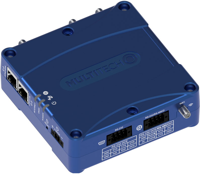
The rCell 300 Series router, also known as the rCell 300, is both an industrial router and a specialized network device designed to connect internet-of-things (IoT) devices to the internet. The rCell 300 provides enhanced security to protect against cyber threats, includes edge intelligence to run local applications, and offers secure data communication between many types of devices that use legacy or the latest communication technologies. The MultiTech Cloud Services platform is included with the rCell 300 to secure, scale, and manage your application.
Intended Use
The rCell 300 is designed for a variety of industrial and IoT applications. Some of its intended uses include:
- Remote monitoring and control: This device is ideal for remote monitoring and control of equipment and systems in industries such as oil and gas, utilities, and agriculture. The rCell 300 allows for real-time data collection and management from remote locations.
- Smart cities and infrastructure: This device can be used in smart-city applications, including traffic management, environmental monitoring, and electric vehicle charging stations.
- Industrial automation: This device supports industrial automation by connecting various sensors and devices, enabling efficient and automated processes.
The rCell 300 can be used in applications that require equipment to operate in extreme cold and hot environments. For outdoor deployments, the rCell 300 must be installed in a waterproof enclosure.
In the Box
Some options don't include all of the items shown below. See rCell 300 Ordering Options.
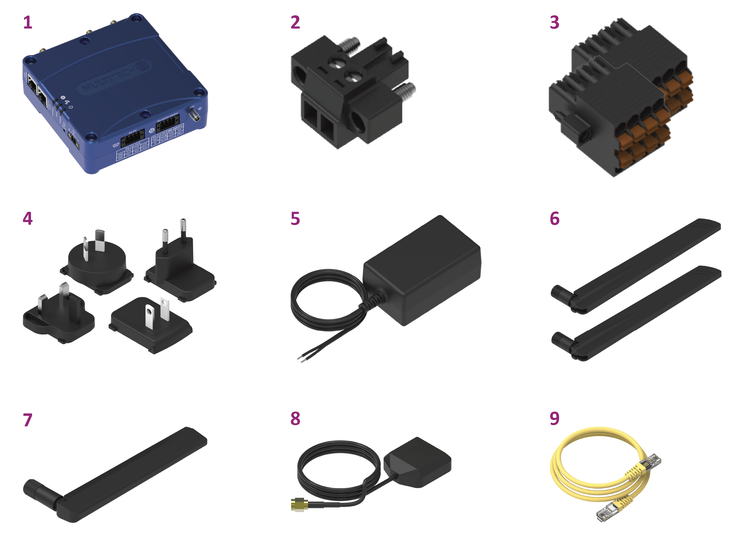
| Item | Description | Quantity |
|---|---|---|
| 1 | rCell 300 LTE Cat 4 cellular router with fallback | 1 |
| 2 | 2-wire terminal block (power) | 1 |
| 3 | 8-wire terminal block (serial, GPIO) | 2 |
| 4 | AU/NZ, EU, GB, US power blade set | 1 |
| 5 | Power supply with stripped wires | 1 |
| 6 | Cellular (LTE) antenna | 2 |
| 7 | Wi-Fi antenna1 | 1 |
| 8 | GPS antenna | 1 |
| 9 | Ethernet CAT5e cable, 6 ft | 1 |
| 10 | Quick-start guide (not shown) | 1 |
| 11 | Registration card (not shown) | 1 |
rCell 300 Ordering Options
| Ordering Part Number | In the Box Items Included | Region |
|---|---|---|
| MTR3‑L4G2D‑AC00PA‑EWM | All items (with Wi-Fi) |
Australia Canada European Union United Kingdom United States |
| MTR3‑L4G2D‑AC00QA‑EWM | All items except 7 (without Wi-Fi) | |
| MTR3‑L4G2D‑AC00PA‑11M | Only items 1, 2, 3, 10, and 11 (with Wi-Fi) | |
| MTR3‑L4G2D‑AC00QA‑11M | Only items 1, 2, 3, 10, and 11 (without Wi-Fi) |
Wi-Fi antenna, GPS antenna, and other accessories are available for all ordering options. See Accessories.
Required Tools
- 2.0 mm slotted screwdriver
- 2.5 mm slotted screwdriver
- #1 Phillips screwdriver
- #2 Phillips screwdriver
Safety Instructions
Operation Safety
Attention: Lisez toutes les instructions et consignes de sécurité avant d'installer ou d'utiliser cet appareil.
- Follow all local laws, regulations, and rules for operating a wireless device.
- Use the device security features to block unauthorized use and theft.
- Unless otherwise noted, antennas are not approved for outdoor use. Do not extend any antenna outside of any building, dwelling, or campus.
- Do not attempt to disassemble the device. There are no user-serviceable parts inside.
- Do not misuse the device. Follow instructions on proper operation and only use as intended. Misuse could make the device inoperable, damage the device or other equipment, or harm users.
- Do not apply excessive pressure or place unnecessary weight on the device. This could result in damage to the device or harm to users.
- Do not use this device in explosive or hazardous environments unless the model is specifically approved for such use. The device may cause sparks. Sparks in explosive areas could cause an explosion or fire that may result in property damage, severe injury, or death.
- Do not expose the device to any extreme environment where the temperature or humidity is high. Such exposure could result in damage to the device or cause a fire. See the device specifications for recommended operating temperature and humidity.
- Do not expose the device to water, rain, or other liquids. It is not waterproof. Exposure to liquids could result in damage to the device.
- Using accessories, such as antennas, that MultiTech has not authorized or that are not compliant with the device accessory specifications may invalidate the warranty.
If the device is not working properly, contact MultiTech technical support.
Hot Caution
![]() WARNING! HOT SURFACE DO NOT TOUCH
WARNING! HOT SURFACE DO NOT TOUCH
![]() AVERTISSEMENT! SURFACE CHAUDE NE PAS TOUCHER
AVERTISSEMENT! SURFACE CHAUDE NE PAS TOUCHER
Attention: En fonction du mode de fonctionnement et de l'environnement auquel l'appareil est soumis, le boîtier métallique peut devenir chaud au toucher.
Ethernet Ports
![]() ATTENTION: Les ports Ethernet et les ports de commande ne sont pas conçus pour être connectés à un réseau de télécommunication public ni utilisés à l'extérieur du bâtiment ou du campus.
ATTENTION: Les ports Ethernet et les ports de commande ne sont pas conçus pour être connectés à un réseau de télécommunication public ni utilisés à l'extérieur du bâtiment ou du campus.
Customer‑Provided Power Supply and Power Cable
MultiTech warranty/UL Certification does not apply or extend to the device’s safety certification of voltages outside the certified range. Optional power supply operating temperature and installation location determines the maximum operation temperature of the device.
A customer-provided power cable must be connected to a certified LPS power source. Using a customer-provided DC power cable does not apply or extend to the device’s safety certification or MultiTech warranty. Cord length and wire composition must be taken into consideration to determine voltage drops and safety hazards of wire routing.
Radio Frequency (RF) Safety
Due to the possibility of radio frequency (RF) interference, it is important that you follow any special regulations regarding the use of radio equipment. Follow the safety advice given below.
- Operating your device close to other electronic equipment may cause interference if the equipment is inadequately protected. Observe any warning signs and manufacturers’ recommendations.
- Different industries and businesses restrict the use of cellular devices. Respect restrictions on the use of radio equipment in fuel depots, chemical plants, or where blasting operations are in process. Follow restrictions for any environment where you operate the device.
- Do not place the antenna outdoors.
- Turn off your wireless device when in an aircraft. Using portable electronic devices in an aircraft may endanger aircraft operation, disrupt the cellular network, and may be illegal. Failing to observe this restriction may lead to suspension or denial of cellular services to the offender, legal action, or both.
- Turn off your wireless device when around gasoline or diesel‑fuel pumps and before filling your vehicle with fuel.
- Turn off your wireless device in hospitals and any other place where medical equipment may be in use.
Sécurité relative aux appareils à radiofréquence (RF)
À cause du risque d'interférences de radiofréquence (RF), il est important de respecter toutes les réglementations spéciales relatives aux équipements radio. Suivez les conseils de sécurité ci-dessous.
- Utiliser l'appareil à proximité d'autres équipements électroniques peut causer des interférences si les équipements ne sont pas bien protégés. Respectez tous les panneaux d'avertissement et les recommandations du fabricant.
- Certains secteurs industriels et certaines entreprises limitent l'utilisation des appareils cellulaires. Respectez ces restrictions relatives aux équipements radio dans les dépôts de carburant, dans les usines de produits chimiques, ou dans les zones où des dynamitages sont en cours. Suivez les restrictions relatives à chaque type d'environnement où vous utiliserez l'appareil.
- Ne placez pas l'antenne en extérieur.
- Éteignez votre appareil sans fil dans les avions. L'utilisation d'appareils électroniques portables en avion est illégale: elle peut fortement perturber le fonctionnement de l'appareil et désactiver le réseau cellulaires. S'il ne respecte pas cette consigne, le responsable peut voir son accès aux services cellulaires suspendu ou interdit, peut être poursuivi en justice, ou les deux.
- Éteignez votre appareil sans fil à proximité des pompes à essence ou de diesel avant de remplir le réservoir de votre véhicule de carburant.
- Éteignez votre appareil sans fil dans les hôpitaux ou dans toutes les zones où des appareils médicaux sont susceptibles d'être utilisés.
Interference with Pacemakers and Other Medical Devices
Radio frequency energy (RF) from cellular devices can interact with some electronic devices. This is electromagnetic interference (EMI). The FDA helped develop a detailed test method to measure EMI of implanted cardiac pacemakers and defibrillators from cellular devices. This test method is part of the Association for the Advancement of Medical Instrumentation (AAMI) standard. This standard allows manufacturers to ensure that cardiac pacemakers and defibrillators are safe from cellular device EMI.
The FDA continues to monitor cellular devices for interactions with other medical devices. If harmful interference occurs, the FDA will assess the interference and work to resolve the problem.
Precautions for Pacemaker Wearers
If EMI occurs, it could affect a pacemaker in one of three ways:
- Stop the pacemaker from delivering the stimulating pulses that regulate the heart's rhythm.
- Cause the pacemaker to deliver pulses irregularly.
- Cause the pacemaker to ignore the heart’s own rhythm and deliver pulses at a fixed rate.
Based on current research, cellular devices do not pose a significant health problem for most pacemaker wearers. However, people with pacemakers may want to take simple precautions to be sure that their device doesn't cause a problem.
- Keep the device on the opposite side of the body from the pacemaker to add extra distance between the pacemaker and the device.
- Avoid placing a turned-on device next to the pacemaker (for example, don’t carry the device in a shirt or jacket pocket directly over the pacemaker).
Vehicle Safety
When using your device in a vehicle:
- Do not use this device while driving.
- Respect local regulations on the use of cellular devices in vehicles.
- If incorrectly installed in a vehicle, operating the wireless device could interfere with the vehicle’s electronics. To avoid such problems, use qualified personnel to install the device. The installer should verify that the vehicle electronics are protected from interference.
- Using an alert device to operate a vehicle’s lights or horn is not permitted on public roads.
- UL evaluated this device for use in ordinary locations only. UL did not evaluate this device for installation in a vehicle or other outdoor locations. UL certification does not apply or extend to use in vehicles or outdoor applications.
Specifications
| Category | Description |
|---|---|
| General | |
| Regions | Australia, Canada, European Union, United Kingdom, United States |
| Cellular module performance | 3GPP release 10 |
| 4G‑LTE FDD/TDD category 4 | |
| 150 Mbps peak downlink/50 Mbps peak uplink with 3G/2G fallback | |
| Frequency bands (MHz) | 4G LTE FDD (Europe): B3 (1800), B7 (2600), B8 (900), B20 (800) |
| 2G (Europe fallback): B2 (1900), B3 (1800), B5 (850), B8 (900) | |
| 4G LTE FDD (AT&T): B2 (1900), B4 (AWS1700), B12 (700), B14 (700) | |
| 4G LTE FDD (Verizon): B2 (1900), B4 (AWS1700), B13 (700) | |
| 4G LTE FDD (Anterix): B8‑US (900) | |
| 4G LTE FDD (APAC): B1 (2100), B9 (1800), B18 (800), B19 (850), B26 (850), B28 (700) | |
| 3G: B1 (2100), B2 (1900), B4 (AWS1700), B5 (850), B6, B8 (900), B19 (850) | |
| 2G: B2 (1900), B3 (1800), B5 (850), B8 (900) | |
| 4G LTE FDD bands: B25 (1900) | |
| SMS | Mobile Originate, Mobile Terminated, Point‑to‑Point |
| Wi‑Fi, AC00PA models | IEEE 802.11a/b/g/n/ac/ax (2.4 and 5 GHz) |
| GNSS, all models | GNSS connections: 3 |
| GNSS systems supported: default; concurrent GPS/QZSS/SBAS and GLONASS | |
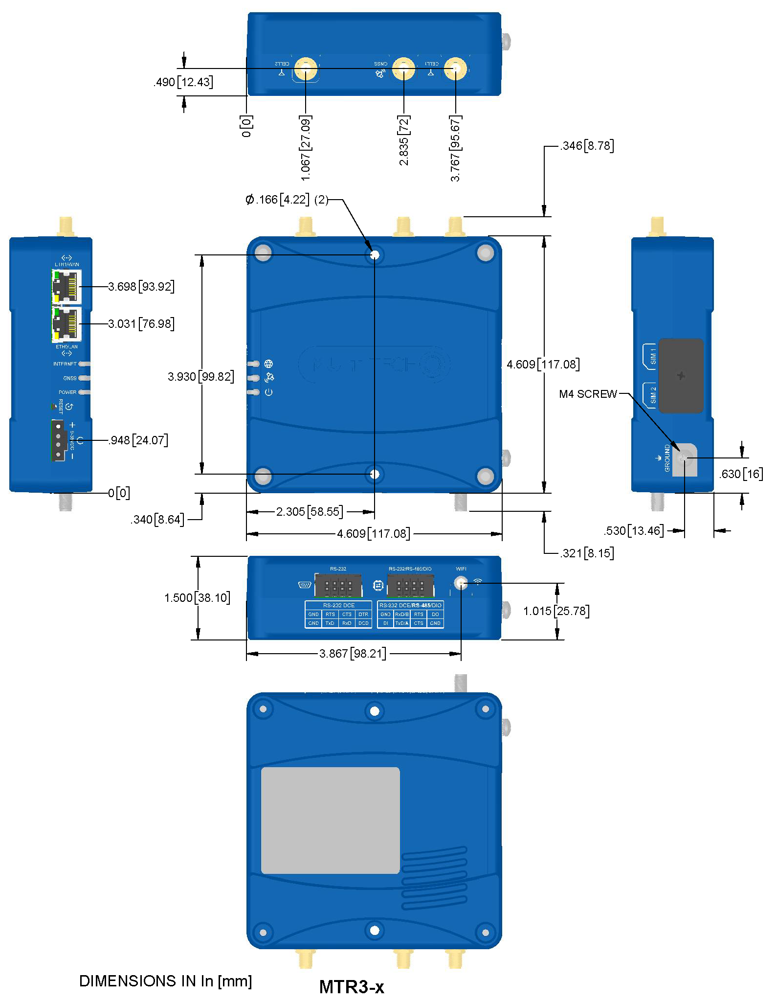
| Physical Description | |
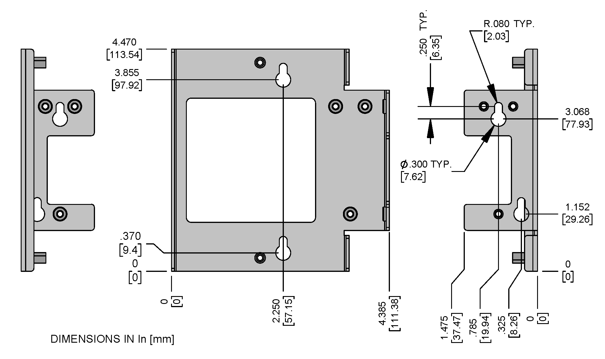
| Dimensions | 117 mm × 117 mm × 38 mm (4.61 in. × 4.61 in. × 1.50 in.) |
| Weight | 0.5 kg (1 lb) |
| Chassis | Aluminum (IP30 rating) |
| Mounting options | Desktop |
| Wall mount (using Wall‑Mount accessory) | |
| DIN rail mount (using DIN‑Mount accessory) | |
| Power Requirements | |
| Input voltage | 9–36 VDC at 1 A |
| Power at 12 VDC | Idle: 2.4 W (200 mA) |
| Maximum: 6.5 W (542 mA) | |
| Environmental | |
| Operating temperature | −40 °C to 75 °C (−40 °F to 167 °F) |
| Storage temperature | −40 °C to 85 °C (−40 °F to 185 °F) |
| Relative humidity | 15%–93% RH non‑condensing |
| Certifications | |
| EMC and radio compliance | CE, FCC, IC, RCM, UKCA |
| Safety compliance | UL/cUL 62368‑1 3rd Edition |
| IEC 62368‑1 3rd Edition including IP30 | |
| AS/NZS 62368.1 3rd Edition | |
| Network compliance | PTCRB |
| Network operator | AT&T, Verizon |
| Quality | MIL‑STD‑810G: High Temp, Low Temp, Cold Dwell, Random Vibration, and Sine Vibration |
| SAE J1455: Random Vibration and Sine Vibration | |
| Warranty | 2 years, https://www.multitech.com/warranty/ |
Device Dimensions
rCell 300 Serial Label
This is an example serial label. Actual labels vary depending on the regulatory approval markings and device model.
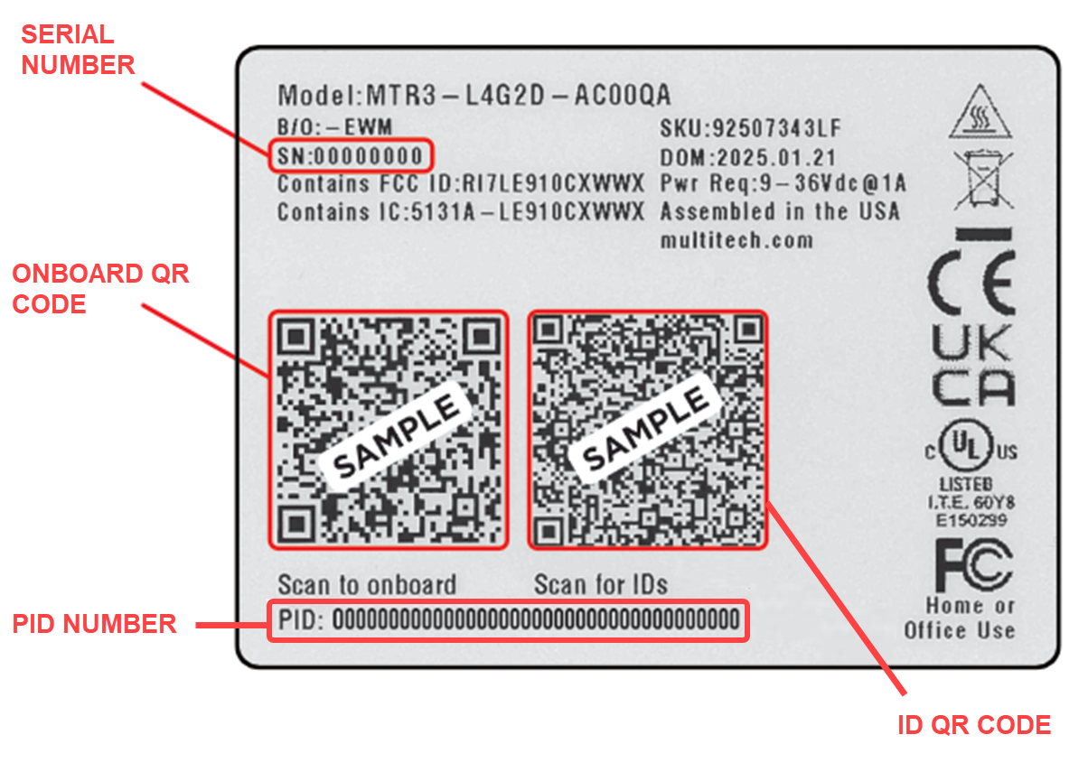
- The onboard QR code provides a link for onboarding the device.
- The ID QR code provides the following product information:
- MultiTech model/ordering part number
- Serial number
- UUID (universally unique identifier)
- IMEI (international mobile equipment identity)
- ICCID (integrated circuit card identification); only if the device is shipped with a SIM card installed
- PID (provisioning identifier)
- Hardware version
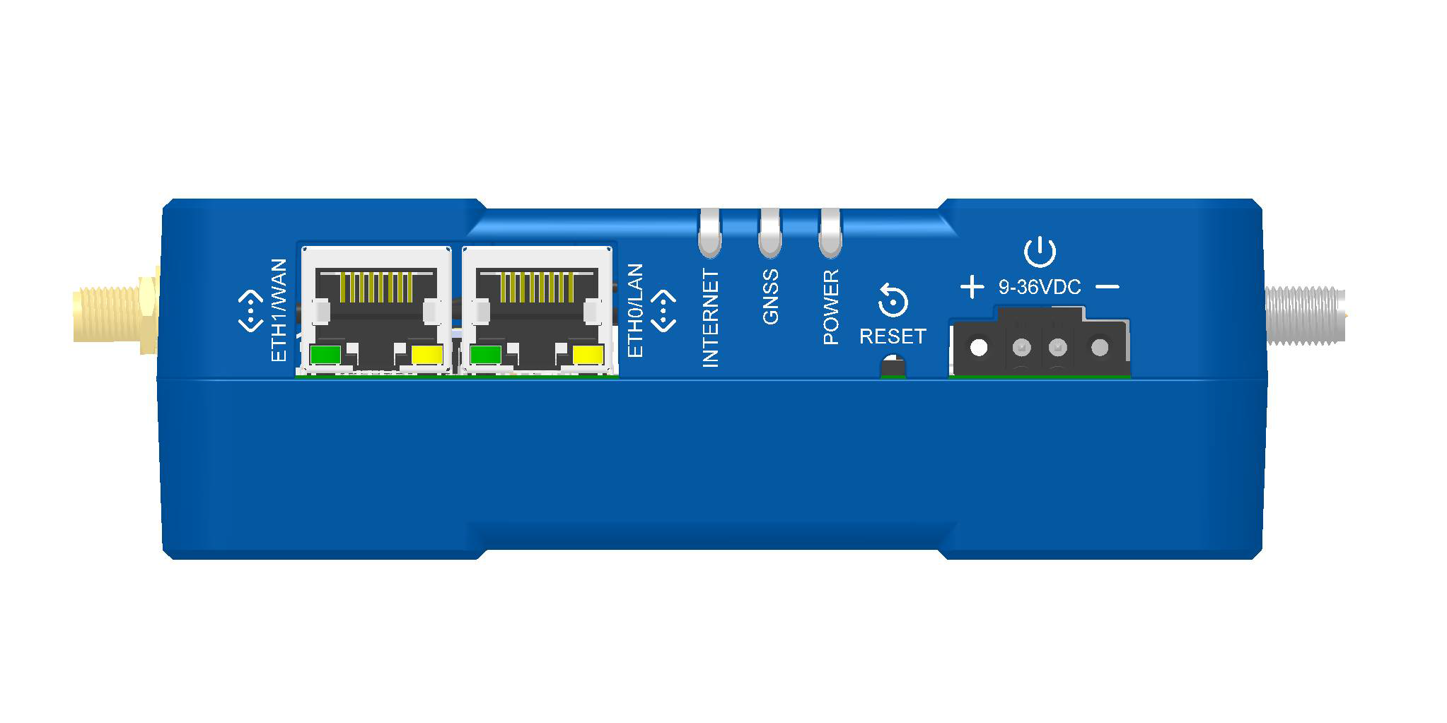
Device Connectors
| Label | Description |
|---|---|
| CELL 1, CELL 2 | Main antenna (CELL 1) and diversity antenna (CELL 2) antenna inputs; use with two Cat 4 LTE antennas; SMA(F) |
| GNSS | GNSS antenna input; use with one GNSS antenna; SMA(F) |
| WI-FI | Wi‑Fi antenna input; use with one Wi‑Fi antenna (varies with model); RP-SMA(F) |
| GROUND | Connection to earth ground |
| SIM1, SIM2 | Receptacles for SIM card(s); Micro SIM (3FF) 1.8 V and 3 V (under SIM door) |
| RESET | Reset button; see Reset the Device |
| RS‑232 | Serial data input; 8-pin terminal connector |
| RS‑232/RS‑485/DIO | Serial data input and Digital IO; 8-pin terminal connector |
| 9‑36 VDC | 9-36 VDC power input; 2-pin terminal block connector |
| ETH0/LAN | Local area network; RJ45 (10/100 BaseT) |
| ETH1/WAN | Wide area network; RJ45 (10/100 BaseT) |
LEDs
The rCell 300 includes three LEDs to indicate the status of the device and the cellular connection.
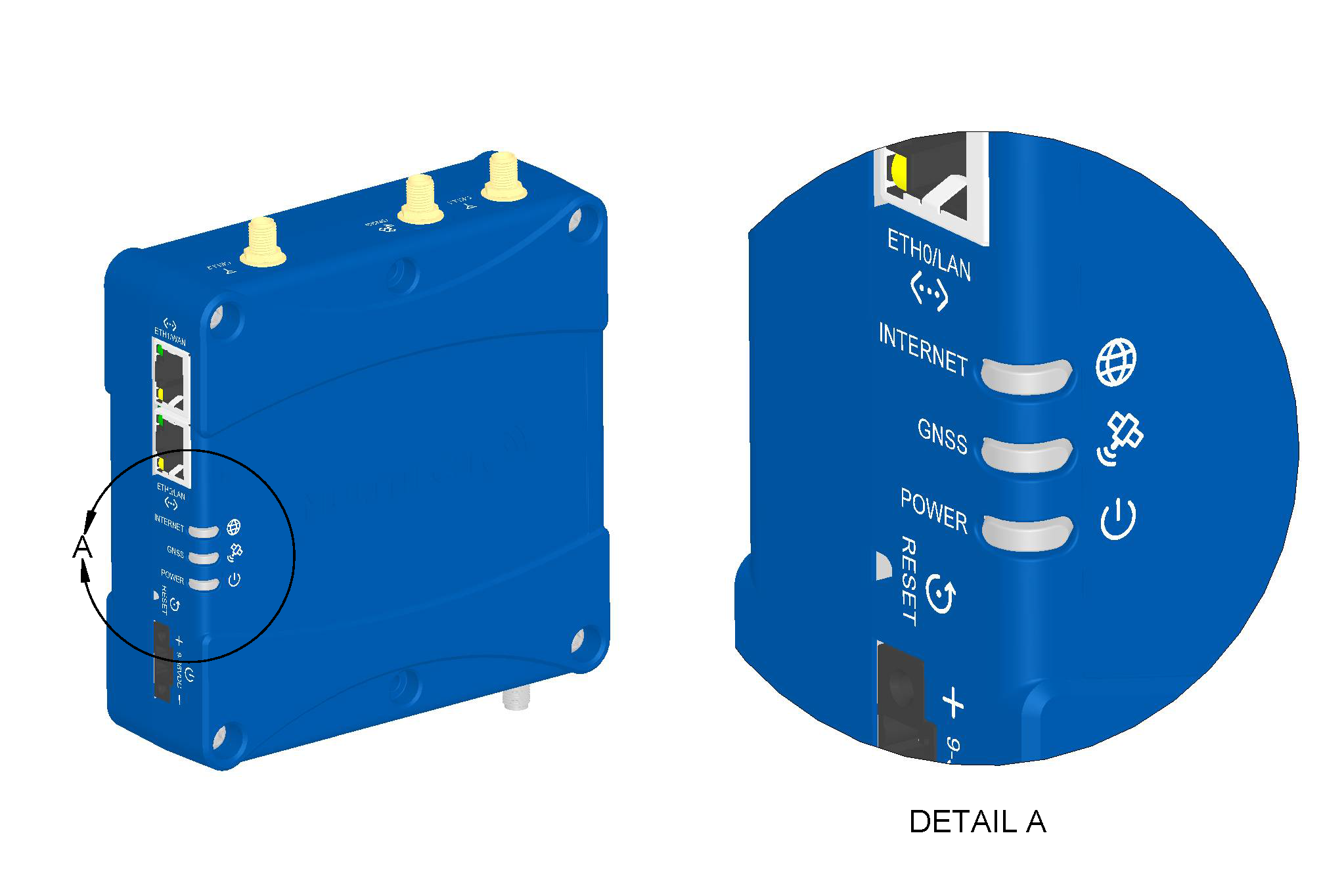
| LED | Description |
|---|---|
| INTERNET |
|
| GNSS |
|
| POWER |
|
Ethernet LEDs
The ETH0/LAN and ETH1/WAN connectors each have the same two LEDs.
| LED | Description |
|---|---|
| Ethernet link LED |
|
| Ethernet speed LED |
|
Serial and Digital IO Interfaces
The rCell 300 is a DCE serial device capable of supporting the RS‑232 and RS‑485 electrical signaling modes. The terminal block labeled RS‑232 supports a 7‑wire RS‑232 connection. The terminal block labeled RS‑232/RS‑485/DIO can be configured for RS‑485 half‑duplex or 4‑wire RS‑232 connection. This connector also supports a digital input and digital output signal. The digital IO function is not shared with the serial port pins.
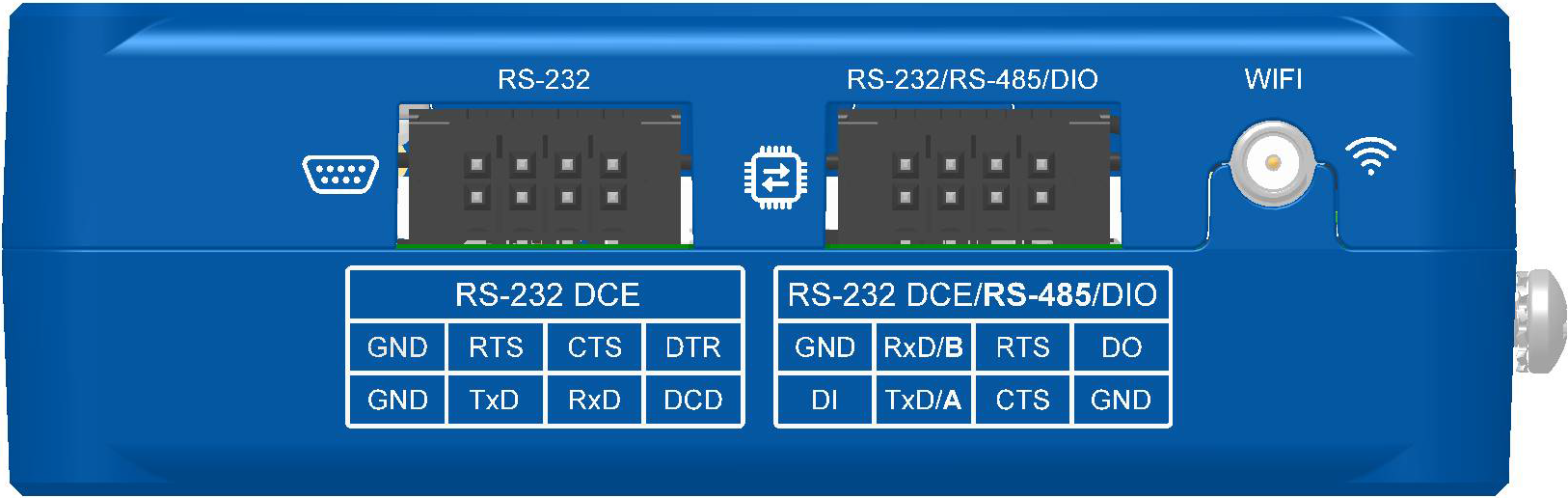
Terminal Block Connector Pinout
RS-232 Terminal Block Pinout
| Pin Number | Signal Name | Description | Signal Direction |
|---|---|---|---|
| 1 | GND | Main GND; connected internally to Digital GND | N/A |
| 2 | GND | Main GND; connected internally to Digital GND | N/A |
| 3 | TxD | Transmit data | Input |
| 4 | RTS | Ready to send | Input |
| 5 | RxD | Receive data | Output |
| 6 | CTS | Clear to send | Output |
| 7 | DCD | Data carrier detect | Output |
| 8 | DTR | Data terminal ready | Input |
RS-232/RS-485/DIO Terminal Block Pinout
| Pin Number | Signal Name | Description | Signal Direction |
|---|---|---|---|
| 1 | DI | Digital input | Input |
| 2 | GND | Main GND; connected internally to Digital GND | N/A |
| 3 | TxD (RS-232) | Transmit data | Input |
| RX+/TX+ (RS-485) | Data + | Bidirectional | |
| 4 | RxD (RS-232) | Receive data | Output |
| RX−/TX– (RS-485) | Data - | Bidirectional | |
| 5 | CTS | Clear to send | Output |
| 6 | RTS | Ready to send | Input |
| 7 | GND | Main GND; connected internally to Digital GND | N/A |
| 8 | DO | Digital output | Input |
Serial Port Electrical Specifications
RS-232 Electrical Specification (TIA/EIA-232 Compatible)
| Parameter | Recommended Operation |
|---|---|
| Input voltage level (with respect to GND) | ±15 V (nominal), ±25 V (absolute maximum)6 |
| Ouput voltage level (with respect to GND) | ±12 V (nominal), ±13.2 V (absolute maximum) |
| Cable length (maximum) | 15.54 m/50 ft (Baud rate of 19,200 bps) |
| Baud rate (maximum) | 921,600 bps |
| Flow control | Hardware (RTS/CTS) |
RS-485 Electrical Specification (TIA/EIA-485 Compatible)
| Parameter | Recommended Operation |
|---|---|
| Communication mode | Half-duplex (2-wire configuration) |
| Differential voltage level (with respect to GND) | −7 V to +12V (nominal), ±16 V (absolute maximum) |
| Cable length (maximum) | 305 m/1,000 ft (120 Ω termination enabled) |
| Baud rate (maximum) | 921,600 bps |
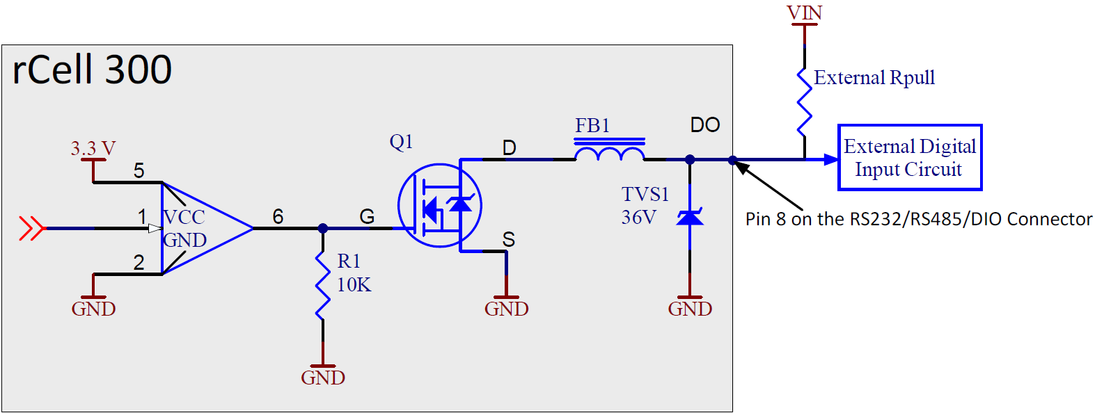
Digital IO Interface
Digital Input
Below is the digital input equivalent circuit connected to an external open-drain output.
As shown in this example, the external pull-up resistor (Rpull) value depends on the pull-up voltage VIN. Starting at VIN > 3.5 VDC, an external pull-up resistor must be added as shown above.

Digital Input Specification
| Logic State | VIN Minimum | VIN Maximum | Units |
|---|---|---|---|
| LOW | 0 | 0.8 | V |
| HIGH | 2.4 | 36 | V |
Digital Output
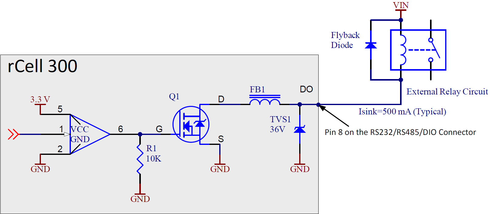
The digital output pin can be used in an open-drain configuration or as a low-side current-sink output; for example, to drive an external solenoid/relay circuit.
The digital output pin can typically sink 500 mA, but it can vary with operating environmental conditions such as temperature.
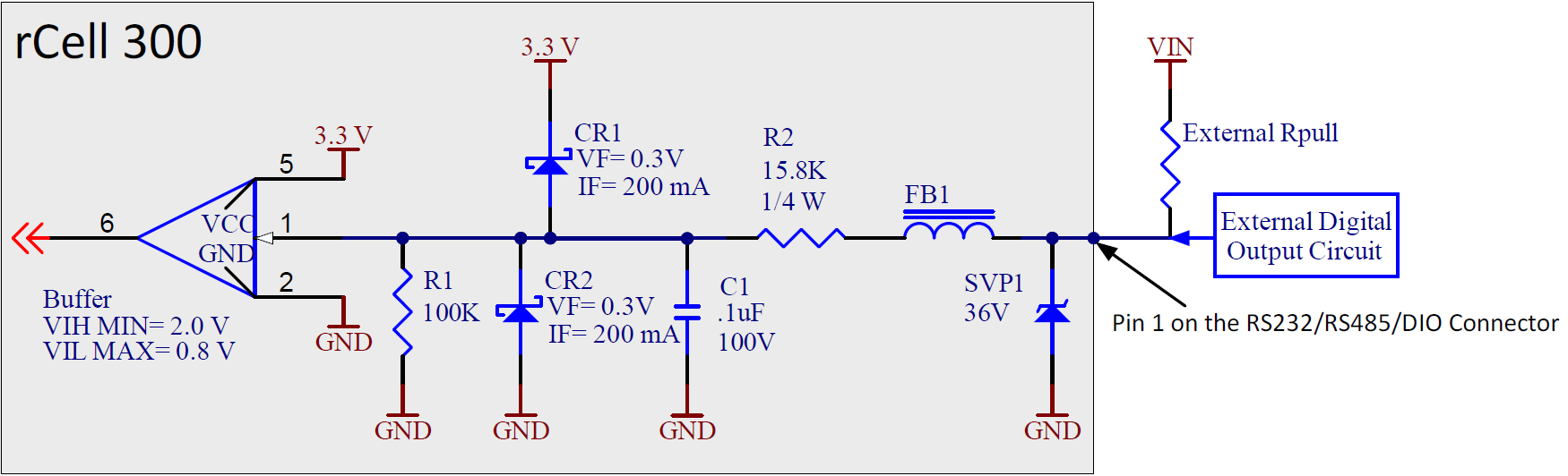
Open Drain Output
Below is the digital output equivalent circuit in an open-drain configuration driving an external digital input.
Low-side Current Sink
The digital output can be used as a low-side current sink to drive a relay or solenoid.
To prevent damage to the transistor, add a flyback diode across the relay coil.
Power Supply Requirements
The device should be used with a UL LPS-certified power source that has an output voltage between 9 VDC and 36 VDC and a minimum rating of 9 W. The actual power consumption depends on the selected input voltage. A 9 W power source is sufficient to cover the entire input voltage range. For safety information, see Customer‑Provided Power Supply and Power Cable.
Customer‑Provided Power Supply
A customer‑provided power supply must meet the following requirements:
- Listed ITE safety certified
- Rated for use at 5000 m
- Marked LPS
- 9–36 VDC; rated for the range, or within the range
- 9 W minimum (see Power Supply Requirements)
- Rated 40 °C or higher (safety agency certified operation temperature)
Customer‑Provided DC Power Cable
A customer-provided DC power cable must meet the following requirements:
- UL or other safety-recognized wire (AVLV2 or ZJCZ)
- VW‑1, FT1, FT2, SPT‑1 or better
- 36 V or better
- 18 AWG or better
- 80 °C or better
Sample Power Measurements
The measurements below are based on a specific configuration. Power consumption varies with operating environmental conditions such as temperature and strength of cellular and Wi-Fi signals.
MultiTech recommends incorporating a 10% buffer into your power source when determining product load.
| Radio Protocol | Live Connection or Callbox Idle (No Data) | Average Current, | TX Pulse Amplitude Current for Peak Current (Average)9 | Total Inrush Charge10 | Total Inrush Charge Duration During Power Up (Inrush Duration) |
|---|---|---|---|---|---|
| MTR3‑L4G2D‑AC00PA‑EWM | |||||
| 9 Volts | |||||
| GSM 850 MHz | 155 mA | 272 mA | 752 mA | 1.73 mC | 9 ms |
| WCDMA 1854 MHz | 181 mA | 550 mA | 656 mA | 1.73 mC | 9 ms |
| LTE Band 8 897.5 MHz | 173 mA | 491 mA | 596 mA | 1.73 mC | 9 ms |
| 32 Volts | |||||
| GSM 850 MHz | 96 mA | 125 mA | 200 mA | 5.09 mC | 31.8 ms |
| WCDMA 1854 MHz | 88 mA | 182 mA | 276 mA | 5.09 mC | 31.8 ms |
| LTE Band 8 897.5 MHz | 87 mA | 166 mA | 268 mA | 5.09 mC | 31.8 ms |
| MTR3-L4G2D-AC00QA-EWM | |||||
| 9 Volts | |||||
| GSM 850 MHz | 145 mA | 237 mA | 628 mA | 2.0 mC | 8.5 ms |
| WCDMA 1854 MHz | 142 mA | 464 mA | 560 mA | 2.0 mC | 8.5 ms |
| LTE Band 8 897.5 MHz | 147 mA | 452 mA | 544 mA | 2.0 mC | 8.5 ms |
| 32 Volts | |||||
| GSM 850 MHz | 84 mA | 109 mA | 176 mA | 6.3 mC | 38.7 ms |
| WCDMA 1854 MHz | 84 mA | 161 mA | 236 mA | 6.3 mC | 38.7 ms |
| LTE Band 8 897.5 MHz | 85 mA | 159 mA | 232 mA | 6.3 mC | 38.7 ms |
Cellular Radio
Radio-Conducted Transmit Power
Telit LE910Cx Module (L4G2D)
| Band | Max. Output Power | Power Class |
|---|---|---|
| 2G (GSM) LB | 2 W, 33 dBm | 4 |
| 0.5 W, 27 dBm EDGE | E2 | |
| 2G (GSM) HB | 1 W, 30 dBm | 1 |
| 0.4 W, 26 dBm EDGE | E2 | |
| 3G (WCDMA) | 0.25 W, 24 dBm | 3 |
| TD-SCDMA | 0.13 W, 21d Bm | 3 |
| 4G (FDD and TDD) | 0.2 W, 23 dBm 1 RB | 3 |
Antenna Information
Cellular Antenna
The cellular/wireless performance depends on the implementation and antenna design. The integration of the antenna system into the product is a critical part of the design process. Therefore, it is essential to consider it early so that the performance is not compromised. Devices were approved with the antenna(s) described below and for alternate antennas meeting the given specifications.
The antenna system is defined as the SMA connection point from the device to the specified cable specifications and specified antenna specifications.
Selecting Antennas
Select an antenna based on your product and application. Typically, both antennas are the same and either can be the main receive antenna. The required antenna impedance is 50 ohms. The antenna selected must meet the requirements for FCC/IC Compliance.
Requirements for FCC/IC Compliance
The rCell 300 is approved for operation with the antenna listed below and antennas with maximum gain including cable loss of the following:
- 8.51 dBi for Band 2 and Band 25
- 5.5 dBi for Band 4
- 6.91 dBi for Band 5 and Band 26
- 9.91 dBi for Band 8
- 9.7 dBi for Band 12
- 9.91 dBi for Band 13 and 14
- 9.01 dBi for Band 7
The following cellular antenna is approved for use with the rCell 300:
| Manufacturer | Wieson |
|---|---|
| Manufacturer Model Number | ARY118-0167-005-00 |
| Antenna Type | LTE dipole antenna |
For the MultiTech ordering part number, see Accessories.
Antenna Specifications
| Category | Description |
|---|---|
| Connector | SMA(M) |
| Operating frequency range | 0.617–0.96 GHz |
| 1.710–2.69 GHz | |
| 3.3–6 GHz | |
| VSWR | 3:1 maximum |
| Peak gain | 3.36 dBi (max) |
| Impedance | 50 Ω |
| Radiation | Omnidirectional |
| Polarization | Linear |
Placing External Antennas
The antenna placement strongly affects the device's overall performance. MultiTech recommends that each cellular dipole antenna be tilted 45° from vertical and away from each other. However, the optimal placement can vary with the specific requirements of the application and the operating environment.
Antenna Approvals and Safety Considerations
- Network operators conduct antenna diversity tests.
- There are no EMC concerns about antenna diversity.
- All antennas that contain plastics require a minimum flammability rating (UL94‑HB).
- Safety requirements depend on your final product.
- Unless otherwise noted, antennas are not approved for outdoor use. Do not extend any antenna outside of any building, dwelling, or campus.
Wi‑Fi Antenna
Requirements for FCC/IC Compliance
The following Wi-Fi antenna is approved for use with the rCell 300:
| Manufacturer | 2J Antennas USA |
|---|---|
| Manufacturer Model Number | 2JW1102-C943B |
| Antenna Type | 2.4 GHz/5.0 GHz dipole antenna |
For the MultiTech ordering part number, see Accessories.
For more information on FCC compliance, see Regulatory Information.
Antenna Specifications
| Category | Description |
|---|---|
| Frequency Range | 2.4/5.0/6.0 GHz |
| Impedance | 50 Ohms |
| VSWR | VSWR should not exceed 2.0:1 at any point across the bands of operation |
| Peak radiated gain | 4.1 dBi for 2.4 GHz |
| 3.9 dBi for 5.0 GHz | |
| Radiation | Omnidirectional |
| Polarization | Linear |
| Connector | RP‑SMA(M) |
GNSS Antenna
The GPS antenna is included in the MTR3-L4G2D-AC00PA-EWM and MTR3-L4G2D-AC00QA-EWM ordering options. GPS is just one part of the broader GNSS (Global Navigation Satellite System) spectrum. The provided antenna only covers the GPS spectrum. A multifrequency or multiconstellation antenna is required if you require coverage of the entire GNSS spectrum.
A dedicated regulated bias is provided to support active antenna GNSS application. The operating range of this power supply is output voltage of 3.0–3.1 V at 100 mA maximum.
The following GPS antenna is provided for use with the rCell 300:
| Manufacturer | Trimble |
|---|---|
| Manufacturer Model Number | 66800‑52 |
| Antenna Type | GPS Active Antenna with low-noise amplifier |
For the MultiTech ordering part number, see Accessories.
Antenna Specifications
| Category | Description |
|---|---|
| Connector | SMA(M) |
| Frequency range | 1,575.42 MHz ± 1.023 MHz |
| Impedance | 50 Ohms |
| VSWR | 2.0:1 max |
| Gain | 10–30 dBi |
| LNA current consumption | 40 mA max |
| Noise figure | < 2dB |
| Polarization | RHCP |
| Input voltage | 3.0 V ± 0.3 V |
Placing GNSS Antennas
GNSS antennas need a clear view of the sky. Position the GPS antenna so that nothing blocks its view of the sky.
Before Installation
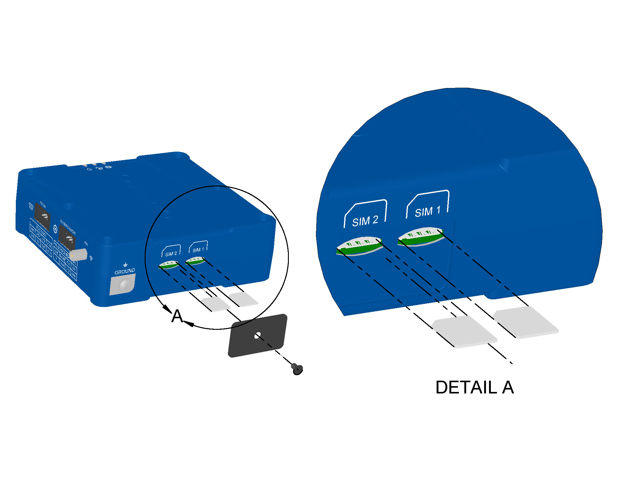
Install the SIM Card(s)
-
Using a #1 Phillips screwdriver, remove the SIM card cover.

- In the SIM 1 slot, insert the SIM card for the primary cellular network and push until it snaps into place.
- Optional: In the SIM 2 slot, insert the SIM card for the secondary cellular network and push until it snaps into place.
- Reinstall the SIM card cover.
Add the Device to Your Cloud Account
- QR Code
- Using a smartphone camera, scan the onboard QR code from the device serial label. See rCell 300 Serial Label.
- Follow the instructions to sign in to your cloud account and quickly onboard the device.
- Manually
- Sign in to your cloud account.
- Select Gateways.
- Under Actions, select Add device.
- Enter the PID number from the device serial label. See rCell 300 Serial Label.
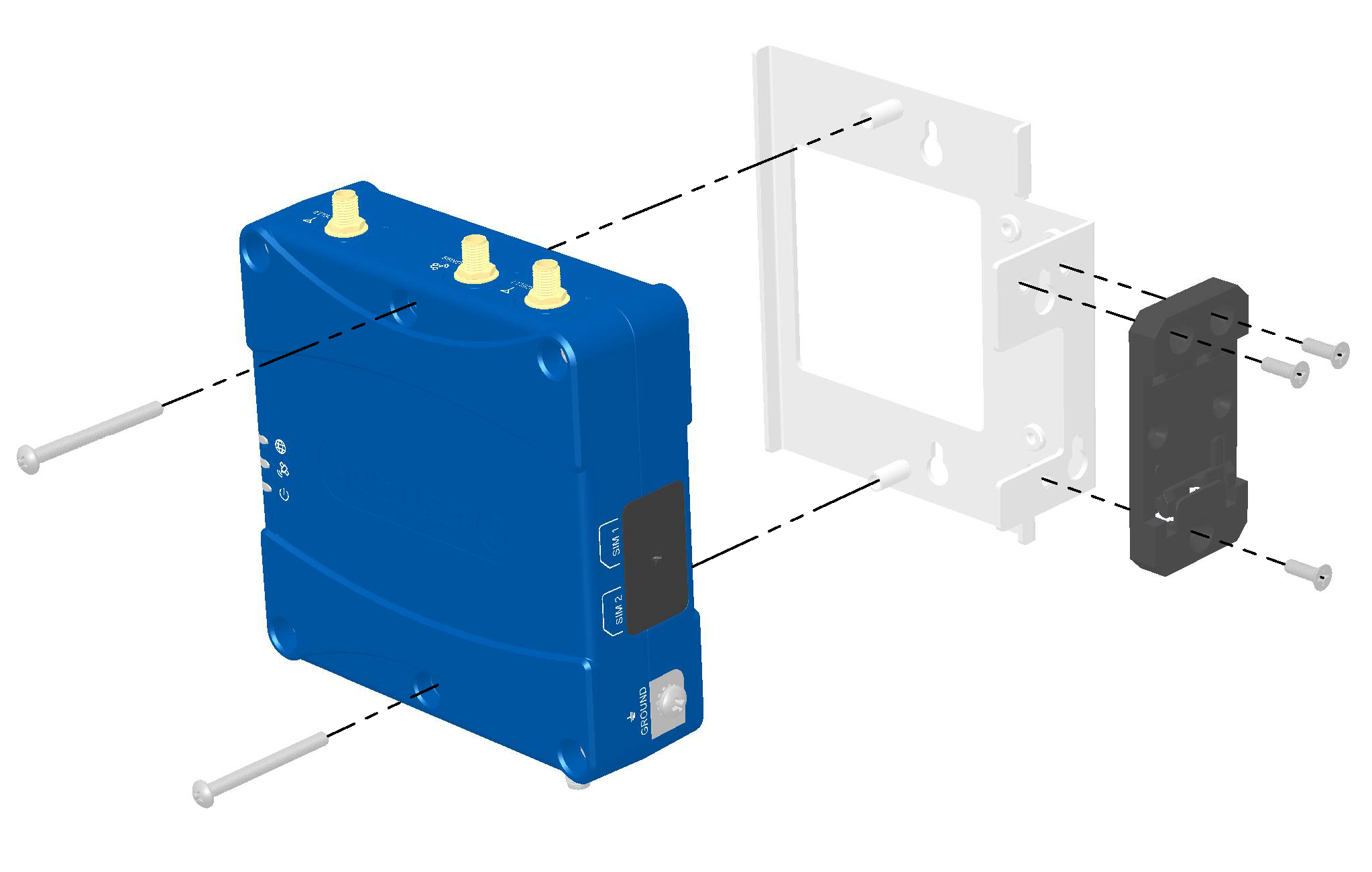
Mount the Device
- Wall-Mount Accessory
- Using the two keyholes on either side of the mounting bracket, secure the mounting bracket to the wall.
- Using the bolts provided and a #2 Phillips screwdriver, secure the device to the mounting bracket.
- DIN-Mount Accessory
- Using the bolts provided and a #2 Phillips screwdriver, secure the device to the mounting bracket.
- Using the three screws provided, attach the DIN rail clip to either the front or side of the device bracket as shown below.


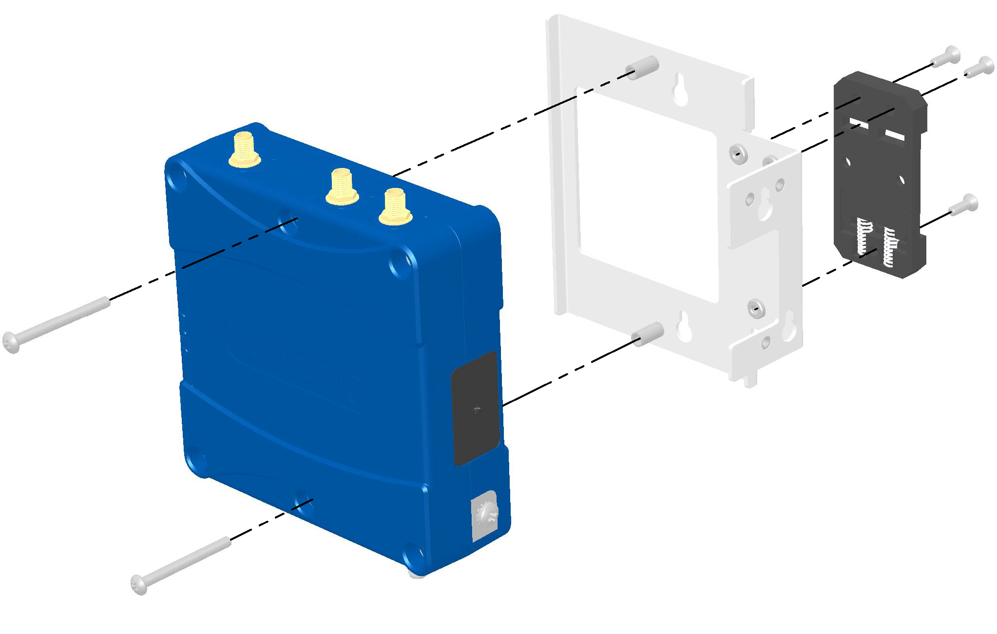
Mounting accessories are available separately. For details, go to www.multitech.com or contact your MultiTech sales representative. For MultiTech ordering part numbers, see Accessories.
Ground the Device
MultiTech recommends grounding the rCell 300 chassis to an earth ground.
- Using a #2 Phillips screwdriver, remove the ground screw.
- Attach the grounding lug of the grounding cable (cable not provided).
- Replace the ground screw to secure the grounding wire.
Installation
Install the Device
-
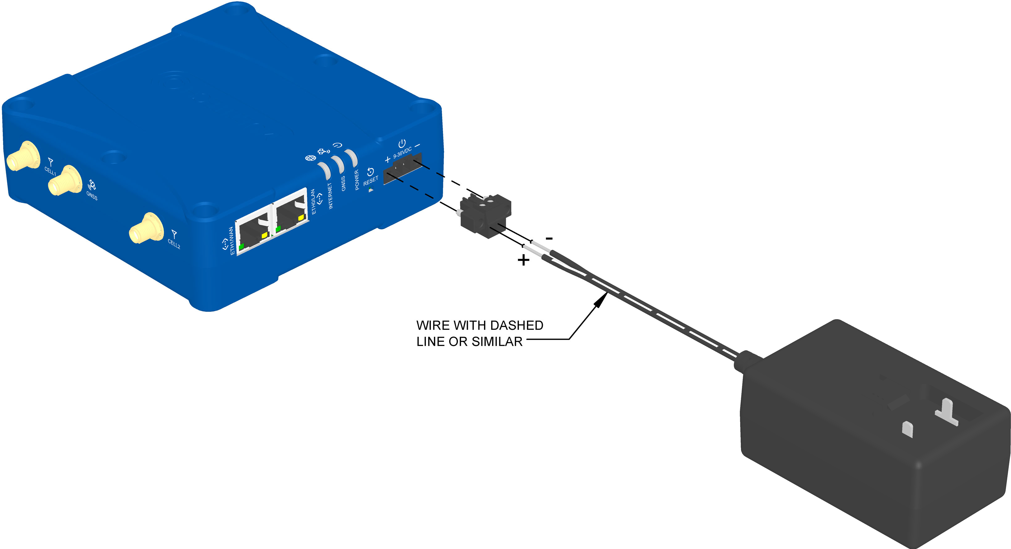
Connect the power supply:
- Using a 2.0 mm slotted screwdriver, screw the power supply wires into the 2-wire terminal plug.
- Secure the 2-wire terminal plug to the 9–36 VDC 2-pin terminal block on the device using a 2.5 mm slotted screwdriver.
- Connect the power supply to a power source. The POWER LED turns solid green when the device is ready for use.
The proper polarity is shown below.
Note: The customer should take steps to prevent any potential reverse polarity connections.
Operation
Reset the Device
To reset the device:
- Find the hole labeled RESET. The Reset button is recessed into the case.
-
Use the pin to press and release the Reset button as follows:
- To reboot, press Reset for less than 3 seconds.
- To reset to factory settings, press Reset for 10
seconds or longer.
- The device restarts in commissioning mode. The system automatically removes all user accounts.
- Enter a new username and password to create your new administrative account. See User Accounts in the appropriate software guide for details on username and password requirements.
Maintenance
Firmware Updates for Verizon
Verizon requires the cellular radio to have options for updating its firmware over the air. To comply with Verizon’s requirements, you must ensure that all Verizon lines or SIMs for devices are set up only via Verizon Thingspace. Thingspace has options for performing FOTA as needed. Additional radio FOTA support will be available in the future via a Cloud-based management system from MultiTech.
Troubleshooting
| Issue | Troubleshooting Steps |
|---|---|
| No LEDs or no communication |
|
| Cannot connect to the cellular network |
|
| Cannot connect to the Wi-Fi network |
|
| Intermittent cellular or Wi-Fi connection |
|
| Cannot access the rCell 300 web user interface |
|
If these troubleshooting steps fail to correct the problem, consider resetting the device to its factory default settings. See Reset the Device.
If you are unable to resolve the issue, contact MultiTech or your cellular provider for technical support.
Disposal
Instructions for Disposal of WEEE by Users in the European Union
The symbol shown below is on the product or on its packaging, which indicates that this product must not be disposed of with other waste. Instead, it is the user's responsibility to dispose of their waste equipment by handing it over to a designated collection point for the recycling of waste electrical and electronic equipment. The separate collection and recycling of your waste equipment at the time of disposal will help to conserve natural resources and ensure that it is recycled in a manner that protects human health and the environment. For more information about where you can drop off your waste equipment for recycling, contact your local city office, your household waste disposal service or where you purchased the product.
|
July, 2005 |
Regulatory Information
FCC Notices
FCC 47 CFR Part 15 Regulation Class B Devices
This equipment has been tested and found to comply with the limits for a Class B digital device, pursuant to part 15 of the FCC Rules. These limits are designed to provide reasonable protection against harmful interference in a residential installation. This equipment generates, uses, and can radiate radio frequency energy and, if not installed and used in accordance with the instructions, may cause harmful interference to radio communications. However, there is no guarantee that interference will not occur in a particular installation.
If this equipment does cause harmful interference to radio or television reception, which can be determined by turning the equipment off and on, the user is encouraged to try to correct the interference by one or more of the following measures:
- Reorient or relocate the receiving antenna.
- Increase the separation between the equipment and receiver.
- Connect the equipment into an outlet on a circuit different from that to which the receiver is connected.
- Consult the dealer or an experienced radio/TV technician for help.
FCC Interference Notice
- This device may not cause harmful interference, and
- This device must accept any interference received, including interference that may cause undesired operation.
FCC, EU, and Industry Canada RF Exposure Compliance
The antenna intended for use with this unit meets the requirements for mobile operating configurations and for fixed mounted operations, as defined in 2.1091 of the FCC rules for satisfying RF exposure compliance. This device also meets the European RF exposure requirements of EN 62311. If an alternate antenna is used, consult user documentation for required antenna specifications.
Compliance of the device with the FCC, EU, and IC rules regarding RF Exposure was established and is given with the maximum antenna gain as specified elsewhere in this document for a minimum distance of 20 cm between the devices radiating structures (the antenna) and the body of users. Qualification for distances closer than 20 cm (portable operation) would require recertification.
Wireless devices could generate radiation. Other nearby electronic devices, like microwave ovens, may also generate additional radiation to the user, causing a higher level of RF exposure.
Industry Canada Class B Notice
This Class B digital apparatus meets all requirements of the Canadian Interference‑Causing Equipment Regulations.
This device complies with Industry Canada license‑exempt RSS standard(s). The operation is permitted for the following two conditions:
- The device may not cause interference, and
- This device must accept any interference, including interference that may cause undesired operation of the device.
Cet appareil numérique de la classe B respecte toutes les exigences du Reglement Canadien sur le matériel brouilleur.
Le présent appareil est conforme aux CNR d'Industrie Canada applicables aux appareils radio exempts de licence. L'exploitation est autorisée aux deux conditions suivantes:
- L'appareil ne doit pas produire de brouillage, et
- L'appareil doit accepter tout brouillage radioélectrique subi, même si le brouillage est susceptible d’en compromettre le fonctionnement.
EU EMC, Safety, and Radio Equipment Directive (RED) Compliance
![]() The CE mark is affixed to this product to confirm compliance with the following European Community Directives:
The CE mark is affixed to this product to confirm compliance with the following European Community Directives:
- Council Directive 2011/65/EU on the restriction of the use of certain hazardous substances in electrical and electronic equipment; and
- Council Directive 2014/53/EU on radio equipment and telecommunications terminal equipment and the mutual recognition of their conformity.
MultiTech declares that this device is in compliance with the essential requirements and other relevant provisions of Directive 2014/53/EU. The declaration of conformity may be downloaded at https://multitech.com/product-support/.
Australia Regulatory Compliance Mark (RCM)
![]() This product complies with the requirements of the
Regulatory Compliance Mark (RCM) for Electrical Regulatory Authorities Council (ERAC),
Electrical Equipment Safety System (EESS), and the Australian Communications and Media
Authority (ACMA) for Electromagnetic Compatibility (EMC).
This product complies with the requirements of the
Regulatory Compliance Mark (RCM) for Electrical Regulatory Authorities Council (ERAC),
Electrical Equipment Safety System (EESS), and the Australian Communications and Media
Authority (ACMA) for Electromagnetic Compatibility (EMC).
Environmental Notices
EU WEEE Directive
The Waste from Electrical and Electronic Equipment (WEEE) Directive places an obligation on EU‑based manufacturers, distributors, retailers, and importers to take back electronics products at the end of their useful life. A sister directive, ROHS (Restriction of Hazardous Substances) complements the WEEE Directive by banning the presence of specific hazardous substances in the products at the design phase. The WEEE Directive covers all MultiTech products imported into the EU as of August 13, 2005. EU‑based manufacturers, distributors, retailers and importers are obliged to finance the costs of recovery from municipal collection points, reuse, and recycling of specified percentages per the WEEE requirements.
EU RoHS 3 Directive
Multi‑Tech Systems, Inc. confirms that all products comply with the chemical concentration limitations set forth in the Restriction of Hazardous Substances in Electrical and Electronic Equipment (RoHS 3) regulations for CE and UKCA, following the standard EN IEC 63000:2018.
For the current Certificate of Compliance for Hazardous Substances and additional regulatory documents, go to https://multitech.com/approvals-and-certifications/.
EU REACH‑SVHC Statement
Multi‑Tech Systems, Inc. confirms that none of its products or packaging contain any of the Substances of Very High Concern (SVHC) on the REACH Candidate List, in a concentration above the 0.1% by weight allowable limit.
For the current REACH‑SVHC statement and additional regulatory documents, go to https://multitech.com/approvals-and-certifications/.
Accessories
| Ordering Part Number | Description | Region |
|---|---|---|
| Power Supply | ||
| PS-12VCB-SWC-U-GLOBAL |
100−240 VAC/12 VDC power supply stripped wire connection; includes (4) power blades (Australia/New Zealand, Canada/United States, European Union, United Kingdom) |
Australia Canada European Union United Kingdom United States |
| PB-NAM-V2 LEVEL VI | Replacement power blade; US-style locking power blade, level VI |
Canada United States |
| PB-EU-V2 LEVEL VI | Replacement power blade; European-style locking power blade, level VI |
European Union |
| PB-GB-V2 LEVEL VI | Replacement power blade; GB-style locking power blade, level VI |
United Kingdom |
| PB-AU-V2 LEVEL VI | Replacement power blade; Australian-style locking power blade, level VI |
Australia New Zealand |
| Terminal Blocks | ||
| TBC-2-1 |
Terminal block connector, 2 wire
|
Australia Canada European Union United Kingdom United States |
| TBC-8-1 |
Terminal block connector, 8 wire
|
|
| Cellular Antenna | ||
| ANLTE7-2HRA |
|
Australia Canada European Union United Kingdom United States |
| ANLTE7-10HRA |
|
|
| ANLTE7-50HRA |
|
|
| Wi-Fi Antenna | ||
| ANWBT3-1HRA |
|
Australia Canada European Union United Kingdom United States |
| ANWBT3-10HRA |
|
|
| ANWBT3-50HRA |
|
|
| GPS Antenna | ||
| ANGPS-1MM |
|
Australia Canada European Union United Kingdom United States |
| ANGPS-10MM |
|
|
| ANGPS-50MM |
|
|
| Mounting Kits | ||
| DIN-MOUNT-1 |
DIN rail mounting kit
|
Australia Canada European Union United Kingdom United States |
| WALL-MOUNT-1 |
Wall mounting kit
|
|
Related Documents
Additional documentation is available at www.multitech.com.
| Document | Description | Part Number |
|---|---|---|
| API Developer Guide | Use the API interface to manage configurations, poll statistics, and issue commands. Go to www.multitech.net/developer/software/mtr-software/mtr-api-reference/. | N/A |
Revision History
| Revision Number | Description | Revision Date |
|---|---|---|
| 1.0 | Original publication. | February 2025 |
- MultiTech‑provided power supply: UL listed at 40 °C (limited by power supply)
- Customer‑provided DC power cable: UL listed at 75 °C (see Customer‑Provided DC Power Cable requirements)
- Customer‑provided power supply: Operating temperature determined by power supply specifications and environmental installation location (see Customer‑Provided Power Supply requirements)